Installing a radio in a car can be simple and quick, or it can be done correctly. With minimal skills in working with electricity, you can easily handle it yourself. But in every case there are nuances. Incorrect installation can result in distorted sound, failure to save settings, and in the worst case, fire. Find out how to properly connect a radio in a car in this article.
This is true; incorrect connections often lead to problems. So this is:
- Using a small gauge wire results in a drop in voltage and current when listening at high volumes. This means distortion of the sound, complete shutdown of the radio, overheating of the wire and fire.
- Long-term parking leads to incomplete or complete discharge of the car battery, making it impossible to start the engine.
- Turning off the ignition results in loss of settings.
To prevent this from happening, you need to do everything correctly, starting with the selection of wires, then deciding on the connection diagram and finishing with installation.
What wires to use to connect the car radio
To begin with, a typical diagram for connecting a radio with color pinout of wires is given. It is standard, but may vary in some colors for connecting speakers. This is to make it clear what the conversation is about.
Typical radio connection diagram
A diagram with the purpose of the wires and their color is shown on the top cover of almost every radio. It can be in both Russian and English. Where everything is more or less clear, but if it is given in English, then here are some explanations:
- FRONT - frontal (side).
- REAR - rear, rear.
- LEFT - left.
- RIGHT - right.
- +12 V, Battery, Memory, YELLOW - yellow power wire. It goes to the amplifier through a fuse; it is needed to power the memory, that is, to save settings. But it is advisable to install another fuse 30 centimeters from the battery to protect the wire and device;
- ACC, DC12V, RED - red. Controls switching on. On modern cars there is a key position in which all systems are de-energized except for some. The operation of a multimedia system is one of them.
- GND - black, body or minus of the car.
- GREEN - green.
- GRAY - grey.
- WHITE - white.
- BLUE - blue.
- BROWN - brown.
The first thing you need to do is stretch the wires, power, controls and audio systems. The wires must be reliable, with good insulation and with a selected cross-section.
The power supply of 12 - 13 volts is small, but the currents are solid. With a conventional audio system, it is assumed that there are a couple or two speakers, the current consumption will be up to 10 A. Most tape recorders have a 10 ampere fuse.
Which cable to connect the car radio to power
First. When choosing wires, look at the wire cross-section. The table below shows the correspondence between the conductor cross-section and fuse current, and for comparison, in the American measurement system (AWG).
Table for selecting wire cross-section based on fuse current
With a fuse current of 10 A, according to the table, 1 mm² is sufficient. Mathematically, everything is correct, but I assure you this is not enough. By stretching a wire with a cross-section of 2.5 mm² at full volume, you will see a decrease in the brightness of the radio backlight.
It's all about cable resistance. To connect a tape recorder from a battery you need at least 2 meters of wire. And even though copper has the smallest resistivity, it still has an effect. Take stranded copper wire with a cross section of 4 - 6 mm².
There are also silver wires, but they are very expensive. Don't even try Chinese aluminum ones.
The second important point is isolation. It should be thick and flexible at the same time. And it is better if it is a cable rather than a wire. Cables with the same cross-section have a stronger sheath. For flexible cables, the first position in the marking may be the letter “G”, which indicates that the cable is multi-core and flexible. For example, KG is a flexible cable. Has rubberized insulation.
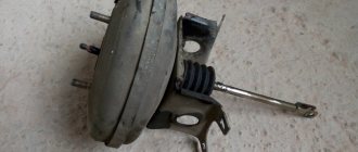
Example of a reliable connection to the battery output
To connect the car radio, it is more convenient to use multi-core wires. All connection points are in different places, so two or three wires are not needed.
Pinout of a standard Euro connector
A Euro connector is a standard plug used in most countries around the world. When connecting equipment, you may encounter non-standard wires tangled in a bundle. This problem is solved by purchasing adapters and pinouting the radio chips.
Standards 1din and 2din
Speaker system connectors come in two types: non-standard ones from the manufacturer, mostly pin-type, and standardized European ones, which are located at the back. Installation of equipment with a special audio connector from the manufacturer will require the use of a special proprietary connector. If the plug is ISO, then you can connect to it directly. There are two types of Euro connectors: 1din and 2din, the difference is in the height of the car radios. The two-block one is twice as tall; it is not connected to all cars, because there is no space on the panel for the required dimensions.
Radios with European 1din are the most common.
When installing car radios, wires with a small diameter of 1.5-2 mm are used, for power lines - with a large cross-section. Failure to follow these simple rules will distort the sound and damage the equipment.
| № 1 | — |
| № 2 | — |
| № 3 | — |
| № 4 | Constant power |
| № 5 | Antenna power |
| № 6 | Backlight |
| № 7 | Ignition |
| № 8 | Weight |
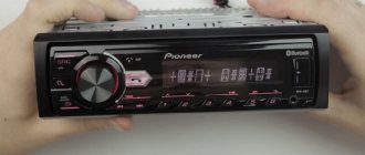
Manufacturers in Japan, the USA and some Chinese use the 2din standard.
Upper power connector A
The plug is used to supply electricity to the receiver, antenna and amplifier, as well as when it is necessary to control the backlight or turn off the sound signal. Standard color markings are used. Outputs 1-3 and 6 are not used in low- and mid-price segment speakers; they are intended for additional options for high-end products.
Connection types
- The first is the connection in the socket of wires of two colors, yellow and red, turning the receiver on/off does not depend on the ignition. The method is inconvenient because it predisposes the battery to discharge if the acoustics are not turned off;
- The second wire is connected through the ignition switch, the yellow wire is connected to the on-board computer.
Functional purpose of the receiver outputs
| ANT | The connector is used if the car has a retractable antenna |
| Remote | Multiple speakers can be connected |
| Illumination | Allows you to change the intensity of the device's glow |
| Mute | Adjusting the sound |
| A4 | Turn on/off |
Pinout of radio ISO connector
| A 4 | Color yellow | Battery + Power |
| A 5 | Color blue | Antenna. |
| A 6 | Color orange | Backlight |
| A 7 | Color red | Ignition, 12V. When disconnected, reset settings to factory settings. |
| A 8 | Color black | Acoustics |
Bottom speaker connector B
Used to connect amplifiers (2 cables each). The sound of the equipment depends on whether all connectors are connected correctly. The main thing is not to confuse them, otherwise the acoustics will be of poor quality.
Rules for connecting speakers by color marking of wires
| Color white | Left front |
| Color grey | Right front |
| Color green | Left rear |
| Color violet | Right rear |
Safety
Regardless of which car radio connection scheme you choose, you will have to pull at least one cable from the battery through the partition into the passenger compartment. A standard hole is sometimes provided for this purpose. In theory, the edges of this hole should be covered with a plastic or rubber bushing. Because even a non-sharp metal edge will wear out the insulation due to friction. We check the condition of the rubber or plastic and change it if necessary.
Standard hole edge protection
At the same time, inspect the other wires that are already lying here. Contact between exposed (damaged) wiring and the car body should not be allowed.
We stretch the wiring throughout the cabin so that the risk of damage is minimal. All areas where damage is possible (even theoretically) require additional protection. Use plastic or rubber pads, bushings, etc. Even 5–10 A is already serious.
Do not connect the negative speaker terminal to the car body. Modern amplifiers in a tape recorder have a different design. By attaching a speaker in this way to save on wires, you can damage the amplifier.
Possible problems and how to solve them
When using the radio, problems may occur due to connection errors. For example, the device will not turn on due to incorrect connection of the power circuits. If there is a fuse, it will blow if a short circuit occurs due to careless handling or connecting the power wires to the terminals of speakers or service devices.
To solve this problem, you should turn off the radio, remove it, inspect the wiring and check the connection according to the colors of the wires. The incorrectly connected wires are then disconnected and reconnected according to their intended purpose.
If after turning on the device there is no sound, then you should set the volume control to a position other than zero. If the radio suddenly turns off or an error message appears on the display, then there is a leak or short circuit in the speaker wiring. To deal with this problem, the integrity of the insulation and the location of the wires are checked. Damaged cables are replaced and moved away from hot and sharp objects.
Connecting a car radio if there is an ISQ connector
The general standardization of recent decades is not such a bad thing. If you have a relatively new car, it most likely has a block near the “seat” for the car radio for connecting it. It is made according to the ISQ standard and connected to the car’s electrical/audio system. In this case, connecting the car radio is the simplest - connect two connectors and everything should work. True, you need to know which connector on the car to install the adapter in, but this should be in the description of the car... Or you can try to understand it by the inscriptions next to the sockets.
The car radio should include an adapter for the ISQ Euro connector.
If the car radio does not have such an output, then it needs an adapter from the standard connector to ISO. More or less serious manufacturers make such a connector or there is an adapter included with the radio. If you don’t have it, you can buy it or you will have to look for it exactly for your brand/model of radio, which is problematic.
ISO connector
It is much easier to purchase an adapter and, guided by the colors and pattern given on the cover, hook up the radio.
Pinout of the ISQ Euro connector for connecting a car radio
You can, of course, connect the radio without a plug. It is enough to understand the terminals on it and connect (or stretch the wires to the speakers) without confusing the plus and minus of the speakers with the amplifier outputs. However, using a chip simplifies the connection when you need to replace the radio.
Why connect USB
Since the 70s of the last century, music has been heard from cars. At first, such a luxury as a radio in a car was not available to everyone. Only representative brands, for example Volga, could boast of it. The industry did not stand still, and soon the radio was equipped with a cassette recorder, and then began to support disks and even flash cards.
Motorists whose iron horse does not have a receiver that meets all modern requirements should not be upset. Installing USB into a standard radio is easy and does not require special skills. Almost anyone can cope with this task.
The input we are interested in allows you to listen to music from a flash drive (standard 2.0) connected to the audio equipment, if the car has a radio without USB and aux. It is convenient and in demand. Does not distract the driver from driving, unlike the situation when a telephone is connected to the radio.
Are you a car driver?! Then you can take this simple test and find out. Go to test »
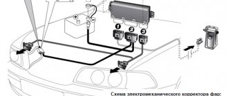
Radio connection diagrams
Not all models of domestic cars have a key position in the ignition switch in which it would be possible to turn off the power to the car's electrical equipment and remove the key. For example, position “0” for a VAZ 2107. In this position, when most consumers are turned off, the key is not pulled out.
A lock with an “ACC” position is only available on later models. Therefore, in order to protect yourself from battery discharge during prolonged inactivity, it is better to use one of the proposed schemes.
Connection to the ignition switch of imported cars
This method is “correct” for imported cars and “wrong” for domestic ones. The fact is that in imported cars there is a special key position in the ignition switch, signed ACC. When the key is in this position, power is supplied to the car radio, but the starter is not activated.
So, if you connect the car radio to the system of an imported car without an adapter, you need to:
- Connect the plus from the car battery (usually yellow) to the corresponding socket in the car radio.
- The second connection point is the ignition switch terminal labeled ACC and the same connector on the radio.
Diagram for connecting a car radio to the ignition switch of an imported car. The diagram is more than simple and understandable. The tape recorder will work either while the motor is running or if the key is in the ACC position. If the key is in the neutral position, nothing works, there is no loss of charge.
In any circuit, it is worth installing a fuse in the voltage supply circuit from the battery (yellow wire). Even if it is at the input of the radio. It's much easier to replace the fuse on the wire than to look for what's burned out in the radio.
What will happen if you connect it to a domestic car using this scheme? That is, stretch one wire from the battery, and take the second from the ignition switch. The radio will only work if the ignition is on. The engine was turned off -
To the battery via a button
Sitting in the car in silence, or listening to the radio with the ignition on is not the best choice. Therefore, when connecting the radio, they try to ensure that it works even when the engine is turned off. One way is through a button that turns on when the engine is off. When turned on, it supplies 12 V from the battery to the second input of the radio, thereby ensuring its operation. When the motor is running, the button should be off. Then the device operates according to the classical scheme.
How to connect a car radio so that it works without the ignition
The disadvantage of this method is that you will forget to disable the button. And this accelerates the “drawdown” of the battery. As an option, install a button backlight in the circuit. It will light up when the button is turned on, reminding you to turn on the power.
Self-retaining, correct operation scheme without ignition
This is one of the best ways to turn on a car radio in domestic cars. To start, you need to turn on the ignition. The device will start working and will work until you turn it off with the button. There will be power from the battery, but there will not be 12 V from the ignition switch and the device will go into sleep mode with minimal consumption. To turn it on again, you just need to turn on the ignition, and when the radio starts working, you can turn it off again.
Connecting a car radio with and without ignition
As you can see, for such a connection you will need two diodes with an operating voltage of more than 12 V and 300 mA. Turn them on towards each other - as in the diagram. Connect one end of this bundle to the output of the ignition switch. Connect the middle point (the junction of the two diodes) to the red wire. Connect the free end of the diode bundle to the antenna output (usually blue and white).
How does this scheme work? When the ignition switch is turned on, power flows through the diode and through the middle point is supplied to the +12 input. The ignition is turned off, and power is supplied through the second diode from the antenna terminal.
Connecting a car radio through an alarm system
There are two types of car alarms. The first is when -12 V appears when the alarm is disarmed, the second is when it is armed. The second option “without bells and whistles” will not work, since the radio will turn on when you arm the car. But with the first one - when the minus appears when the signaling is turned off - you can connect the car radio according to a simple circuit.
Connection diagram for car radio power supply via alarm system
If minus 12 V appears in the alarm after disarming, connect the terminal on which it appears to the relay coil. The second contact is powered by the battery. When the alarm is turned off, the relay is activated and supplies a positive signal to the tape recorder.
If a minus appears in the alarm when setting the alarm, then it is better to use a circuit with a button or implement another option.
Euro and ISO sockets and working with them
Experts call power connectors not chips, but sockets. This term comes from electronics and refers to the connection location. The pinout is also a way to connect an electronic device to the vehicle's on-board system. At the same time, the layout of the radio chip may differ for cars, for example, Toyota, Mitsubishi or Volvo, as well as for model brands - Sony, Pioneer, JVC and others.
EURO ISO car radio connector
Please note that adapters for the Euro connector are available for all car radios; this helps to avoid problems with pinout and allows you to unify and protect the “native” connections from damage when disconnected. It is these connectors that are usually called chips, although the term allows for a much broader interpretation. The Euro connector is also classified as an ISO connector.
Incorrect battery connection
There are a couple of possible connections that are popular but are incorrect. They are attracted by the simplicity and speed of execution. However, I would like to warn against using them.
Connect the red and yellow wires on the radio
In order not to make mistakes, you need to know what not to do. Often in domestic cars the car radio is connected only to the battery. Both input connectors are supplied with 12 volts from the battery. This is the easiest way to get the radio to work without the ignition, but it's not perfect.
Incorrect battery connection diagram
This method does not affect the performance of the radio. But, if you turn it off with a button, current will still be consumed. There is power as long as the car’s battery is alive and the device is always “in operation”.
The disadvantages are obvious - the battery drains faster if it is old. However, with a good battery, it will take weeks to discharge it to a minimum.
This method is good when you need to quickly check the performance of the radio. By applying a minus to the black wire and connecting the yellow and red wires to each other, when you press the power button it should turn on. You can check the sound by connecting any working speaker to the wires from the amplifier, for example, purple and purple with black.
From the cigarette lighter
Since the radio is located next to the cigarette lighter, there is a temptation to supply power from it. It’s easier, you don’t have to look for contacts and connectors. But you shouldn't do that. When using the cigarette lighter, the radio experiences interference.
The second disadvantage of this scheme is the “wrong” sound. If the speakers are powerful, you don't need to have a special ear for music to notice the difference. It really hits the ears.
What to do
If the head equipment does not save the settings when the ignition is turned off, then it is necessary to remove the product and check the switching circuit. At the same time, the presence of voltage is checked in the circuit to which the cable with a yellow protective layer is connected. On some vehicles, an on-board electrical system control unit is mounted, which de-energizes the circuits some time after the ignition is turned off. In this case, the wire is connected to the positive terminal of the battery, which allows you to remember the settings when the ignition is turned off.
On cars manufactured by VW and GM factories, original color markings of standard wiring elements are used. The yellow cable of the head unit is connected to the red cord, and the wire with the red insulating layer is connected to the yellow wire. A similar scheme is applicable when switching devices manufactured by Alpine. After changing the circuit, it is necessary to check the functionality of the equipment; turning off the contact group in the lock should not lead to resetting the programmed parameters.
Hyundai cars use a standard harness with an ISO standard block. To switch external equipment, an adapter is used with a metal jumper installed inside, connecting the positive cables into a common circuit that goes through the lock. In this case, after turning off the ignition, the car radio will reset the settings to factory settings.
Chevrolet does not use standard electrical wiring for multimedia equipment to separate the positive circuit into two paths. When replacing the standard radio, it is necessary to use adapters that provide power to the memory unit. It is allowed to use car radios equipped with a built-in autonomous power source (for example, a lithium-ion battery). The car owner can make a power supply with his own hands, but he should remember the need to charge the batteries and periodically replace the elements.