- The starter does not work on a VAZ 2115 - 6 answers
- Power drawdown up to 12.8V – 5 answers
- The radiator fan does not always turn on, VAZ 21099 injector – 5 answers
- There is a spiral hanging above the gas pedal in a VAZ 2114 - 5 answers
- What is the normal charging voltage for a VAZ 2115 battery - 4 answers
Weight of the ECM (electronic engine control system) - on the 1.5 engine on the engine body (on the plug mounts). On a 1.6 engine - on a welded stud.
The weight of the instrument panel is under the steering shaft mount.
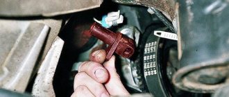
Battery weight - the negative on the battery has two wires . The thin one is attached to the body next to the battery itself. The thick one goes from the battery negative to the motor housing.
The mass of the electric motor is on the left side of the stove body, under the panel.
Good day everyone, Friends and just Guests! Maybe the topic is not new, but still, sooner or later we all face this problem. I kept thinking for a long time about the point of installing additional mass? Let me remind you a little how it all started and why it made me think about installing additional weight on the car body
Then I saw a post by viktor53rus
New additional mass that he installed additional mass
And then I thought about it a little, why not put additional weight on the body, start small, if this doesn’t help then we’ll look for the reason elsewhere
Almost 100%, you can even say 200% - on modern cars, the body is used as a single source of electricity. The car body is like a universal wire with a negative charge for all consumers of electricity. That is why the body is called the painfully familiar term “mass.” And why “painfully familiar”? Yes, because if somewhere the contact with the ground is either poorly secured or oxidized, after the first measurement I began to look for the reason, I started with the simplest where the weak “mass” places are on the VAZ 2114 2113 2115 with 1.5 liter engines. I’ll try to describe the places in which are most likely to result in the loss of a reliable connection to ground, and the glitches that appear in this case. This is the mass of the battery.
The “minus” on the battery has two branches: a thick wire and a thin one. A thick wire runs from the battery negative to the engine housing. If this contact is not secured properly, then the battery is not fully charged, the starter does not develop full power, and the ECM stalls (because it takes weight from the engine)
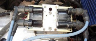
On the negative mount of the battery with the engine, you need to check the tightness of the two nuts between which the contact to the engine is attached: first of all, loosen the outer nut and tighten the inner one, and then tighten the outer one. The second wire from the battery is much thinner and is attached to the body next to the battery itself. This wire is the source for all energy consumers in the car. Here you also need to check the tightening torque of the nut both to the body and to the battery terminal. Look at this whole thing and if there is oxidation, then you need to clean it down to white metal and screw the whole thing back. Then we go to look further where the mass is attached. ECM mass in Samar 1.5 l engine, the mass for the ECM is taken from the engine housing, from the fastening of the plugs. The plugs are located on the right side of the block head
View from above
Number 1 is the ground where the ECM wires are attached, and Number 2 is where the engine ground is attached.
In practice, it happens that this pin No. 1 is painted at the factory and is loosely tightened. Therefore, over time it may become loose and at the moment the fan is turned on, there will be a drop in the voltage of the following sensors (which will lead to jumps in speed): DTOZH, TPS, MAF.
that absolutely all factory-made studs are not treated in any way other than paint, so over time corrosion, oxidation appears, and voltage drops begin. After all these inspection measurements, it was decided to put additional weight on the car body. A little history of how to do it And so I had a copper one in stock (why is it copper and not steel, since copper is the best conductor of current, because copper wires are installed on the starter and on the generator) wire with a cross-section I may be wrong, but I won’t say everything is in the photo
Then I measured my diameter with a caliper
to buy terminals. I bought terminals of the required diameter
They froze too
Then I stripped the wire
I put the terminals on and began to tighten them in a vice, since I don’t have a terminal press
Power supplies
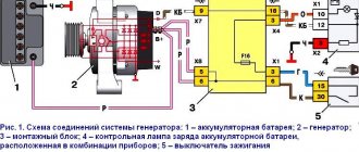
On the vast majority of modern cars, the power source is a three-phase alternating current synchronous generator driven by the main engine; three-phase alternating current from the generator is supplied to the built-in three-phase rectifier and voltage regulator circuit - in modern cars the voltage regulator is built into the generator housing. A car battery is used to provide constant and continuous power to some consumers when the engine is not running, such as lighting, car radio, brake lights, anti-theft alarm, as well as to fully power all vehicle systems when the engine is started. After starting the engine, the battery is recharged from the generator, and then it works in a buffer with the generator, smoothing out voltage drops when connecting powerful consumers. The generator power of a modern middle-class passenger car ranges from about 900-1300 watts.
Older cars used DC generators that were larger and heavier than three-phase generators; To maintain a constant voltage, a relay regulator was used, consisting of three devices - a voltage regulator, a current limiter and a reverse current relay.
In a number of cases, on special-purpose vehicles, as well as on armored vehicles, an additional generator driven by a separate internal combustion engine (the so-called auxiliary power unit) is installed, which makes it possible to supply consumers with electricity regardless of the operation of the main engine.
These include: switches and switches, relays, fuses, connector blocks, distribution and switching boxes, as well as power units.
What is the normal leakage current of a car battery?
Why is battery leakage current allowed, and why is the norm determined? What should be the leakage current of a VAZ car of old models and a modern AUDI? It depends on the equipment. Both cars have a clock, a security alarm, but the AUDI has an ECU that cannot be turned off, an audio system.
The clock consumes 1mA, the alarm system consumes 20 mA, the audio system consumes 3 mA - and the norm for current leakage in a VAZ car will be 24-30 mA. For AUDI, the norm will be 50-80 mA, but there the generator is more powerful and the battery is capacious. The standard current drain from the battery depends on its equipment.
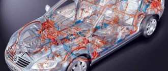
Electricity consumers
Vehicle systems, depending on model and configuration:
- ABS - anti-lock wheel system (anti-skid automatic braking)
- SRS - safety system (airbags, belt tensioners, etc.)
- EFI, ECM - electronic engine management systems
- Electronically controlled automatic transmission
- Trip computer
- and other
Lighting devices
Main article: Car lighting devices
Automotive lighting devices are divided into external and internal.
- External ones include headlights (with low and high beam), side lights, turn indicators (combined with hazard warning lights), brake lights, reversing lights, license plate lights, fog lights, contour lights, spotlights, and in some cases decorative lamps.
- Internal lamps include interior lighting lamps, engine compartment lamps, trunk lighting lamps, glove box lighting lamps, instrument panel lighting lamps, etc.
Other consumers
- Starter
- Ignition system
- On-board computer
- Electric power steering
- Fan motors, windshield wiper drives, power windows, etc.
- Heated glass
- Parking sensors (parking sensors)
- Reversing cameras
- Seat servos
- Cigarette lighter
- Radio (radio), TV, multimedia entertainment system
- Sound signal
- Anti-theft alarm
- GPS navigator, built-in or separate,
- Seat heaters,
- as well as other auxiliary and information systems and devices.
How to check a battery for current leakage with a multimeter
Taking the leakage current in your own car as the norm, you can measure the total parasitic currents with a multimeter. Exceeding the norm can occur due to a short circuit in the network or too powerful additional consumers. Sometimes the cause of current leakage from the battery is a malfunction of the generator or starter. Only through consistent testing of the network for current leakage can the true cause of the drain in the vehicle battery capacity be established.
How to measure battery leakage current
To diagnose current leakage, you will need a multimeter tester - it can work as a voltmeter, ohmmeter and ammeter with wires and alligator clips. You will need an open-end wrench, gloves and a notepad for notes.
The car should be prepared:
- turn off all electronics, including the DVR and amplifiers;
- disconnect hidden consumers in the glove compartment and under the hood;
- open the hood, secure it and loosen the negative terminal on the battery;
- close the doors, but open the windows so that you can enter the cabin if the central locking works.
All ground mounting points for the VAZ of the tenth family
| If the electrics in the car start to malfunction, then one of the reasons for this ailment may be poor fastening of the battery mass. Ten have features of mass fastenings depending on the engine and year of manufacture of the car. We check all the attachment points of the negative wire: |
Location of masses in the car interior
| 1 - fuse block.2 - near the driver’s right foot there is a shield, which is attached with a couple of screws, removing it, you will see that everything is like in the picture.3 - in principle, the situation is similar to the point described above, except that the shield is located next to with the left leg of the navigator. |
| The stud in the dashboard behind the mounting block, in order to find it, you need to bend in a certain way. The headlight hydraulic corrector is shown there for reference; the ground pin is located above and to the left of it. Through this mass, the windshield wipers, heater fan (21124) and door lock activators are powered. |
| The console is on the right side, from here it is more convenient to check the very important ground pin, through which the bracket under the ECU is connected to the car body, and accordingly the reliability of the ground of the ECM and the cooling fan depends - this nut also holds the corner that supports the far part of the left panel of the console. |
| ECM harness mass crimps in the console. The connector was removed from the ECU and pulled out onto the driver’s mat, it’s more convenient. I bit the fan ground wire out of the ignition circuit crimp (left in the photo), extended it, put the tip on and connected it separately to the bracket. I soldered all connections for reliability. |
| Weight of the Electric Fuel Pump (EFP) module and fuel level indicator. A black and white wire is attached to the left rear handbrake lever mounting bolt under the floor tunnel. The fuel pump is powered through this mass, and the accuracy of the fuel level reading also depends on it. |
| The ground is on the stud of the fuel pump flange; this wire most likely connects the pump housing to the fuel filter bracket and this was done for safety reasons to equalize the potentials of these two devices. |
It is easy to find the ground of the electric fuel pump module without removing the tunnel; just fold back the mat, slightly bend or carefully trim the carpet of the floor behind the driver's seat below the ashtray of the rear passengers, without damaging the ground wire itself. Then the carpet easily falls into place and the cut is almost invisible.
Location of masses under the hood of a car
The battery terminal is large and thick with a large cross-section wire (approximately 16 sq. mm). Its thick part, about the thickness of a little finger, connects the negative battery and the engine. If the contact of this wire is unreliable, there may be a deterioration in the battery charge, a decrease in the starter rotation speed when starting, as well as problems in the ECM system, because the minus comes from the engine, from the studs on which the ignition distributor hung on carburetor cars.
| The thin wire connecting the minus battery and the car body is the main connection for all electricity consumers in the car, and in carburetor modifications also for the engine. Through this connection, all the car's lighting equipment, radio and other devices are powered, depending on the year of manufacture of the car. |
| The connection point for the negative terminal of the battery to the engine block is connected to the upper stud of the thermostat, if you look behind the air filter. The cross-section of the wire was chosen based on the large current consumption of the starter; this wire can easily be traced by hand if it is led from the battery. The starter current flows through this wire, charging the battery, some sensors screwed into the engine block are connected through it |
| Nearby there is another ground connection point to the engine block, it is slightly higher and to the left. The 2112 engine has two brown wires connected to this place - this is the mass of the ECM, that is, the mass of the sensors, ignition module, ECU and cooling fan. The arrow below shows the engine (starter) ground wire from the battery. |
| The mass point under the adsorber - Miha [email protected] suggested that this is the mass of the right headlight and the mass of the right fog lamp. |
What is engine demining?
Structurally, the car has a developed electrical system, in which the serviceability and accuracy of the controllers, various sensors and many other electrical devices depend on the mass. The electrical ground (minus) is connected from the battery to the car body. The body is conventionally a return wire, forming a closed electrical circuit.
How to improve the mass of the VAZ ECM
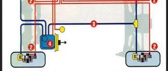
| If you notice that the engine speed fluctuates when the radiator fan is turned on, a possible reason is insufficiently reliable contact of the ECM ground with the vehicle ground. This is a known problem with the VAZ 2110 and VAZ 2113-2115 of the “new” model, in which the fan is controlled via a ground wire. We find out how to modify the weight of the car. |
Tests were carried out on a VAZ 21114, 2005 onwards, with a mileage of 7500 km, 8kl, 1.6l. Problem: When the car engine is warmed up, and the TPS position is 1-2%%, then at idle there is a noticeable (100-200 rpm) ) speed drift when the electric cooling fan turns on. At this moment, the voltage at the TPS output changes from 0.41 (when the fan is off) to 0.57 V (when the fan is on). Solution to the problem: Lay additional ground with a thick double-insulated wire (cross-section 2.5 sq. mm.) from the negative terminal of the battery to the metal frame of the center console of the instrument panel. The terminals at both ends of the additional wire are crimped and soldered. On a metal frame, our wire is secured to the stud for fastening the ground wires of the ECM, along with other ground wires. The terminals on the standard ground wire, which is installed between the battery negative and the car body, were also soldered. As a result: The voltage at the TPS output when the fan was turned on began to change within 0.39-0.46V. The result can be improved if the masses are separated ECM. After such modification, the readings will become 0.37-0.39V. Related measurements: The voltage on the green, ground wire of the TPS before and after reconnection practically does not change (it was 0.056-0.215V, now it is 0.03-0.03V). Also, as the contact of the ECM controller with the vehicle ground improves, a tendency for the voltage at the TPS output to decrease when the throttle valve is closed is noted. In the VAZ 2108-2115 family of the “old” type, the fan can be controlled by switching + 12V, so this modification option is not possible for them applies. By the way, if the electrics are faulty, then the cause may be poor ground contact.
Almost any car model is created according to the principle that its body is assigned the role of a single source of electricity. In other words, it is the base conductor with a negative charge to which all electrical appliances are connected. Thus, the weight of the Samara and other car models is attached to the body. Having understood this principle, it is much easier to calculate the causes of many problems associated with the car’s power supply. For example, quite often the Samara breaks down, which is reflected in the blinking of the headlights. However, a poor ground connection of the VAZ 2115 can cause much more serious damage, primarily related to engine operation and the electronic control system. This article will indicate the weakest points of VAZ cars in the context of working with “mass”.
Problems with bulk wires
The studs for fastening the common wires are often painted along with the body, and therefore the contact on them is not always reliable. In addition, they are fastened at the factory through a nut - first the nut is screwed onto the stud, then the minus is installed, and only then the wires are attracted to ground with another nut. The bottom nut is often poorly tightened, which is why electrical problems arise.
Often, mass-produced studs rust and the integrity of the contact is compromised.
To establish good contact with the common wire, you need to unscrew the top nut, remove the wiring from the stud, tighten the bottom nut all the way and put everything in place. It is a good idea to place a castle washer between the bottom nut and the body on the stud. The washer will have reliable contact with the body, and electrical problems will not arise due to poor mass.
How to find the location of a mass
Battery As a minus, a car battery has two conductors: one thin, the other thick. The role of the thick wire is to secure the ground in the VAZ 2114 from the battery negative to the motor housing. A faulty contact in this area leads to a decrease in charge transfer from the battery, a drop in starter power, and ECM problems.
To make sure that the ground is properly connected to the engine, you need to inspect the two fastening nuts that secure the contact to the engine body. To do this, slightly loosen the outer nut and tighten the inner nut, after which we apply additional tension to the outer one. The role of the thin wire is to connect the battery to the area of the car body in close proximity to the battery. This conductor is a single source for all electrical appliances in the car. The process of checking contact is also carried out by tightening the nut near the terminal and near the body. ECM Power for the control system is supplied from the engine housing, namely from the plugs located on the right side of the head block. Answering the question, where is the mass of the VAZ 2110 engine, which is equipped with a new generation ECM, the mass is taken from the stud attached to the dashboard frame. Sometimes it happens that the pin is not tightened too securely and eventually becomes loose.
Instrument panel The connection in this case is located in the area of the torpedo harness, combined with the mounting relay block and fuse system. It is located under the steering shaft mount. Malfunctions of this connection can lead to incorrect instrument readings during operation of large energy consumers, for example, headlights.
Heating motor The connected mass of the heating motor is located under the instrument panel, on the left side of the body. The main reason for the loss of conductivity properties by contacts is the fact that their surfaces are not treated in any way by the manufacturer, in addition to applying a layer of paint.
Troubleshooting
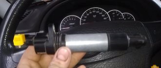
For uninterrupted operation of the battery, the system must be equipped with good quality wires; in this case, copper wires are the most suitable, since they have the best characteristics when operating under voltage.
The thin positive wire coming from the generator must be replaced with a thicker wire.
To protect the existing mass and ensure longer and more trouble-free operation, it is necessary to treat all existing connections and terminal contacts with a special lubricant that has an anti-oxidation function.
You can strengthen the mass by placing additional mass near the generator. Of course, you should not use a thin negative wire to connect to the car body; it is better to use a thick wire. The result will be better, and if problems arise with the main wire, the additional one will be able to start the car, and again you will not have to listen to the clicking of the relay.
As a result of the procedures performed, the car will start more confidently. We will eliminate the problem of frequent battery discharge, which will avoid the loss of much-needed volts for the car and, as a result, ensure the most stable and sufficiently high voltage coming from the generator.
The article was written thanks to the “Crafts” website. This is a creative portal that contains the best master classes on needlework, practical tips on the house, knitting, embroidery, decoupage.
Source
Normal car battery voltage. Under load and without it, let’s not forget about winter.
The voltage of a vehicle battery, as well as its capacity, are the most important indicators of this automotive unit, on which its functionality and quality of work directly depend. Batteries are used to start the power unit, so every car owner should know what the normal voltage of a car battery is, constantly maintaining it in working condition. Of course, I have already touched on this topic in previous articles about batteries , but today I want to clarify this information...
THE CONTENT OF THE ARTICLE
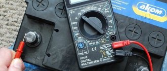
To begin with, I would like to say that modern cars no longer have devices that measure “Volts,” although they used to exist. Therefore, to determine the voltage, you first need to get a multimeter; read more about this here . I would like to note that it is advisable to check the battery voltage at least once a month or two in order to take timely measures.
Poor ground on the instrument panel, electrical grounding points (torpedo harnesses)
For the 2108-9 and 2113-15 families, the only connection point between the torpedo harness, the rear harness and the mounting relay and fuse box circuit is on the power steering shaft mount, under the instrument cluster. If the contact in this connection is unreliable, deviations of the arrows of the temperature and fuel level indicators are possible when the side lights, direction indicators, sound signal, windshield washer, windshield wiper and other consumers are turned on. For the lazy 'diagnostician type' in the 2113-15 family, it is possible to throw the 'snot' from the mass of the cigarette lighter onto a metal structure inside the center console of the instrument panel - a 'beard', with a wire with a cross-section no smaller than that going to the cigarette lighter. But this is only if the factory instrument panel is installed. This can be determined by the presence of a fastening of the specified metal structure to the floor tunnel, the 'proprietary' fastening of the ECM controller - using a plastic adapter between the controller and the metal structure and a fixed diagnostic connector in the standard place behind the decorative plug under the ashtray. For conscientious diagnosticians: be sure to securely tighten the standard bolt after removing the instrument cluster. The same family has another ground connection, the heater electric motor. It is located under the instrument panel, on the left side of the heater housing.
For the 2110-12 1.5L and 21114, 21124 1.6L families, everything is different. There are more such connections there. The first ground connection of the vehicle is located inside the instrument panel, on the top left of the relay and fuse mounting block, under the sound insulation. On cars of the first years of production, the ground wires to the welded stud were approached on top of the sound insulation, and then someone’s bright mind came up with the idea of hiding the wires under it. So access to the stud is very inconvenient and is only possible using a tube wrench or an extended 10-mm socket. If there is insufficient connection in this place, when you turn on the headlights or electric window motors, the windshield wiper and washer may turn on, and the central door locking system may work.
The second connection is located on a welded stud, on the center console of the instrument panel, on the left side, above the left console screen, under the M6 nut. But even if this nut is tightened properly, and the problem remains, then we move on to the most important point of mass for the entire instrument panel, grounding the entire metal frame of the panel. This is a welded stud with M6 thread. It is located on the lower, inner (cabin) side of the engine shield, in the middle. The nut screwed onto this stud also secures the bracket that secures the front part of the left screen of the console, which some diagnosticians and electricians mercilessly remove due to the fact that there are frequent cases of damage to the ECM harness or central locking system on this bracket. As a rule, the nut is tightened very, very mediocre. If there is insufficient contact in this and the previous connection, when turning on the side lights, headlights and radiator fan motor, deviations of the temperature and fuel level indicator arrows are possible.
In the NIVA family with all types of controllers, the mass of the torpedo harness is attached with a nut to the welded pin for fastening the relay bracket, and, as has become customary, it is tightened very loosely. This pin is located behind the standard fuse block. The mass of the engine compartment harness is attached to one of the welded studs securing the brake fluid reservoir. The mass from both radiator cooling fans is also screwed there.
In a Chevy Niva car, the main connection point of the harnesses to ground is in the upper left part of the engine shield on the passenger compartment side, also on a welded stud. To access the connection, you need to unscrew the decorative cover covering the mounting relay and fuse block and this block itself. Another problem area of the Chevy Niva is the power mass of the battery, which is screwed to the body next to the chain tensioner.
There are also 2 ground wires on the ECU mounting bracket. In the photo, the ECU has been removed for clarity.
In the VAZ 2104 - 07 “classic” family, the mass of the torpedo harness is attached to a welded pin behind the instrument cluster, along with the turn relay.
I would also like to note this important detail: absolutely all the studs to which the ground wire terminals are attached are painted at the factory along with the body; they do not have any protective coating other than a layer of paint and are therefore susceptible to corrosion when the paint is removed and there is no additional protective lubricant.
To ensure proper contact of these terminals with the body, the factory uses castle washers, which, unlike Grover washers, should not be between the terminal and the nut, but between the body and the terminal. With its sharp edges between the cut-out teeth, the washer with one side facing the body pierces the paintwork, and the other side facing the terminal firmly digs into it. The correct location of these washers should be the first thing to pay attention to when clients contact us about faults in electrical equipment after performing reinforcement work carried out during the process of tin-painting or other repairs. In particular, when removing the bracket for fastening the air intake hose on the tenth family, which sits on the stud fastening the negative battery wire to the body, the specified washer must be located between the body and the bracket.
In conclusion. If you have found a place with poor mass contact, take the time to separate all connections from each other, identify burnt or oxidized areas, and thoroughly clean and level all contacting surfaces before final assembly. Above is a small gallery of connecting mass power points on domestic car engines.
Electrical ground diagnostics
The following sections are divided between tests. This will make it easier to test the starter and accessory ground paths to identify common electrical system problems.
Here are some important points to keep in mind when troubleshooting your car:
You can use the remote starter switch to crank the engine while testing your vehicle. Connect the switch to the battery and the "s" terminal on the starter solenoid or remote starter relay.