A voltage regulator is an electronic device installed on car alternators to stabilize the input voltage to the battery. It should be between 13.2 - 14.5 volts. Deviations both upward and downward are unacceptable. This will already be a malfunction of the generator. In most cases, the voltage regulator is the culprit of the malfunction. Although this device is small in size, it protects the battery from premature failure.
Types and types of relay regulators
Depending on the type of relay, the method for determining performance also depends. Regulators are classified into 2 types:
Combined relays - this means that the relay itself with the brush assembly is located in the generator housing.
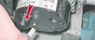
Separate relays - this means that the relay is located outside the generator housing and is mounted on the car body. You've probably seen a small black device attached to the fender of the car, wires go to it from the generator, and from it to the battery.
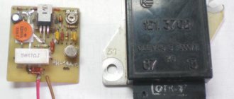
A distinctive feature of regulators from other devices is that the relays consist of a non-separable housing. During assembly, the body is glued with sealant or special resin. There is no point in disassembling and repairing it, since such electrical appliances are inexpensive.
What else could it be?
Often, the culprit for charging problems may not be the regulator itself, but its terminals; over time, like many on a car, they oxidize - which prevents the generator from working normally and recharging our battery, so first, before changing this unit, try to clean it, remove oxides and other deposits. By the way, this also applies to the battery terminals; they need to be cleaned and protected at least once a season.
Therefore, first of all, if the multimeter gives you 11 or slightly below 12V at the terminals of the machine, try cleaning the terminals and contacts first, then measure again. It is quite possible that this is the reason.
This is where I end the article, I think it was useful, read our AUTOBLOG.
Similar news
- Is there an automatic clutch? Let's look at the technical details...
- DIY brake caliper repair. Plus detailed video
- Spark plug gap. What should it be and what does it affect?
Add a comment Cancel reply
How to check the generator voltage regulator
A modern regulator, combined with a brush assembly, is used on most foreign and domestic cars. First, let's evaluate access to the generator. If it is difficult to access and inconvenient, then it would be better to remove it from the car. If access is free, then remove the relay from it without removing the generator. But before this, you must remove the negative terminal from the battery.
The regulator is attached to the generator from the rear cover side, usually with two bolts. We unscrew them and carefully, so as not to damage the brushes, remove it, having first disconnected the wires from it.
For further testing, we will need either a power supply or a charger, a 12-volt calvania lamp. The main thing is that you can increase and decrease the voltage from 10 to 16 volts. If you use a charger for testing, you will also need a battery. The fact is that many chargers do not work without it.
We connect the charger to the battery in normal mode. Additionally, we connect a multimeter and two wires to the battery terminals. One is positive, the other is negative. And we connect them to the relay regulator. The positive terminal of the regulator is a plug. The downside is a metal plate under one of the mounting holes. We connect the light bulb to the brushes with wires. The stand is ready, you can start testing. The power supply is connected in the same way, only without the battery.
We connect the charger to an external network and turn it on. The load regulator knob should be at the minimum level. We begin to slowly increase the tension. At the same time, the intensity of the light bulb should gradually increase. With a load of 12 volts or more, it should burn at full heat. We continue to gradually increase the voltage until the light goes out or the load reaches 15 volts. If the regulator is working properly, the light should go out at a voltage value of 14.2 -14.5. When the load decreases, the light will light up again.
If the light bulb goes out to 14 volts, or a voltage of more than 14.8 volts is reached, and the light bulb is still on, then such a regulator must be changed.
Checking a separate generator voltage regulator
A free-standing stabilizer is checked in the same way. Basically it is mounted on the body in the engine compartment. But sometimes on the generator cover. In any case, unscrew it and connect it to the stand. Let, for example, it be a Y112 V type stabilizer.
We connect the positive wire to terminals “B” and “C”, and feed the negative wire to the housing. We connect the control lamp to terminals “B” and “W”. Next, we do everything exactly the same as with the combined stabilizer. We gradually raise the load; when it reaches 14.5 volts, a cutoff should occur. If there is no cutoff, then change the regulator.
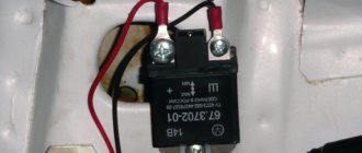
Checking the outdated 591.3702−01
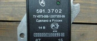
This obsolete type of relay was installed on almost all rear wheel drive vehicles. It is classified as free-standing. Always attached to the body of the engine compartment. The connection diagram for testing is slightly different from that described above. The actions and essence of the check remain the same.
There are only two contacts here. The markings are made with the numbers “67” and “15”. Contact numbered “67” is the negative terminal. Accordingly, “15” is a plus. We fix the negative wire from the charger to the device body. We attach the positive one to terminal 15. We connect the wires of the control light: one on the body, the second to terminal “67”. Our stand is ready for testing.
How to check the k1216en1 regulator with a multimeter
And finally, a few words about the k1216en1 relay. This regulator was installed on rear-wheel drive and front-wheel drive VAZs with injection engines. If we take into account the fact that there are many such cars in use throughout the post-Soviet space, we cannot ignore it.
This regulator belongs to a combined relay with a brush assembly. Its preliminary and main verification is carried out according to the method described above. There are no special differences.
Checking the functionality of the regulator
When diagnosing the generator voltage regulator, it is necessary to determine what breakdowns may be revealed during inspection (in order to avoid further malfunctions and effectively carry out preventive procedures).
Malfunctions while driving the car
- The light on the panel and other light sensors do not light up.
- The battery is low/overcharged and the regulator button is dark/bright.
The breakdowns can be as simple as a loose belt, a burnt-out relay, or worn out brushes.
To check the device you will need the following tools:
- sets of keys and screwdrivers;
- various testers;
- lamp 12 Volt 3 Watt;
- wires for connection;
- regulating current sources.
Checking the voltage regulator of the VAZ 2114 generator is carried out together with brush holders in order to immediately check the entire mechanism. You should carefully examine the condition of the brushes, their fragility, mobility, and length.
Check without removal. Using a voltmeter, we measure voltage readings. The optimal result is 13.5 - 14.2 V. If the data does not correspond to the norm, then there is a high probability of mechanism failure.
Before checking the voltage regulator and removing it from the car, you need to make sure that the fault lies in it and not in other components of the generator. How can I check this?
The first test option is diagnostics with the engine running using a voltmeter
What should be done? Start the engine and check the indicator light; if it does not go out and flashes brightly, it means there are problems in the generator. After a few minutes, when the engine increases speed and creates maximum conditions for the network load, we connect the meter and set 3500 rpm. Less than 13 Volts - the battery is completely discharged, when more - the regulator on the car needs to be replaced.
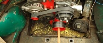
When you hear unusual noise from the unit, it means the bearings have failed, resulting in the drive belt being too tight. To adjust it, you need to turn off the ignition and release it. The deflection when pressed should not be less than two centimeters.
The second option is to check the mechanism on a stand
Before placing the electrical unit on the stand, you need to visually assess the condition of the brushes and slip rings of the commutator. Rings must be clean and dry. At the output, the current indicator gives at least 13 Volts, and the rotor speed is 6000 min-1. After 10 minutes of generator operation, the power output force can be measured. For a working unit, the indicators vary within 80 A.
Voltage regulator VAZ 2107 - purpose and first signs of malfunction
The voltage regulator is designed to automatically maintain the current strength so that the voltage generated by the generator is within specified limits, regardless of the rotation speed of the generator shaft (from the engine speed) and the current consumption of the car's electrical network. In VAZ 2107 cars, as a rule, an electronic voltage regulator is installed on the generator.
It is extremely rare that some models may come across an old-style device - a relay regulator. They were installed on generators 37.3701, produced before 1996, and on G-222. First, the device is tested on a running car. To do this, you need a voltmeter with the ability to measure DC voltage. The device must be equipped with a scale for values up to 15–30 V and have an accuracy class of at least 1.0. After starting the VAZ 2107 engine, it is allowed to run with the headlights on for 15 minutes at medium speed.
Then the voltage at the generator output is measured. To do this, the positive probe of the device touches terminal “30” on the generator, and the negative probe touches the ground (generator or car - it doesn’t matter, it’s the same thing). The voltmeter should show a voltage in the range of 13.6–14.6 V. If the measurement result is higher or lower than specified, and the vehicle is experiencing systematic overcharging or undercharging of the battery, then most likely the regulator is faulty and needs to be replaced.
Video
Useful video for auto electricians.
How the generator and voltage relay work.
If you find problems with charging the battery from the generator, you need to check the regulator relay. This device is directly responsible for the normal operation and efficiency of battery charging. Moreover, the overall service life of the battery will depend on the health of the regulator relay.
The job of the regulator relay is to accurately maintain the voltage produced by the vehicle's alternator. In other words, the relay regulator functions as a voltage stabilizer. The device keeps the voltage within strictly specified limits, limiting the possible decrease or increase in the value. This regulation occurs constantly and does not depend in any way on the speed of the crankshaft and generator, as well as on the degree of load created by various consumers in the on-board network. It turns out that the relay regulator controls the “plus” of the battery, supplying or stopping the supply of electricity depending on the voltage reading at the battery terminal.
Read in this article
Recommendations for increasing the service life of the regulator
In order to increase the service life of the voltage regulator, it is necessary to adhere to several simple rules aimed at implementing preventive measures. Among them:
- do not allow excessive contamination of the generator, periodically inspect its condition, and, if necessary, dismantle and clean the unit;
- check the tension of the alternator belt, tighten it if necessary (either yourself or in a car service);
- monitor the condition of the generator windings, in particular, do not allow them to darken;
- check the contact on the control wire of the relay-regulator, both its quality and the presence of oxidation on it;
- Perform periodic voltage checks on the vehicle battery with the engine running.
Following these simple rules will allow you to increase the resource and service life of both the generator and the vehicle voltage regulator.
Results
Checking the voltage regulator relay is not a difficult task, and almost any car enthusiast with basic repair skills can handle it. The main thing is to have the appropriate tools for this - a multimeter, a power supply with a voltage regulator (although you can connect it to a battery with a charger), a 12 V lamp and pieces of wires for mounting the appropriate circuit.
If during the inspection you find out that the regulator is out of order, then it must be replaced (repair work is usually not carried out). The main thing is not to make a mistake when choosing it and purchase the part that is suitable specifically for your car.
Problems of “undercharging”, as well as “overcharging” of the battery in principle, can be caused by many reasons, but the very first and most common on many cars (our VAZs are no exception here), as well as on many motorcycles, is the output of the generator relay-regulator from building. This device, despite its compactness, will protect your battery and make its service life much longer. However, if they fail, it can simply kill the battery in a matter of weeks, so if you see white streaks, and also, the engine does not start after night, even the starter does not “turn” - it’s time to check the relay regulator of your car, and here’s how it works do it yourself, and today I’ll tell you in detail...
To begin with, the definition
A relay regulator is a device that regulates the current from the car's generator, preventing the battery from overcharging, protecting it from overcharging, which is detrimental to the battery. Thus, this device greatly extends the battery life.
Essentially, this is just a voltage stabilizer that prevents the voltage from the generator from exceeding the threshold of 14.5 Volts; it is a very accurate device and is required for all types of cars. However, it can be distinguished into two types.
Tips and tricks
A common culprit for malfunctioning regulator relays may be oxidation of its terminals. This oxidation results in significant voltage loss. In this case, it is necessary to thoroughly clean the contacts and recheck. The voltage reading at the contacts should be similar to those given by the battery itself, that is, there should be no noticeable losses. Reduced voltage at the contacts indicates that they should be cleaned, and the regulator itself is often in working order. After cleaning, the terminals can be additionally treated with special chemicals that prevent further oxidation.
Finally, I would like to add that the cost of the regulator relay is not high. One of the surest ways would be to replace it with a new element if malfunctions are detected in its operation. Moreover, integrated relay regulators are a part in a monolithic housing that cannot be disassembled for repairs. Savings on this device are not justified, since rapid battery failure or a significant reduction in battery life will entail more serious costs when it is necessary to replace the battery.
Correctly charging a car battery with a charger. Before charging, check what current to charge the battery with. How to charge a battery without a charger.
The principle of operation and design of a car generator. The components of an alternator in a car: rotor, stator, windings, regulator.
How is the density of electrolyte in a battery measured, what does this indicator depend on. Affordable ways to increase the density in battery “banks” with your own hands.
For what reasons does the electrolyte in the battery become cloudy, gray or black? In what cases and in what ways can you restore battery functionality?
Why the starter may not work after turning the key in the ignition. The main causes of starter malfunctions: bendix, traction relay, brushes, winding.
Purpose, design features, installation location of the fuel pressure regulator of an injection engine. Signs of RTD malfunctions, checking the device.
A relay regulator is installed on cars to maintain stable voltage from the generator. This element protects the battery from overcharging, extending the battery life. It is the breakdown of the generator voltage regulator relay that is one of the most common malfunctions of the vehicle’s on-board network.
Unsustainable breakdown - hurry up with repairs!
It would seem that there is something wrong here - there is not enough tension. The car runs on gasoline, not electricity. However, a lack of current power leads to an increase in fuel consumption, a decrease in engine power, and some electrical appliances stop working altogether and will require replacement in the future. This is especially noticeable in the dark, when many power supply devices are used.
You can deal with this problem easily and quickly by charging it properly. However, sometimes this doesn't help. Look under the hood - the battery terminals may be loose or oxidized. If in a parking lot the current still maintains a constant voltage, then during driving, due to vibration, the terminals may move away, opening the circuit. To fix the problem, you need to thoroughly lubricate the fasteners and tighten the bolts; sometimes only replacing the old terminals with new ones will help.
Signs of generator failure
Signs of abnormal operation of a car generator may include:
- no “battery” indication on the dashboard when the ignition is turned on;
- the “battery” light glows after starting the engine;
- periodic blinking of the “battery” signal indicator while driving;
- the smell of burnt electrical wiring in the generator area;
- failure to start the engine after parking.
Lack of battery charge with a faulty generator leads to problems with starting the engine. More dangerous is a malfunction associated with exceeding the current and voltage of the car battery charge. Many car enthusiasts use a donor battery to start the engine, after which they disconnect the battery terminals to switch to charging their own battery. At this moment, the vehicle's electrical equipment is powered by a generator.
If the generator is faulty, the voltage in the on-board network may be more than 17 volts, which leads to breakdown of the protective zener diodes in the engine control unit. In this case, expensive repairs to the engine control unit are required.
Checking and replacing the voltage regulator relay VAZ 2107
You can also check the relay regulator in a garage, but this will require several tools. Here they are:
- household multimeter (the accuracy level of the device must be at least 1, and the scale must be up to 35 volts);
- open-end wrench 10;
- flat screwdriver.
A simple option for checking the regulator
First of all, the relay regulator must be removed from the car. This is not difficult to do; it is secured with just two bolts. In addition, during the test you will have to actively use the battery, so it must be fully charged.
- The car engine starts, the headlights turn on, after which the engine idles for 15 minutes (the crankshaft rotation speed should not exceed 2 thousand revolutions per minute);
- The hood of the car is opened, and the voltage between the battery terminals is measured using a multimeter. It should not exceed 14 volts, and should not be lower than 12 volts.
A difficult option for checking the regulator
This option is used in cases where the failure of the regulator cannot be determined in a simple way when checking (for example, in situations where the voltage between the battery terminals is not 12 volts or higher, but 11.7 - 11.9 volts). In this case, the regulator will have to be removed and “ringed” it using a multimeter and a regular 12-volt light bulb.
- The VAZ 2106 regulator has two outputs, which are designated “B” and “C”. These contacts are supplied with power from the battery. There are two more contacts that go to the generator brushes. The lamp is connected to these contacts as shown in the figure below.
The sequence for replacing a failed relay regulator
Before starting work, you need to decide what type of regulator is installed on the VAZ 2106: the old external one, or the new internal one. If we are talking about an outdated external regulator, then removing it will not be difficult, since it is attached to the arch of the left front wheel.
If the VAZ 2106 has an internal regulator installed (which is most likely), then before removing it you will have to remove the air filter from the car, since it interferes with access to the generator.
- On the external relay, use an open-end wrench to unscrew the two bolts holding the device on the left wheel arch.
- After this, all wires are disconnected manually, the regulator is removed from the engine compartment and replaced with a new one.
There are a couple of important points that cannot be left out. First of all, there is a problem with external regulators for the VAZ 2106. These are very old parts that have been discontinued a long time ago. As a result, they are almost impossible to find on sale. Sometimes a car owner has no choice but to buy an external regulator in person, using an ad on the Internet. Of course, the car owner can only guess about the quality and actual service life of such a part. The second point concerns the removal of internal regulators from the generator housing. For some unknown reason, the wires connected to the regulator on the generator side are very fragile. Most often they break “at the root,” that is, right at the contact block. Fixing this problem is not so easy: you have to cut the block with a knife, resolder the broken wires, isolate the solder points, and then glue the plastic block with universal glue. This is very painstaking work
Therefore, when removing the internal regulator from the VAZ 2106 generator, extreme caution should be exercised, especially if repairs have to be carried out in severe frost
So, in order to check and change a burnt-out voltage regulator, the car owner does not need special skills. All he needs is the ability to use a wrench and a screwdriver. And basic understanding of how a multimeter works. If all this is present, then even a novice car enthusiast will not have any problems replacing the regulator. The main thing is to strictly follow the recommendations outlined above.
Source
Causes and possible consequences of the malfunction
The generator may not work for the following reasons:
- malfunction of the voltage regulator (“pills”, “chocolates” in the slang of car enthusiasts);
- wear (destruction) of brushes;
- short circuit of the exciting winding (rotor);
- breakdown of diodes (located in the horseshoe);
- wear of bearings and bushings.
A faulty voltage regulator usually results in a lack of battery charge. In this case, the “battery” indicator light appears on the dashboard. The engine continues to run until the battery is discharged to approximately 8 - 9 volts.
During daylight hours, the battery charge may be enough for 30-50 kilometers, provided that the battery was well charged at the time the malfunction occurred.
If the output stages of the voltage regulator breakdown, a malfunction may occur due to an increase in the generator output voltage to 17 - 20 Volts. This recharges the battery. The consequence of overcharging is the process of boiling of the electrolyte. If signs of corrosion appear under the hood in the battery area, it is necessary to check the generator.
A breakdown of the diode bridge can occur when the battery is accidentally reversed (installing the terminals in the wrong polarity). Typically, diodes are punched in pairs in one arm. A faulty diode has a resistance close to zero. In this case, the stator winding of the generator operates in short circuit mode and becomes very hot.
Read also: Wrought iron hangers for the hallway wall photos
After a few minutes of engine operation, the windings overheat, and a smell of burnt electrical wiring appears under the hood of the car. To avoid fire, the engine must be turned off and the generator checked.
Wear of the brushes leads to gradual failure of the generator. First, while driving, the charge indicator light on the dashboard begins to blink, then it begins to glow constantly. In many generator models, the brushes are changed together with the voltage regulator.
A short circuit in the generator windings can lead to a significant change in output parameters and overheating of the device.
GU or generator
The generator in any automotive electrical circuit performs the dominant functions. The normal functioning and operation of the machine depends on it. Reliable PG is installed in all foreign cars and models of the domestic automobile industry.
For example, a GU is placed on the “six”, the charge of which satisfies the need for electricity of any standard component. If you do not overload the generating device of the “six”, then the car is capable of driving many, many more kilometers
However, it is important to carry out preventive procedures in a timely manner - monitor the belt tension and the condition of the brushes
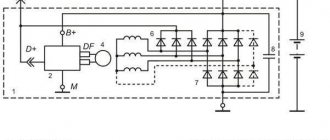
The GU is connected according to the classical scheme. Using the VAZ 2106 generator as an example, let’s consider its functioning. This GU is marked as G-221. It is an AC synchronous electric machine with ELMG excitation. A VB (rectifier) with 6 diodes is built inside the GU.
| 1 | generator rotor winding |
| 2 | generator |
| 3 | generator stator winding |
| 4 | generator rectifier |
| 5 | accumulator battery |
| 6 | ignition switch |
| 7 | battery charge indicator lamp |
| 8 | battery warning light relay |
| 9 | fuse box VAZ -2106 |
| 10 | throttle |
| 11 | temperature compensation resistor |
| 12 | additional resistors |
| 13 | voltage regulator |
A simple and understandable scheme that does not require any subtleties or specific knowledge. On the “six” the PG is located on the engine on the right. It is attached to the tension bar with a nut and to the bracket with its claws.
As you can see, the diagram shows an external regulator. It is marked with the number 13. The generator is indicated with the number 2, the fuse box is indicated with the number 9.
Separately, I would like to consider the relay, which plays an important role in the “six” generator circuit. First of all, it serves to provide information to the driver about the charging status. As is known, it is created by a generating device.
The relay is made on the same principle as all devices that function according to the same properties. The connection is made to terminal 30 of the generator. A separate wire goes through the fuses to the 3Z (lock).
The action of the relay boils down to the following: as soon as the voltage of the BS decreases (falls below the 12-volt value), the relay contacts open, the indicator is activated, giving a sign to the driver.
To better understand the connection diagram, it is recommended that you also familiarize yourself with the principles of battery charging:
- as soon as the key is turned into the 3Z, an electric pulse is supplied to the relay regulator through the fuse (pin 15);
- in the regulator the voltage is transformed and goes further to the positive brush of the GU;
- then, through the brush, the voltage goes to the excitation winding of the GU;
- then - to the negative brush, through which it is brought to ground.
After the relay is activated or after the normal voltage value has been reached in the BS, the GU begins to generate current with the required value. The indicator lamp goes out, and the circuit starts working in factory mode. But when the total voltage drops, the current is not enough, and the contacts open, which leads to the discharge lamp burning.
The constant switching on of the charge indicator lamp indicates that the gene is not working properly. This happens for various reasons. First, you should check the fuses: if they are active, then both relays deserve attention: the regulator and the charger. If they are also in order, then faults must be looked for in the generating device itself.
Before proceeding with replacing the relay, it is recommended to carefully check the functioning of the regulator. The car starts, the speed is kept within the range of 2500-3000 rpm. After this, you need to turn off all current consumers, except the ignition. Then you need to measure the voltage at the battery terminals.
Charging may disappear in the following cases:
- If the generator brushes are worn out.
- In case of malfunction of the generating device.
- If the charging relay is faulty.
- If the rectifier unit (diode bridge) fails.
Thus, installing an external relay-regulator instead of a built-in one will bring a lot of benefits. The fact is that modern charging systems have much more power. Thus, modern memory systems are much more complex than old-style systems.
- Absolutely legal (Article 12.2);
- Hides from photo and video recording;
- Suitable for all cars;
- Works through the cigarette lighter connector;
- Does not cause interference to radios and cell phones.
The VAZ 2106 voltage regulator relay ensures the normal functioning of important vehicle mechanisms and devices. In particular, the adequate operation of the car’s ignition system and its generator, as well as the condition of the battery, depend on it.
Main and additional fuse blocks
| F1 (16A) | Heater fan, rear window defroster, rear wiper and washer system, windshield washer pump |
| F2 (8A) | Steering column switch, windshield wipers, hazard warning lights, breaker relay (in turn signal mode), reverse light, instrument cluster (coolant temperature gauge, fuel level gauge, tachometer, warning lights: turn indicators, differential lock, parking brake, emergency condition of the working brake system, insufficient oil pressure, fuel reserve, battery charge) |
| F3 (8A) | Left headlight (high beam), high beam indicator lamp |
| F4 (8A) | Right headlight (high beam) |
| F5 (8A) | Left headlight (low beam) |
| F6 (8A) | Right headlight (low beam) |
| F7 (8A) | Side light lamps in the left front and left rear lights, license plate lights, side light control lamp |
| F8 (8A) | Side light lamps in the right front and right rear lamps, backlight lamps for the instrument cluster, cigarette lighter, switches, heating and ventilation control unit |
| F9 (8A) | Hazard switch, breaker relay (in hazard mode), tailgate defroster relay contacts |
| F10 (8A) | Sound signal, interior lamps, brake lamps in the rear lights |
| F11, F12 (8A) | Reserve |
| F13 (8A) | Fog light relay contacts in rear lights |
| F14 (16A) | Cigarette lighter |
| F15 (16A), F16 (8A) | Reserve |
| F11 (8A) | Turn signal lamps and relay-breaker for turn signals and hazard warning lights (in hazard warning mode) |
| F12 (8A) | Daytime running light relay, daytime running light bulbs |
| F13 (8A) | Rear Fog Lamps and Relays |
| F14 (16A) | Cigarette lighter |
| F15 (16A) | Spare |
| F16 (8A) | Spare |
| Fuse number and rating | Protected circuit |
| Main unit | |
| 1 (16A)* | Electric windows for front doors Electric side mirrors |
| 2 (16A)** | Air conditioning fan, air conditioning compressor |
| 9 (16A)* | Side mirror heaters |
| 10 (16A)* | Central interior lamp |
| Additional block | |
| 15 (16A)* | Air conditioning fan, air conditioning compressor |
Types of relay regulators
There are two types of them, which work on the same principle, increasing or decreasing the on-board voltage of the car depending on the load.
- A device placed directly on the generator housing and combined with the brush assembly.
- Relay installed separately in the engine compartment. A wire runs through the device from the generator to the battery.
The first type of relay-regulator is only non-separable (the electronic components located inside are filled with epoxy resin). As for the second type, mechanical devices were previously made, but due to reliability they were later abandoned, and today you can find a non-separable electronic version, where the “insides” are also filled with compound.
If your battery does not charge (or the process goes very poorly), or, on the contrary, the light bulbs burn out and the electrolyte boils away, you must first understand whether the voltage regulator is really to blame. This can be done in two ways: directly on the machine or after dismantling the device. Each option is worth considering in more detail.
Testing the removed regulator (with circuit)
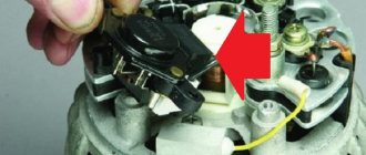
An electronic relay is most often mounted on the surface of the generator next to the generator shaft along which the brushes move, in the area of the generator armature slip rings. The entire combined unit is covered with a plastic cover. It is removed with a screwdriver, the shape of which can be either a cruciform or a hexagon.
Stages of work:
- Unscrew the two fastening bolts and remove the cover.
- We take out the brush assembly.
- We clean it from graphite dust.
- We assemble the circuit using a power supply, charging or a voltmeter. We find a simple 12V lamp from the car, maybe with “dimensions” and wires to connect the entire circuit into one. We use a battery if the charger does not work without it. We connect the wire from it to the regulator, and connect the lamp to the brushes using “crocodiles”. When everything is connected correctly, the lamp will begin to glow because the brush assembly serves as a conductor of electricity from the shaft.
- We raise the charging voltage to 14.5V, the light should go out, since such voltage as a “cutoff” further increases the voltage. By reducing the voltage on the charger, the lamp should light up again. If the voltage rises to 15–16V and the lamp is on, it means the relay is unusable.
Relay-regulator test circuit
Using the same principle, you can check a separate type of regulator of a new type. To do this, you need to disconnect it from the body or cover of the generator and attach it to the circuit. Carry out the check in the same way. As for the old type of relay-regulator installed on kopecks, you need to check it a little differently. Their markings are “67” and “15” . The first contact “67” is a minus, and “15” is a plus. Otherwise the principle is the same.
Interesting on the topic:
relay voltage regulator
New type voltage regulator. How to check. 1 part.
The malfunction of the car generator is classified as critical, in which further operation of the vehicle is not allowed. You can use a multimeter to check the functionality of the generator.
How to test a generator with a multimeter
The diode bridge of the generator can be checked with a multimeter, but you can also use the stand that was used to check the regulator.
But before that, first of all, without removing the rectifier bridge from the generator, connect the red wire of the tester to terminal 30 of the generator, and the black wire to the housing. Set the tester operating mode to dial (diode icon). If it is not there, then set it to 1-2 kOhm. The multimeter should show infinity. If the readings are different, the diode bridge is faulty.
Then check the current rectifiers for breakdown. Leave the positive (red) probe on terminal 30, touch the negative one to the bridge mounting bolts one by one. The multimeter display should show infinity in all cases; any others mean a breakdown.
Next, connect the positive probe to the axle mounting bolts, and the negative probe to the generator housing. In this case, the tester should also output infinity.
But in practice, such verification is most often not enough. In most cases, it is necessary to ring the generator in more detail.
Careful testing
To do this, unscrew the fastening bolts of the rectifier unit, disconnect the copper wires of the stator winding and remove the diode bridge from the generator. Now you can test each semiconductor individually. Before checking, it is advisable to rinse the stabilizer with running water using a medium-hard brush, and then dry thoroughly. For quick drying, a hair dryer is quite suitable.
Attach one of the tester probes to the diode plate, connect the second to the central terminal of each diode fixed to this plate. Then swap the probes. In one case, the multimeter should show infinity, in the other - a nominal resistance of approximately 570-590 Ohms. Rectifiers are considered faulty if:
- In the first and second measurements (when the polarity was changed), the multimeter readings are the same;
- Diode resistance is greater or less than nominal values.
Perform the same actions with the second plate of the diode bridge. If a fault is detected in one or more diodes, it will be easier to replace the entire rectifier unit. True, there are craftsmen who replace failed diodes individually, but such work requires a certain skill and dexterity.
Checking the armature and stator windings
Further inspection requires completely disassembling the generator. First of all, visually check the anchor. Brush rings should not show any blackening, chipping or wear on the treadmills. Blackening and slight wear can be smoothed out with zero-grade emery cloth. Rings with deep grooves must be replaced or, if the thickness of the rings allows, turned on a lathe.
The armature winding should not clearly smell like burning. The color of the winding must be uniform and free of damage and breaks. To check the armature winding for a break, you will need a multimeter. Set the operating mode to continuity testing or resistance measurement and connect the probes to the brush rings. The winding resistance should be within 3-5 Ohms. Then leave one probe on the ring, connect the other to the body. The multimeter display should show infinity.
The generator stator is diagnosed after removal from the housing. First of all, carry out a visual inspection. There should be no visible damage to the wire or its insulation. Then connect the tester wire to the stator housing. With the second wire, touch the terminals one by one. There are only three of them. The tester must be in dialing mode. If the display shows infinity, this indicates that the stator is working properly.
Further testing consists of diagnosing the windings. The resistance of all three windings must be the same.
Before assembling the generator, you need to check and, if necessary, replace the bearings. When turning, they should not jam or make a creaking sound. This means that they are very worn out and will soon fail. Therefore, it is better to replace them immediately.
Repair or replacement?
It is more advisable to buy a new regulator. If it fails, the component parts of the element are seriously damaged. Of course, you can try to restore functionality, but in this case you risk being left with a broken generator somewhere outside the city.
By the way! On VAZ cars, you can try the following method as a temporary measure:
- remove the headlight bulb from the right headlight;
- We install one of its spirals on the terminals removed from the failed regulator.
If everything is done correctly, the emergency lamp will go out, and the one you need will light up and you will be able to get to the service center. However, remember that “folk” methods are used at your own peril and risk.
Diagnosing the regulator requires skillful use of a multimeter, but there is nothing complicated about it. Do not forget to periodically check the performance of this part of the car, and the generator will not give you unpleasant surprises.
Repair of voltage regulator relay on VAZ 2107
Usually the fact that the VAZ 2107 has a voltage regulator is remembered when a problem arises with charging the battery. To be completely precise in the definitions, the voltage relay comes to mind immediately as soon as it turns out that, despite the presence of charging, the battery is almost completely discharged. Let's take a closer look at why a voltage regulator is needed in a VAZ 2107 car. Without going into the intricacies of electronics, the voltage regulator is designed to regulate the voltage at the generator output depending on the engine operating mode. It is quite natural that as the speed changes, the voltage level also changes. And if it drops to 12 volts or lower, the battery stops charging.
Therefore, if you suspect a malfunction in the VAZ 2107 charging system, you must first check the voltage at the battery terminals. This can be done using a regular voltmeter or multimeter (tester). In normal mode, the voltage should be approximately 13-14 volts
If it drops below 13, you should pay attention to the relay; it may need to be replaced
Depending on the type of generator used in the car, the regulator can be internal three-level and external. The internal one is built into the generator and is usually used in VAZ 2105 and 2107 cars, while the external one is used in earlier classic models and is located in the engine compartment on the left arch.
Depending on the type of regulator, replacing it has its own characteristics. Replacing the external regulator is no problem. Using a size 8 wrench, unscrew the two fastening nuts and disconnect the wires from terminals 15 and 67. The new relay is installed in the reverse order. After checking that the wires are connected correctly to the terminals of the regulator, and that its body is in reliable contact with ground, you can start the engine and measure the voltage again to ensure that the fault has been eliminated.
The internal three-level one is somewhat more difficult to change due to limited access to the generator. But, despite this, the task is quite doable even without removing it. Replacing the regulator, as in the case of an external one, comes down to disconnecting the wires and unscrewing two mounting screws using a Phillips screwdriver. After this, the relay is removed from the generator housing. Installing a new regulator occurs in the reverse order. After assembly, the voltage level is checked.
It should be noted that the regulator is not always replaced due to its failure. Recently, more and more often, car enthusiasts have resorted to replacing the generator along with the relay from an old model to a new one. This kind of tuning becomes possible thanks to the complete interchangeability of both models. The reason that prompts car owners to take such a step is the high efficiency that distinguishes the three-level regulator from the standard one.
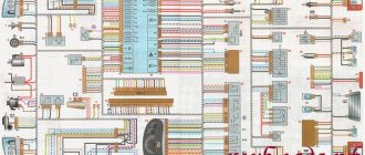
New type relays provide the required voltage level in automatic mode. Plus, it has a wider adjustment range than the standard one, so the battery receives an optimal charge. Under such conditions, the service life of the battery is significantly increased. In the schematic diagram of the electrical circuits of the VAZ 2107 shown below, the relay is indicated by the number 7.
The most common causes of breakdown
- Short circuit of the diode bridge or generator brushes. The result is a shutdown of the generator or a transition to uncontrolled voltage.
- Stabilization voltage shift. In this case, the stability of the voltage is maintained, but it is constantly either low or high.
- Oxidation or burnt contacts.
- Changing the size of the gap between the contacts.
- Relaxation of spring tension.
- Problems with the windings - breaks or short circuits.
Breakdowns can be identified at an early stage - to do this, pay attention to the ratio of fuel consumption to the efficiency of the car. If the car consumes much more fuel than necessary, but performs worse, most likely the problem is in the regulator. A sure sign is the strength of the headlights at night. If, when driving at night, you notice that the intensity of the side lights and instruments has decreased significantly, it’s time to check the regulator.
Methods for self-checking performance
There are several methods for checking the functional state of the regulator. The easiest way is to contact a car service, but you can check the functionality of the device yourself. The simplest way, which is carried out without removing the relay, is to test the on-board current using a multimeter.
Checking with a multimeter without dismantling
The essence of the method is to measure the voltage that goes to the battery to recharge it. During testing, you will need an assistant to use the accelerator pedal to regulate engine speed. The check is carried out as follows.
- Start the engine and warm it up for about 5 minutes.
- With the engine running, open the hood and connect the multimeter contacts to the battery terminals, observing the polarity. Set the tester switch to the 20 volt position.
- The charging voltage coming from the generator is assessed with the low beams on (other current consumers are turned off) and the crankshaft speed within 1.5–2.5 thousand rpm. If the potential difference exceeds 14.8 V, the regulator is faulty and must definitely be replaced. When the incoming current is less than 13.5 V, in addition to the relay, you can suspect a fault in the wiring or the generator itself.
To fully test the relay, it must be removed.
Testing the removed regulator (with circuit)
The electronic relay is usually located on the surface of the generator and is covered with a plastic cover. Removal is done using a screwdriver, the shape of the tip of which depends on the car model (cross-shaped, hexagon). There is a high probability that the regulator forms a block with the generator brushes. For testing, in addition to a multimeter, you will need a 12 V test lamp (no more than 3 W) and an adjustable current source.
We connect the contacts of the wires from the current source:
- “minus” to the regulator mass;
- "plus" to the terminal marked "B".
The test lamp wires are connected to graphite brushes (polarity does not matter).
First, a voltage in the range of 13–13.5 volts is applied to the relay. With such a potential difference, the light bulb should light. If this is not the case, then there is an open circuit in the regulator, which can be anywhere: in any case, the device is faulty.
When the light is on, you need to gradually increase the incoming voltage. If the relay is working properly, within 14.2–14.5 V the light goes out. When the control lamp lights up with a further increase in the potential difference, the relay is faulty (a breakdown has occurred) and must be replaced. An unsatisfactory test result is also when the lamp goes out at a voltage of less than 4 volts. This current will not be enough to provide power to electrical appliances and at the same time efficiently charge the battery.
Pre-check
To check the generator voltage regulator you will need a multimeter. We start the engine and measure the generator voltage with a multimeter. We connect one probe of the measuring device to terminal 30 of the generator (the same pin on the rear wall of the generator, to which there are usually two, sometimes three wires and secured with a nut). The voltage should be between 12.5 - 12.8 volts.
Then we start the engine and again measure the voltage at the generator terminals. At idle there should be at least 13.2 volts, but not more than 14 volts. Then we increase the engine speed to 3500 rpm, in this case the voltage limits should be within 14.2 - 14.5. The voltage should not exceed 14.8 volts. If it is higher, then the battery is being recharged.
Then we turn on the high beam headlights, heater, hazard warning lights and other devices and again measure the voltage at the generator. It will drop under the load of switched on devices, but the voltage value in this case should not be lower than 13.2 volts. If it is below the minimum - “undercharging”.
In both cases, it is necessary to check the voltage stabilizer.
What is it, where is it located, how does it work
This part of the car is responsible for maintaining the voltage of the on-board network within certain limits. The regulator controls the ambient temperature, rotor speed, electrical load level and other parameters. It also protects the sensitive elements of the generator from overloads and is responsible for activating the field winding and other systems.
The product is located directly in the generator. Regardless of the machine model, the principle of operation of the regulator is the same - when the voltage increases or decreases, the component reduces or increases the excitation current to return the indicators to the desired level.
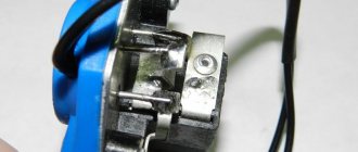
This is what the voltage regulator looks like