Print this article Font size 16
The ignition module on injection VAZ 2109 is deservedly considered one of the most complex electrical components. If the injectors have a module, then the carburetors have the simplest coil.
The actual, but incredibly important task of the module is the generation of high voltage current, which can reach 30 thousand watts. The current follows high-voltage wires to the spark plugs, which create a spark to ignite the air-fuel mixture.
The classic ignition coil is one of the components of the module, so the system works on a much more complex principle than on carburetors.
Where is the ignition module located?
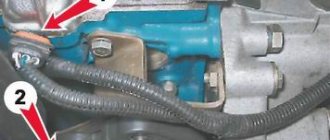
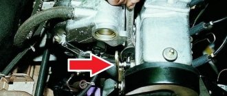
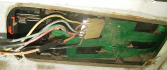
It is placed on a bracket and is attached to it with three nuts, so immediately decide how you will remove the module from the car, either together with the bracket or separately from the bracket (It is easier to remove the module together with the bracket), so let’s get back closer to the topic, the module is located deep in the engine and its location is not very convenient, for clarity, in the photo below it is indicated by a red arrow, and in the photo below one of the spark plugs is indicated by a blue arrow, so first find the spark plugs in the car and then look for yourself a little lower module.
How to check the malfunction of the VAZ 2114 ignition module on your own?
The easiest way to check the device without removing it is to diagnose it at the moment the power unit is tripped. When the motor begins to operate unstably, it is necessary to disconnect the connector elements from each component of the module one by one. If the connector is disconnected from a functioning device, the operation of the engine will change. Dips will appear, and the unstable operation of the unit will increase. When the non-working element of the MH is disconnected, the motor will operate in the same way.
There is another simple diagnostic method, its principle is as follows:
- You will need an assistant to check. The spark plug is removed from the seat. The high-voltage cable is disconnected from the device.
- Then the disconnected wire is connected to a spark plug, which is applied to the body of the power unit.
- The machine motor is starting, you need to make sure that a spark hits the spark plug. If it passes, a blue light will appear between the device and the surface of the power unit, its formation is accompanied by a crackling sound. If there is no spark, then the spark plugs, high-voltage cable and module must be diagnosed.
In the absence of special equipment, diagnostics of the MH can be performed using a control light indicator designed for 12 volts. One conductor from the lamp is connected to the pin of connector A, and the second is connected to ground for grounding. An assistant must start the power unit or rotate the starter mechanism. If the light flickers when performing these steps, then the device is working. Similar actions must be done with another contact.
The channel “Diary of an Auto Electrician” spoke about self-diagnosis of ignition modules, as well as other elements of the system.
Checking the ignition unit with a multimeter
Diagnostics is carried out in the following order:
- The car engine is started.
- The tester switch must be set to DC measurement mode, the limit should be up to tens of volts.
- One of the contacts of the multimeter is connected to connector D on the coil, and the other goes to ground. You can use a car body or a cylinder block as a mass. If there is power, the diagnostic tool display will show 12 volts.
- Then the tester switches to the ohmmeter operating mode, the range of values is up to tens of ohms.
- One contact of the diagnostic tool is connected to output C, and the second goes to ground. If the device is operational, the test will show a value of less than 1 Ohm.
- At the next stage, the tester must be switched to voltmeter mode. The range of values is up to tens of volts.
- One of the contacts goes to the output marked B, and the second is connected to ground.
- If the diagnostics show that the voltage is less than 0.3 volts, then the device is working. This indicates a clear signal passage from the Hall controller. Finally, you can perform a similar test, only with connector A. The results should be identical.
Direct check of secondary coils for breakdown
To diagnose secondary elements of the MH for breakdown, you will also need a tester:
- All connected conductors must be disconnected from the device connectors.
- Diagnostic equipment is set to ohmmeter mode, the range of values is up to tens of ohms.
- The contact probes of the tester must be connected in turn to the paired connectors of the module. For example, in the second and third, as well as in the first and fourth.
- If the diagnostics showed the same results, then all windings are operational. The resistance parameter should be about 5.4 kOhm. If the values obtained are higher, this indicates an internal break in the device. With lower parameters, we can conclude that there is a breakdown.
High voltage wires
Often, the main difficulty when repairing a carburetor VAZ 2109 is the reconnection of high-voltage wires that were previously disconnected from the distributor cover. It's also an ignition distributor.
The difficulty is that many people forget the connection procedure or simply do not know. But in practice, returning high-voltage wires is much easier than understanding the ignition module used on the injection VAZ 2109.
By following a few simple rules, you can easily return the wires to their rightful places.
- The ignition distributor cover is installed in its place, that is, on the distributor, only in a single position. Therefore, even if you wanted to, you won’t be able to confuse anything here. Otherwise the lid simply won't fit.
- There is an installation mark on the cover, which indicates the location of the wire socket from the first cylinder.
- The wires must be connected in the following sequence - 1, 3, 4, 2. Move counterclockwise when looking at the distributor cover from the side of the expansion tank.
If for some reason there are no installation marks on the VAZ 2109 carburetor distributor cover, just follow the connection principle shown in the image.
Repair
Ignition module VAZ 2107
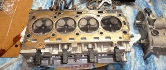
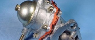
The design of the ignition module is quite complex: it includes one or more coils, a board, contacts and wires. Of all the above elements, only contact connections can be repaired; in some cases, replacement of parts (transistors, coils) is possible.
The module is dismantled and opened for repair purposes. For this you will need:
- Socket wrenches with heads 1, 13 and 17.
- Hexagon 5.
- Screwdriver.
- Soldering iron.
- Flux for aluminum.
- Stranded wire.
- Nail polish.
Opening the ignition module
Repair of the ignition module is carried out in the following order:
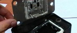
- On the removed device, open the case by prying it off with a screwdriver.
- Remove the silicone film covering the board.
- All aluminum is removed from the explosive contacts.
- On the board, new wires are soldered in place of all the dismantled old ones. To do this, the surface of the collector is cleaned of deposits, after which the board is heated to 180 o C (a characteristic smell will indicate when the desired temperature has been reached). During the soldering process, the ends of the wires are connected to the module.
- At the end of the operation, all contacts, the board and the module are covered with nail polish.
- The device is assembled in the reverse order, installed on the car and the engine is started. In case of normal operation, the ignition module is sealed tightly with sealant, while the wires are tucked inside the cavity so that they are not pinched at the edges by the plate.
If the device does not work, then a breakdown inside the module should be looked for more carefully. The transistor, electronic component may have failed, or there may be a break in the coil. Such a repair makes sense only if its price is significantly lower than the cost of a new part.
Features of the ignition module
Now let's talk about a more complex issue - the ignition module and its design features.
The design includes several components, each of which has its own nuances.
| Component | Peculiarities |
| Ignition coil | There are always two coils on a VAZ 2109. This mechanism is responsible for generating current |
| High voltage switches | Switch keys also work together. Through them, the current goes to the spark plugs, plus the controller regulates the time the current is turned on, which is calculated by receiving information from the crankshaft sensor |
| Electronic control unit | Responsible for distributing information in the form of electronic impulses |
| Frame | High-strength plastic is used for its manufacture, which largely ensures the durability and reliability of the device. |
Ignition coil
Location
Any work related to repair, testing, and maintenance of the ignition module will be impossible to perform if you do not know basic things - the location of the device.
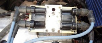
You can find the ignition module (ignition module) in the engine compartment. Find the high voltage wires that go to the spark plugs. One end is connected to them, and the other goes to the module. The MZ is small in size and enclosed in a plastic housing.
Device location
Principle of operation
Initially, on carburetor cars, the system worked due to the presence of an ignition coil. With injectors everything is somewhat different.
- Initially, the ignition coil is turned on, generating a high voltage current. The coil operates on the principle of magnetic induction;
- Then the electronic control unit MZ is connected to the work, performing the functions of control, transmitting commands, and ensuring the flow of current required by the characteristics to the spark plugs;
- Next, the spark plugs activate the spark, ignition occurs, and so on.
MH malfunctions
The ignition module often shows the most basic sign of failure - lack of spark. But this is not the only indicator of a malfunction.
These also include:
- Lack of dynamics when accelerating the car. Trying to quickly pick up speed, you can clearly feel failures in engine operation;
- The engine does not produce the usual power; in some cases, the engine is not able to pull the car uphill;
- The idle speed fluctuates;
- One of the pairs of engine cylinders refuses to work. Here, most likely, there is no current that should come from the ignition coil.
To eliminate problems with the MH, the first thing you need to do is check the spark plugs, and then make sure the other elements are working.
Disconnect and check
Checking the spark plugs
To check the condition of the spark plugs, which may cause the module to malfunction, you need to:
- Unscrew the spark plugs from their seats, having first removed the high-voltage wires. The elements are removed with a special key.
- Inspect the spark plugs for carbon deposits, mechanical defects, and poor clearance.
- Send defective spark plugs to a landfill and install new ones in their place.
If replacing or cleaning the spark plugs does not produce results, then the reason lies in other elements of the ignition module.
Purpose and principle of operation
Ignition module VAZ 2110
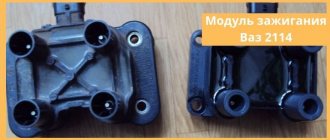
The ignition module of a modern car performs the function of generating high voltage to produce a spark at the spark plugs. It consists of two coils with a closed magnetic circuit and a two-channel switch. Sometimes the switch is made as a separate device, but in most cases it is combined with an electronic control unit for the engine. Externally, the modules differ in the number of wires in the connection connector: a module with a switch has 4 wires, and paired coils have 3.
The ignition module is controlled by the ECU, which supplies constant voltage in the form of low-voltage control signals to the windings of its coils at the right moment. The end of the signal is the beginning of the spark. Thanks to magnetic induction, at the moment of application, a high voltage is generated, creating a spark at the spark plug. The device is located in the engine compartment and can be easily identified by the high-voltage wires leading to the spark plugs.
Methods for preventing the ignition module on a VAZ-2114
Malfunctions of automobile ignition coils on the VAZ-2114 can be avoided if preventive procedures are regularly carried out. These include:
- Periodic unraveling of high-voltage wires (associated with greatly increased internal resistance, as this can damage the module).
- Checking the spark gap between the electrodes of the spark plugs (if the distance between the electrodes changes, this will affect the efficient operation of the ignition coils).
If faulty spark plugs are identified, they are replaced, after which the car will function properly again.
Source
Video “Visual guide to replacing MH”
The STO TONN channel presented a visual aid for replacing the ignition module on a domestic VAZ 2114 car.
Due to a malfunction of the ignition module, the following malfunctions may occur in the operation of the injection engine of VAZ 2108, 2109, 21099 cars: the engine “triples”, “doubles” (works or tries to start on two cylinders), unstable idling, “dips”, “jerks” , “twitching”, etc.
— Multimeter, autotester or other device with ohmmeter and voltmeter modes
— Socket wrenches or heads for “13” and “17”
Preparatory work
— Remove the ignition module from the engine
Disconnect the ends of the high-voltage wires. Use a key set to “13” to unscrew the two upper fastening bolts, and use a key set to “17” to loosen the tightening of the bottom bolt. Remove the module along with its bracket.
The procedure for checking the ignition module (coil) of the ignition system of VAZ 2108, 2109, 21099 cars with an injection engine
In garage conditions, you can check the secondary windings of the ignition module for an open circuit and the primary windings for a short circuit, as well as the voltage supply to the module from the ECU. This is quite enough to diagnose the problem.
— Check for short circuit
The positive probe of the multimeter in ohmmeter mode to terminal “D” of the ignition module connecting block, the negative probe to the bracket (“ground”). If there is no short circuit, the device readings tend to infinity.
How to diagnose the ignition coil on a VAZ-2114
As already mentioned, when the first signs of malfunctions appear in the VAZ-2114 ignition module, the vehicle owner should diagnose it. You can perform a similar procedure yourself at home using the following algorithm:
- Check the spark plugs.
- Check the crankshaft position sensor.
- Check the ignition coil.
At home, all stages of the checks can be performed independently. The first stage is checking the spark plugs. It is carried out in the following sequence:
- We remove the spark plugs from their sockets - remove the tips of the high-voltage wires (a special spark plug wrench is suitable for this).
- We examine the candles.
- We clean them from possible soot.
- We set the correct distance between the electrodes.
- We check the spark plugs for operation using improvised means (for example, from a device made from a piezo lighter) or on a car engine with a working ignition system.
If the spark plugs are in good condition, you can proceed to the next stage of checking for faults in the ignition module.
The second step is to check the crankshaft sensor. This test is carried out using a multimeter, thanks to which two characteristics are checked - voltage and resistance. To do this proceed as follows:
- Remove the crankshaft sensor.
- Measure resistance:
- a special ohmmeter mode is installed on the device;
- the terminals of the device are connected to the ends of the winding, which is brought to the surface;
- with optimal sensor operation, digital readings will range from 500 Ohms to 700 Ohms.
- Measure voltage:
- switch the device to the mode for measuring alternating voltage;
- terminals are connected to the ends of the winding;
- any handy object made of metal should be passed along the body of the crankshaft sensor;
- When the sensor operates optimally, the device will show increased voltage readings because there will be a metal object nearby.
Otherwise, the faulty sensor will have to be replaced with a new one, because it also affects the operation of the VAZ-2114 ignition module. If after this there are still signs of coil malfunction, then you should proceed to the third stage of the test.
The third stage is checking the ignition coil itself. This part is checked as follows:
- The easiest way is to replace the coil with a new one;
- while the car engine is running, you can move the coil and knock on it (if there are visible changes in the functioning, it is time to judge a faulty contact in the coil itself);
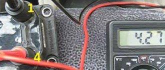
- take measurements with a multimeter for resistance readings, such indicators are taken from paired coils - they should be identical, approximately equal to 5.4 kOhm.
What to do if you don’t have a multimeter, but you need to check the electrical circuit? Experts recommend using a twelve-volt light bulb. To do this, one of the wires coming from it should be connected to the terminal, and the second wire should be shorted to the motor housing. If the control light flickers when the starter starts, then everything is in working order.
If the car owner has problems performing such diagnostics himself, he can always turn to qualified specialists at a service station.