During the operation of a car, problems with the battery and generator often arise. Often, the battery may fail due to insufficient charge. This problem is relevant both for many foreign cars, especially with mileage, and for various domestic cars (VAZ, GAZ, ZAZ, etc.).
For normal operation of a car battery, it is necessary that the generator charges the battery while the engine is running, and neither undercharging nor overcharging of the battery is allowed. Next, we will look at problems with battery charging using the example of a VAZ 2106, the charging relay on this car model, and also how to check the VAZ regulator relay yourself.
What is a charging relay
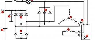
The entire electrical system is powered from two sources:
- Battery - with the engine stopped. It is from the battery that power is supplied to the starter windings when the engine starts.
- Generator set - it is designed to power all consumers when the engine is running. But the primary task is to restore the battery’s charge level, since after starting it loses capacity, and significantly.
The battery voltage is always the same - it can only decrease if charging is not performed.
But a car generator can produce voltage in the range of 10-30 Volts. This is a large range; the electrical system will not be able to cope with such differences. It is the VAZ-2106 charging relay that allows you to stabilize the voltage and prevent overvoltage.
Mechanical problems
Therefore, regardless of whether your car has a carburetor or an injector, it is better not to joke with the generator, but if malfunctions are detected, respond quickly to them.
If the generator stops charging, there is nothing good about it. It is necessary to immediately begin searching for the cause of such a malfunction. Otherwise, all your electrical equipment will be without power, and the battery will soon run out completely.
If the generator works well, then the battery will not need additional charging with special devices for many months, sometimes even years. The battery will consistently retain at least 60% charge. Thus, the batteries are constantly replenishing their charge reserve through the operation of the generator.
Generator design
In any car, including the domestic “six”, the generator consists of the following components:
- The stator is a stationary part; it is attached using threaded connections to brackets on the engine block. The stator has a winding (power), consisting of three equal parts - an alternating three-phase voltage is generated on it.
- The rotor (armature) is a rotating element; it has a winding and two slip rings. Driven by a belt drive from the crankshaft.
- Covers are installed on the rotor at the front and rear. To ensure rotation is as smooth and free as possible, bearings are used.
- The pulley is designed to transmit rotation to the rotor. It is installed on it and is kept from turning by means of a key.
- Brushes allow voltage to be transferred to the winding of the rotating rotor. The VAZ-2106 charging relay circuit also contains a lamp located in the dashboard. Please note that when it burns out, the voltage supply to the excitation winding is stopped.
- Semiconductor diodes rectify three-phase alternating voltage. The output appears as a constant unipolar one.
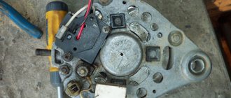
The charging relay on the VAZ-2106, unlike most other cars, is installed on the body, and not in the generator housing. On many modern machines, the voltage regulator and brush assembly are combined in one housing.
Possible generator malfunctions, their causes and methods of eliminating VAZ 2101
| CAUSE | REMEDY METHOD |
| The warning lamp lights up or lights up intermittently when the vehicle is moving. | |
| Alternator drive belt slipping | Adjust the belt tension |
| Break in the connection between plug “85” of the charge warning lamp relay and the center of the generator star | Check and restore connection |
| Charge warning lamp relay misaligned or damaged | Check the relay, adjust it or replace it |
| Open circuit in the power supply circuit of the excitation winding | Reconnect |
| The voltage regulator is misaligned or damaged | Clean contacts, adjust or replace regulator |
| Worn or stuck generator brushes; oxidation of slip rings | Replace the brush holder with brushes; wipe the rings with a rag soaked in gasoline |
| Open circuit or short circuit to ground of the generator excitation winding terminals | Connect the winding leads to the slip rings or replace the rotor |
| Short circuit of one or more "positive" valves of the generator | Replace the generator rectifier unit |
| Open circuit in one or more generator valves | Replace the generator rectifier unit |
| Break in the connection between plugs “86” and “87” of the charge warning lamp relay | Reconnect |
| Open circuit or interturn short circuit in the stator winding | Replace generator stator |
| The warning lamp does not light up when the ignition is turned on | |
| Burnt out filament | Replace the lamp |
| Charge warning lamp relay misaligned or damaged | Clean contacts, adjust or replace relay |
| Open circuit in the connection between plug “87” of the charge warning lamp relay and plug “I” of the fuse box | Reconnect |
| Short circuit of one or more “negative” generator valves | Replace the generator rectifier unit |
| Short circuit of the stator winding to ground | Replace stator |
| The generator is running, but the battery is charging poorly | |
| Weak belt tension; slipping at high speeds and when the generator is running under load | Adjust the belt tension |
| The fastening of the wire lugs on the generator and battery is loose; battery terminals are oxidized; wires are damaged | Clean the battery terminals from oxides, tighten the clamps, replace damaged wires |
| Battery faulty | Replace the battery |
| The voltage regulator is misaligned or damaged | Clean contacts, adjust or replace voltage regulator |
| The battery is being recharged | |
| Poor contact between ground and voltage regulator housing | Reconnect |
| The voltage regulator is misaligned or damaged | Adjust or replace voltage regulator |
| Battery faulty | Replace the battery |
| Increased generator noise | |
| Generator pulley nut loose | Tighten the nut |
| Fan blades are bent | Align the fan or replace it |
| Generator bearings are damaged | Replace bearings |
| Interturn short circuit or short circuit to ground of the stator winding (generator whine) | Replace stator |
| Short circuit in one of the generator valves | Replace the rectifier unit |
| Brushes creaking | Wipe the brushes and slip rings with a cotton cloth soaked in gasoline. |
Video about “Possible generator malfunctions, their causes and methods of elimination” for VAZ 2101
The generator does not charge, how to find and fix the problem.
The reason for the lack of battery charge on the VAZ 2101. How to find
https://youtube.com/watch?v=EGoltTS4LuM
Signs of a faulty car alternator or a quick check of the alternator
Why do you need a voltage regulator?
The main function of the battery charging relay on the VAZ-2106 is to prevent voltage surges at the generator set output. But stabilizing a large current turns out to be not so easy - for this you need to use very massive elements. If in low-current circuits you can get by with installing a zener diode, then with a current of 50-60 Amps this is problematic. But there is a way out - you can stabilize the voltage supplied to the rotor excitation winding.
If you turn to a school physics course, you can find out that the voltage value at the output of the generator completely depends on two parameters - the speed of movement and the magnitude of the magnetic field. In other words, it is necessary that the rotor rotation speed or the magnitude of the magnetic field be constant. Only in this case the voltage at the generator output will not change. But it is impossible to maintain the rotor speed at the same level without the use of special means; one thing remains - to stabilize the supply voltage of the excitation winding.
Connecting a voltammeter DSN-VC288 100 volts 10 amperes. It's simple
Good morning, afternoon and evening Dear DIY masters!
Today I want to tell you about one of the most popular Chinese measuring instruments today, the DSN-VC288 volt-ampermeter. With operating parameters for measuring voltage from 0 to 100V and current from 0 to 10A.
The DSN-VC288 volt-amperemeter, today, is one of the most popular and in demand for measuring voltage and current among radio amateurs and DIYers. Installed on various electrical devices. The price of this device is very budget-friendly. In online stores it ranges from 100 to 200 Russian rubles. Which today can be considered practically a gift.
The DSN-VC288 volt-ampermeter is not very suitable for assembling a laboratory power supply. Since the minimum step for indicating current readings is 10 ma. Incl. It can be placed in a LBP with not too high requirements for the accuracy of measuring the output voltage and current. That is, in a home power supply where very high accuracy is not required.
This device is very easy to connect. This device has two connectors. The 3-pin connector serves to supply power to the device itself. After all, this is an electronic system and also likes to consume electricity, although quite a bit. The power supply of the volt-ammeter fits into a plug from 5 to 30 V. Contact for removing the measured voltage on the load. The measured voltage is the voltage that we will take directly from the load from 0 to 100 V. The third contact is a minus. The 2-pin connector is used to measure the current in the circuit. It is connected to the circuit through the negative in series from the power source to the load. Also on the board of the DSN-VC288 volt-ampermeter there are two trimming resistors. Which serve to calibrate the indication of the measured voltage and current, respectively.
Many who have encountered the above-mentioned measuring device are dissatisfied with the low quality of the calibration trimmers. Here, as they say, some are lucky and some are not so lucky.
As always, a little about safety precautions
This is important, respect electricity, don’t stick your fingers into the socket, don’t measure the voltage with your tongue and it won’t touch you
For those who like to watch rather than read, I suggest watching, with pleasure, a video clip with a detailed description of connecting the DSN-VC288 voltammeter.
Contact regulators
You can still find cars that have mechanical voltage regulators installed. They are extremely imperfect and have a lot of shortcomings, but the owners of such cars are confident that “old is always better.” And every three days they crawl under the hood to adjust the gap and clean the contacts. But using contact systems as an example, it is convenient to consider the principle of operation of regulators as a whole. The essence of the ongoing processes in semiconductor and mechanical ones is somewhat similar.
The design is based on a winding - it magnetizes the metal core. The winding consists of 1300 turns of thin wire. When diagnosing such a relay, you need to know that the resistance of this coil is 17 Ohms. The contacts are made of tungsten. The design includes a shunt and an adjustment plate. There are also several springs and resistors, the latter are switched by mechanical contacts.
Dismantling and removal
How to dismantle the VAZ generator and how to dismantle the device? Which generator is better to install on the VAZ-A 2106?
To restore the VAZ 2106 generator, follow these steps:
Here is a list of actions that should absolutely not be performed during verification:
The functional test should not be carried out during a short circuit or in other words a “spark”; connect terminals of different configurations to each other, and also connect terminal 30 or B + to ground; diagnostics and operation of the generator cannot begin without connected consumers
This is especially important to observe when the battery is disconnected;
Electronic voltage regulators
The VAZ-2106 charging relay was connected to the generator excitation winding. And regardless of whether an electronic or mechanical system is used, it has one purpose - to maintain the voltage at 13.6 Volts. Electronic devices are more stable than mechanical ones and do not require frequent intervention - they do not have mechanical contacts, which sometimes burn out.
One minus is that when using relays and brushes enclosed in one housing, two units will have to be changed at once. But there are regulators that are attached separately from the brush assembly.
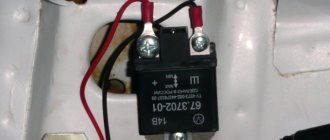
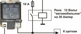
Testing an Individual Relay
Similarly, you can check a new type of regulator, that is, a separate one, here the verification process is much easier. For example, let’s take a model like Y112B; they were installed on many domestic cars before (VAZ).
This is a separate element, so we simply unscrew it from the body (sometimes from the generator cover) and attach it to our stand. Once again, I would like to remind you that it is advisable to have a 12V power supply, then the testing process will be much easier. If not, we use a charger (with adjustment modes) and connect it according to the lower diagram.
The check is the same, we increase the voltage to 14.5 V, the lamp should go out, if not, or turns off at a voltage much higher, then the relay has failed and needs to be replaced.
How to check the regulator
Every motorist should know how to check the VAZ-2106 charging relay. Main conditions:
- A voltage of less than 14 Volts must pass through the device. For diagnostics, power from the car battery is connected to it.
- If the voltage is above 14 Volts, then it should not pass through the regulator. To check the circuit, the elements are connected, and the car battery and, for example, two AA batteries connected to it in series are used as power.
The main sign that the VAZ-2106 charging relay has failed is the voltage at the battery terminals is below 13.6 Volts.
Each car is equipped with a voltage stabilization device. On the “sixes” a VAZ 2106 generator voltage regulator relay is installed. The task of the device is to maintain the voltage level of the on-board network.
Relay installation and connection
How much should the generator produce to properly charge the battery?
Always work from the device to the batteries. First connect the cables to the relay, then install the fuse, and only then connect the cable to the battery. This sequence is safer than connecting from batteries to the device
All cables running directly from the batteries must be fused. They protect the cable from fire, which can occur when a damaged positive conductor comes into contact with the hull of a car or boat. Fuses are placed as close to the battery terminals as possible so that most of the cable is protected.
The fuse rating is chosen to be 30-50% greater than the relay rating. For example, a device rated at 100 amps will require a 130-150 amp fuse. Many relays are designed to withstand an overload of 600% of the nominal value, but withstand this current for only a few milliseconds
| Charging current | Minimum cable cross-section, mm2 | Fuse rating, A |
| 50 | 10 | 75-80 |
| 70 | 16 | 80-90 |
| 90 | 25 | 125-130 |
| 110 | 35 | 150 |
| 120 | 50 | 150-175 |
To protect the cable from batteries, fuses ANL, MRBF, MIDI / AMI are suitable for the relay. A 5 amp fuse is sufficient for the signal conductors.
Purpose of the device
The generator voltage depends on the following factors:
- Rotor speeds.
- Current load.
- Magnetic flux values.
A sufficient condition for the generation of electrical energy is the rotation of the rotor of the VAZ 2106 generator in a magnetic field. Magnetic flux crosses the stator windings. AC voltage is generated. The generator diodes rectify the current.
The role of the electromagnet is performed by the excitation winding. It is laid in the grooves of the rotating part. The excitation voltage is supplied to it through the brush assembly. By changing the strength of the current passing through the winding, generation is controlled.
The VAZ 2106 (RR) voltage regulator controls the rotor winding current. The block changes the resistance of the excitation circuit depending on the network voltage level. The generator responds as expected. This way the device returns the generator voltage to normal.
Increased demands are placed on the operation of the control unit. They are determined by working conditions and technical characteristics of consumers. All equipment that is connected to the passenger vehicle network is designed for 12 volts (V). The VAZ voltage regulator must maintain a range from 13.2 to 14.4 V. This gap should not depend on the number of rotor revolutions and ampere load.
The voltage regulator relay should turn on automatically after starting the engine. In addition to its main purpose, the device performs additional functions:
- protects the generator from overloads;
- recharges the battery;
- protects devices from overvoltage.
Add. equipment: Installed a digital voltmeter in the VAZ-2107 panel
After problems with the generator and unstable voltage, I decided to install a digital voltmeter to monitor the voltage in the car's on-board network. To do this, I ordered a car voltmeter with an LCD screen from Aliexpress that can be built into the panel.
I decided to install it in place of the standard radio, since my radio was moved upstairs.
- The wires are yellow (there was no red) and black, 2 meters each, with a cross-section of 1 mm, maybe smaller
- Plastic plug for the radio receiver where the voltmeter will be inserted
- Switch to prevent battery drain
- Male-female and ground terminals
- Heat shrink tube set
- 10A fuse
- Handy tools and soldering iron
We will connect it directly to the battery terminals for a more accurate measurement, according to this scheme:
There is a mistake in the video and the wrong diagram is indicated - the button and fuse should be on the “positive” wire (!).
We solder the terminals to the wires, insulate the contacts with heat-shrinkable tubing, you can also use connector chips.
I’m not soldering the ground terminals yet, since I’ll have to pull the wires through the under-torpedo space into the engine compartment - I’ll solder them on site.
In the plastic plug we cut out holes for the sensor and button.
We collect everything, it turned out something like this.
We pull the wires under the panel and through the engine shield to the battery. Yellow (red) goes to the “+”, black to the “-” battery. We leave a small margin in length in the center console for ease of removal of the entire structure.
Now we solder the ground terminals to the wires and screw them to the battery terminals.
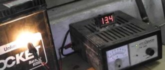
We check the readings using a multimeter through the cigarette lighter. We make a mental correction of about 0.1 Volt to the readings due to the loss of voltage in the wires - this means we have 12.4 Volts at the battery terminals.
Done, now there is no need to constantly carry a multimeter with you.
Types of structures
There are 2 types of regulators: old and new. They replace each other, although they contain different fillings. The old design is equipped with a mechanical relay. VAZ cars are equipped with a voltage regulator of the PP-380 type. Devices of this series use moving contacts to switch on resistors.
This spare part has been removed from mass production. Nowadays such specimens are rare. The vibration regulator PP-380 also has a number of disadvantages. Let us point out the difficulties in operating the contact option:
- need for customization;
- step adjustment;
- periodic cleaning of the contact group;
- low reliability;
- creates radio interference;
- short service life.
Today, semiconductor technologies have replaced the outdated model. Cars produced by VAZ, GAZ, UAZ are equipped with electronic developments. The innovation is a huge merit and success of Russian manufacturers.
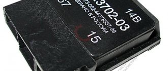
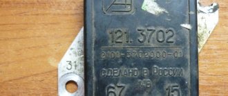
Regulators based on transistors are classified as non-contact relays. VAZ 2106 received a block of type 121.3702. The radio components are housed in a rectangular plastic case.
Installation specifics
Table of characteristics of a digital voltmeter.
If there are no problems during installation with digital voltmeters that are powered from the cigarette lighter, then models installed directly into the dashboard often force drivers to think about the order in which they are connected.
Most voltmeters on the market have two or three wires for connecting to the network, although there are models with four contacts. The wires have standard color markings:
- the red wire corresponds to “plus”;
- the black wire is connected to the negative;
- The white wire is responsible for controlling the backlight intensity and turning the device on and off.
In some cases, an unexpected problem arises when connecting the voltmeter in this way: it lights up dimly or refuses to work at all. The reason may be the alternative marking of the wires, in which the white wire is responsible for the “minus”, and the black wire for controlling the device.
The voltage sensor is installed in the standard place of the clock, but in some cases, when it is impossible to find free space for the voltmeter, you have to make a hole for it directly in the dashboard.
An excellent place to connect the device is the dashboard plug on the left side of the steering wheel. It is small in size and easy to remove and secure for processing.
Figure 1. Connection diagram for a voltmeter with a pulse stabilizer.
The voltmeter body has a raised surface: the frame around the display will protrude above the surface of the car panel. Thanks to this, the device will not fall inside the mounting socket, and will also hide uneven edges of the hole.
Inexpensive models of voltmeters may not have a separate wire for power; such a device is connected via three contacts on the sensor body (Fig. 1). In this case, the voltmeter is connected using a 4-wire wire from the computer drive (Fig. 2). The wide IDE format connector is cut off, and the remaining wiring is attached by soldering to the contacts of the car wiring. The 4-pin contact ensures a good connection and makes it possible, if necessary, to quickly and effortlessly replace the voltmeter if it breaks down.
Regardless of the structural features of the voltmeter, before installing it, the car’s wiring diagram is studied in detail, according to which the location of the device’s connection is determined. It would also be a good idea to carefully read the instructions for the device, since the methods for connecting it may differ.
Device diagnostics
A malfunction of the charging circuit elements can be detected while driving. With the engine running, look at the instrument panel. When the voltage drops, the charging relay turns on the light. The alarm indicates a possible failure of the PP.
To check the voltage regulator, you need a voltmeter. The tester can be purchased at a store or borrowed from a familiar electrician. The mode switch is set to the limit of 20 V. The common wire (black) is connected to the ground of the passenger car, and the red probe is placed on the “+” sign of the battery.
You can check the relay regulator with the engine running and the battery fully charged. The sequence of actions to diagnose the device should be as follows:
- Use the ignition key to start the engine.
- Turn on the load (high beam headlights).
- Warm up the engine for 15 minutes.
- We set the rotation speed to 2.5 thousand using the tachometer.
- We take tester readings at the battery terminals.
After completing all the points, an analysis is carried out. If the needle on the instrument scale is within 14.2 V, then the regulator copes with its task. In this case, the voltage should not significantly depend on the number of revolutions.
Deviation of indicators from the norm indicates a breakdown of the regulator.
Remember that the electronic relay does not allow the terminals to be removed from the battery while the engine is running. This leads to voltage surges and failure of electronic devices.
Electrical circuits of the VAZ 2106 car
Its design consists of a pair of brushes made of graphite, springs that allow them to be pressed more tightly to the rings on the rotor, as well as a brush holder. Loosen and remove the drive belt. Disconnect the block with wires from the generator connector. Contents: How to connect a standard generator G Replacing a VAZ generator with a G Refining the generator G for a VAZ Checking the functionality of the power supply system Electrical diagram of a VAZ As a matter of fact, if we look at the electrical diagram of a VAZ, which we have given below just in case, it turns out that it differs only from the diagram the presence of additional electrical appliances, which entailed some changes. Conclusion Now you know what elements the VAZ generator consists of
The rectifier unit looks like a large horseshoe into which semiconductor elements are pressed. Consequently, electrical energy is generated. To do this, it is necessary to de-energize all current consumers of the car and increase the engine speed to 2.5 thousand.
Therefore, install a mudguard that will protect your car from moisture.
No generator can do without a rectifier unit and a voltage regulator. In this case, significant current flows through the valves and they are damaged. How is it better than the standard six? GENERATOR VAZ 2101 BATTERY CHARGING LAMP AND PRINCIPLE OF OPERATION
Read more: Measuring electrical laboratories
Connecting the unit
Before discarding the device, you should make sure that other parts are in good condition. The belt, alternator, battery, and wires are subject to inspection. The lack of charging of the VAZ 2106 may be caused by a loose belt. If the unit was removed before checking, you should make sure that the wires are connected correctly.
Replacing the voltage regulator is done in a garage. Even an inexperienced driver can do this. You will need a tool, skillful hands and a little knowledge.
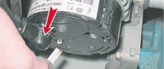
Open the hood to find the remote relay. In the Zhiguli, the box is attached with lugs to the left wing. We find the object near the brake fluid reservoir. Some relays are built into the generator housing. People call them integrals.
Do not rush to remove the wiring from the terminals. Experienced car enthusiasts are advised to first mark the wires with a marker. There are 2 gray and orange wires suitable for the VAZ voltage regulator. They are attached to terminals numbered 67 and 15. Do not mix up the wires. The gray color corresponds to the number 67, and the orange color corresponds to 15.
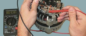
How to test a generator with a multimeter
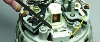
The diode bridge of the generator can be checked with a multimeter, but you can also use the stand that was used to check the regulator.
But before that, first of all, without removing the rectifier bridge from the generator, connect the red wire of the tester to terminal 30 of the generator, and the black wire to the housing. Set the tester operating mode to dial (diode icon). If it is not there, then set it to 1-2 kOhm. The multimeter should show infinity. If the readings are different, the diode bridge is faulty.
Then check the current rectifiers for breakdown. Leave the positive (red) probe on terminal 30, touch the negative one to the bridge mounting bolts one by one. The multimeter display should show infinity in all cases; any others mean a breakdown.
Next, connect the positive probe to the axle mounting bolts, and the negative probe to the generator housing. In this case, the tester should also output infinity.
But in practice, such verification is most often not enough. In most cases, it is necessary to ring the generator in more detail.
Careful testing
To do this, unscrew the fastening bolts of the rectifier unit, disconnect the copper wires of the stator winding and remove the diode bridge from the generator. Now you can test each semiconductor individually. Before checking, it is advisable to rinse the stabilizer with running water using a medium-hard brush, and then dry thoroughly. For quick drying, a hair dryer is quite suitable.
Attach one of the tester probes to the diode plate, connect the second to the central terminal of each diode fixed to this plate. Then swap the probes. In one case, the multimeter should show infinity, in the other - a nominal resistance of approximately 570-590 Ohms. Rectifiers are considered faulty if:
- In the first and second measurements (when the polarity was changed), the multimeter readings are the same;
- Diode resistance is greater or less than nominal values.
Perform the same actions with the second plate of the diode bridge. If a fault is detected in one or more diodes, it will be easier to replace the entire rectifier unit. True, there are craftsmen who replace failed diodes individually, but such work requires a certain skill and dexterity.
Checking the armature and stator windings
Further inspection requires completely disassembling the generator. First of all, visually check the anchor. Brush rings should not show any blackening, chipping or wear on the treadmills. Blackening and slight wear can be smoothed out with zero-grade emery cloth. Rings with deep grooves must be replaced or, if the thickness of the rings allows, turned on a lathe.
The armature winding should not clearly smell like burning. The color of the winding must be uniform and free of damage and breaks. To check the armature winding for a break, you will need a multimeter. Set the operating mode to continuity testing or resistance measurement and connect the probes to the brush rings. The winding resistance should be within 3-5 Ohms. Then leave one probe on the ring, connect the other to the body. The multimeter display should show infinity.
The generator stator is diagnosed after removal from the housing. First of all, carry out a visual inspection. There should be no visible damage to the wire or its insulation. Then connect the tester wire to the stator housing. With the second wire, touch the terminals one by one. There are only three of them. The tester must be in dialing mode. If the display shows infinity, this indicates that the stator is working properly.
Further testing consists of diagnosing the windings. The resistance of all three windings must be the same.
Before assembling the generator, you need to check and, if necessary, replace the bearings. When turning, they should not jam or make a creaking sound. This means that they are very worn out and will soon fail. Therefore, it is better to replace them immediately.
Diagnosing charging relay faults
- Worn generator brushes. If the length of the generator brushes of the VAZ-2106 car becomes insufficient, the charge may be lost. When diagnosing a malfunction, you should first carefully check the condition of the brushes in the generator. Their length should not be less than 12 millimeters. If it does not meet the minimum requirements, then they need to be replaced.
- The diode bridge of the generator does not work. Failure of one or more elements of the rectifier unit may cause a charging malfunction. You should use a tester to check the serviceability of all diodes.
- Circuit breakers. If there is no charging current in the VAZ-2106 car, it is worth checking the fuses. If a burnt one is found, it should be replaced.
- Alternator belt and its tension. The generator belt is made in the shape of a wedge, so it is bursting between the cheeks in the pulley. When the pulley wears out, the generator belt may slip in the cheeks. Because of this, charging problems sometimes occur. In this case, it is necessary to immediately replace the generator pulley and belt.
- Battery terminals. If there is oxidation on the battery terminals, it may prevent the battery from charging. In this case, you should clean the terminals with soda dissolved in water. This product can remove plaque. After completely cleaning the terminals from oxidation, wipe them well with a dry cloth and then lubricate them with thick lubricant.
Unsustainable breakdown - hurry up with repairs!
It would seem that there is something wrong here - there is not enough tension. The car runs on gasoline, not electricity. However, a lack of current power leads to an increase in fuel consumption, a decrease in engine power, and some electrical appliances stop working altogether and will require replacement in the future. This is especially noticeable in the dark, when many power supply devices are used.
You can deal with this problem easily and quickly by charging it properly. However, sometimes this doesn't help. Look under the hood - the battery terminals may be loose or oxidized. If in a parking lot the current still maintains a constant voltage, then during driving, due to vibration, the terminals may move away, opening the circuit. To fix the problem, you need to thoroughly lubricate the fasteners and tighten the bolts; sometimes only replacing the old terminals with new ones will help.
Connection diagram for the VAZ-2108 generator
The VAZ-2108 generator has a rather massive stator winding, since it uses a large cross-section wire. It is with its help that electricity is generated. The wire is wound evenly over the entire inner surface of the stator into recesses specially provided for this purpose in the magnetic core. It’s worth talking about the latter separately. The middle part, the generator stator, consists of a series of thin metal plates pressed tightly together. They are often boiled on the outside to prevent separation.
goes out the reasons for the loss of charging on the VAZ For
Mitsubishi Carisma Logbook The battery charging light is on, but there is charging, what is the reason
2106 checking the electrical circuit of a car, you need a simple multimeter or voltmeter. The most common causes of loss of charging voltage are:
- are low tension on the alternator belt or wear;
- generator malfunction (deterioration, malfunction of diode bridge brushes, breakage or burnout of stator or armature coils);
- voltage regulator malfunction;
- break in the charging circuit.
The most common cause of charging failure is a faulty relay voltage. In order to check its functionality, it will be enough to remove both wires from it, connect them together, and start Pri. engine provided that all other circuit elements are suitable, the voltage in the circuit will approximately reach 17 V or more. If the voltage is not necessary, then check for the presence of +12 V at the terminal, the output to the connected 15 relay-regulator. If it is missing, check the fuse responsible for the circuit and the integrity of this circuit itself.
If there is power at this terminal, then you need to check the connections in the excitation circuit of the generator. Connect a +12 V battery test lamp between the battery and the wire that is connected to relay 67 terminal of the voltage regulator. In this way, you can also check the voltage relay circuit, and check the serviceability of the generator brushes and its armature windings. If there is no voltage at the terminals, the lamps assume that the rectifier bridge is faulty.
Next, check the serviceability of the conductor from the generator to the relay. To control such a test, it is necessary to disconnect the generator from the terminal and connect it to -12 V. The glow of the control lamp indicates faulty brushes or a broken armature of the windings. If you suspect a generator malfunction, remove it from the car and perform a complete disassembly. Next, check the serviceability of each diode in the diode generator bridge, perform a continuity test of the stator coils and check for a break or burnout in the armatures. Faulty elements are repaired or replaced.
The VAZ 2106 battery charging circuit provides for the presence of a constant voltage, regardless of 13.5 to 14.3 V, depending on engine speed. However, there are times when at medium engine speeds the voltage drops “noticeably” when an additional load is turned on. If such a phenomenon occurs, it is necessary to check the tension of the generator belt and adjust it. Weak terminals on the battery contact sometimes also lead to this effect.
If the voltage at the battery terminals is higher than the specified limits, you need to check all the contacts, starting from the positive terminal of the battery to the voltage regulator-relay. If all contacts are in the relay, then the regulator must be replaced.
Timely maintenance of the electrical equipment of the car, the condition of the contacts and terminals of the battery, regular checking of the belt tension and electrolyte level in the battery will allow your car’s engine to operate for a long time and without problems, and you will avoid many malfunctions on the road.
Measuring circuit voltage using a voltmeter
The voltmeter device helps measure the potential difference in an electrical circuit. To minimize the impact on the network, the device should have the highest possible resistance. It determines the measurement error and sensitivity of the device. In the process of improvement, voltmeters have gone from point-type, analog instruments to discrete ones with digital indicators. Voltage measurement has become an integral function of most multimeters and electronic oscilloscopes. Voltage measurement and indication are used in some extension cords, residual current devices and circuit breakers.
Checking the electrical equipment of the UAZ if the battery charge is lost
The UAZ Patriot has two current sources to power all electrical equipment - a battery and a generator. The battery is used when starting the engine and to supply 12 V electric current to the starter and other consumers when the engine is not running. When the engine is running, the main source of current is the generator; it provides electric current to all consumers, including the ignition system, and charging the battery.
If the battery discharge warning light is on in the instrument cluster, it means that current is not flowing from the generator to the on-board network and the battery's energy reserves are being consumed. Operating a vehicle with a low battery warning light on is unacceptable, as sometimes the cause of the light coming on may be a short circuit in the wiring, leading to a fire in the engine compartment.
Stop the car, turn off the engine and determine what fault caused the warning light to come on. If the cause of the malfunction is not a short circuit, and the battery is fully charged, you can drive to the repair site without a generator, but it is better to try to fix the malfunction on the spot.
The procedure for checking the electrical equipment of the UAZ Patriot in the event of a lack of battery charge.
1. Check to see if the accessory drive belt is broken. If a break occurs, replace the alternator drive belt.
2. If the belt is intact, check and, if necessary, adjust its tension.
3. If the warning light remains on, slide off the rubber protective cover of the plus terminal of the battery. Check the wires connected to the plus and minus terminals of the battery.
4. Check the wires connected to the starter and generator. They may be torn, broken off inside the insulation, or have oxidized or unreliable contacts.
5. If there is a malfunction, correct it and start the engine. If charging current appears, you can continue driving.
6. If, after taking measures, the warning light continues to light while the engine is running, then the possible cause of the malfunction lies in the generator itself.
There may be several reasons for a generator malfunction and it is better to eliminate them in a car service center or garage, and you just have to hope that the energy reserve in the battery is enough to get to them.
In order to reduce current consumption when driving a car with a faulty generator, if possible, turn off the audio system, unnecessary lighting devices, air conditioning, heater fan, heated rear door glass, etc.
Connection diagram for the VAZ-2109 generator
- Alternator. The 37.3701 or 94.3701 series can be installed.
- Negative diode.
- Additional diode.
- Positive diode.
- Alternator warning lamp, also known as battery discharge lamp.
- Instrument cluster.
- Voltmeter.
- Relay and fuse box located in the engine compartment in the compartment between the engine and the vehicle interior.
- Additional resistors built into the fuse mounting block.
- Ignition relay.
- Egnition lock.
- Accumulator battery.
- Capacitor.
- Rotor winding.
- The voltage relay is located in the engine compartment.
Connection diagram for the VAZ-2110 generator
On VAZ-2110, 2111 and 2112 cars, a 94.3701 generator was installed with a maximum output current of 80 Amperes and a voltage = 13.2–14.7 Volts.
Here is a breakdown of the connection diagram for the generator on the ten :
- Battery 12V;
- generator 94.3701;
- mounting block;
- egnition lock;
- battery charge indicator lamp in the instrument cluster
Tips and tricks
A common culprit for malfunctioning regulator relays may be oxidation of its terminals. This oxidation results in significant voltage loss. In this case, it is necessary to thoroughly clean the contacts and recheck. The voltage reading at the contacts should be similar to those given by the battery itself, that is, there should be no noticeable losses. Reduced voltage at the contacts indicates that they should be cleaned, and the regulator itself is often in working order. After cleaning, the terminals can be additionally treated with special chemicals that prevent further oxidation.
Finally, I would like to add that the cost of the regulator relay is not high. One of the surest ways would be to replace it with a new element if malfunctions are detected in its operation. Moreover, integrated relay regulators are a part in a monolithic housing that cannot be disassembled for repairs. Savings on this device are not justified, since rapid battery failure or a significant reduction in battery life will entail more serious costs when it is necessary to replace the battery.
Analog and digital devices
Analog devices are based on electromagnetic, magnetoelectric, and electrodynamic systems. Similar types of designs are incorporated into ammeters. To increase the measurement limits, shunts are used. After the measurement, it is necessary to take into account the resistance of the additional resistor in the resulting result.
The design of a digital voltmeter is based on an ADC. The measurement accuracy is determined by the sampling with which the analog-to-digital converter operates. The voltmeter indicator displays the finished result in digital form, which greatly facilitates working with the device. The impact on the network for such devices is minimal due to the presence of their own power source.
The widespread use of discrete voltmeters has led to their integration into other devices. Most multimeters have the ability to measure DC and AC voltage. At the same time, to increase the accuracy of measurements, several limits are provided in the design. The high resistance of the voltmeter allows you to reduce its influence on the circuit to which the measuring device is connected.
How to identify a blown fuse
There are two ways:
- visual inspection;
- diagnostics with a multimeter.
Visual inspection
It is necessary to check the integrity of the metal partition of the element. If it is broken, then the insert is burned out.
Diagnostics with a control and a multimeter
When an element burns out, the integrity of the jumper is not always compromised. It wouldn't hurt to check with a multimeter. The probe is applied to the fuse, the device is turned on, and if it shows resistance other than 0 Ohm, then the element is broken.