Print this article Font size 16
Many of you probably remember from school about such a concept as the Hall effect . If you forgot, then it reminds you. If electricity constantly flows in a conductor, and this conductor is placed in a magnetic field, a potential difference will appear.
This principle forms the basis for the functioning of the hall sensor, which is used, among other things, on the VAZ 2110 car.
The principle of operation of the sensor and its features
In its operation, the sensor uses the physical Hall effect, discovered in the 19th century. However, they began to use it only in the 70-80s of the last century, when automakers began to switch from contact ignition systems to electronic ones.
The principle of operation of the sensor is quite simple. As the motor shaft rotates, metal blades pass through slots in the motor housing. It gives an electrical impulse to the switch, as a result of which the latter unlocks the transistor and supplies voltage to the ignition coil. It, in turn, converts the low-voltage signal into a high-voltage one and supplies it to the spark plug.
Structurally, the sensor has three contacts:
- for connection to “ground” (car body);
- to connect voltage with a “+” sign and a value of about 6 V;
- to supply a pulse signal from it to the switch.
The advantages of using a Hall sensor in electronic ignition systems are two main factors - the absence of a contact group (which constantly burns out), as well as a higher voltage on the spark plug (30 kV versus 15 kV).
Since Hall sensors are also used in braking and anti-lock braking systems and tachometer operation, the device performs the following additional functions for the car:
- increases engine performance;
- speeds up the functioning of all machine systems.
As a result, the ease of use of the car, as well as its safety, increases.
Hall sensor for VAZ 2107
Hall sensor for VAZ 2109
Hall sensor for VAZ 2110
Briefly about the principle of operation
The principle of operation of the ignition sensor is based on the Hall effect, which received its name in honor of the American physicist who discovered this phenomenon in 1879. By applying a constant voltage to the edges of a rectangular plate (A and B in Fig. 1) and placing it in a magnetic field, Edwin Hall discovered a potential difference at the other two edges (C and D).
Fig.1. Demonstration of the Hall effect
In accordance with the laws of electrodynamics, the Lorentz force acts on charge carriers, which leads to a potential difference. The Hall voltage value is quite small, ranging from 10 µV to 100 mV, it depends on both the current strength and the electromagnetic field strength.
Until the middle of the last century, the discovery did not find serious technical application until the production of semiconductor elements based on silicon, ultra-pure germanium, indium arsenide, etc., with the necessary properties, was established. This has opened up opportunities for the production of small-sized sensors that can measure both field strength and current flowing through a conductor.
Signs of a Hall sensor malfunction
Sensor failures manifest themselves in different ways . Identifying them can sometimes be difficult even for an experienced master. Here are some of the most common symptoms and problems with the Hall sensor:
- starts poorly or does not start at all;
- occurrence of interruptions in engine operation at idle speed;
- “jerking” of the car when driving at high speeds;
- The engine stalls while the car is moving.
If your machine has one or more of these symptoms, it is imperative to check the sensor.
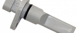
Hall sensor VAZ 2110 injector 8 valves
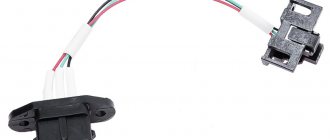
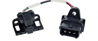
The Hall sensor (camshaft position sensor) is an important element on cars with fuel injection. If it fails, then the car can no longer be started. To avoid such an unpleasant surprise along the way, you need to monitor what condition it is in and change it in time. The article describes how to check the Hall sensor, signs of a malfunction, and also provides step-by-step instructions on how to replace the device on a VAZ 2110 injector.
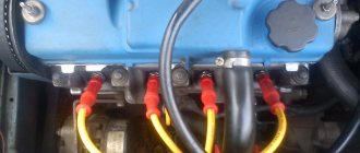
The Hall sensor is an integral part of the distributor and is a magnetically conductive plate with a number of slots equal to the number of cylinders in the power unit. As the shaft rotates, metal plates pass through a slot in the device. As a result, a pulse voltage arises, which is transmitted to the coil, where it is converted into a higher voltage and supplied to the spark plugs.
The device is equipped with three terminals:
- one is connected to the vehicle’s ground and is “negative”;
- the second is a plus with a supply voltage of 6 V;
- from the third, a pulse signal is transmitted to the switch.
Hall sensor for car [Hide]
How to check the Hall sensor
There are several verification methods . Briefly, they work like this:
Checking the serviceability of the hall sensor (diagram)
- Creating a simulation of the presence of a Hall sensor . This method of checking is the fastest and is suitable if there is power at the ignition system components, but there is no spark. For this purpose, the three-pin block is removed from the distributor. Next, you need to turn on the car’s ignition and connect (short with a piece of wire) outputs 3 and 2 (negative pin and signal contact). If during this process a spark appears , it means the sensor has failed . Please note that in order to detect sparking, you need to hold the high-voltage wire near ground.
- Checking the Hall sensor with a multimeter is the most common method. For this check, a multimeter (tester) is used. To do this, it is enough to measure the voltage at the output of the sensor. then the voltage should be within 0.4...11 V.
- Replacing a faulty device with a known working one . You can borrow it from friends who have a car with the same sensor. If after replacement the problems that bother you disappear, you will have to buy and replace the Hall sensor with a new one.
Another common method is to check for resistance at the sensor . To do this, you need to make a simple device consisting of a 1 kOhm resistor, an LED and flexible wires. A resistance is soldered to the LED leg, and two wires of a length that is convenient for operation (not short) are soldered to it.
Then remove the distributor cover, disconnect the distributor and plug box. Next, check the serviceability of the electrical circuit. To do this, an electronic multimeter (voltmeter) is connected to terminals 1 and 3, after which the car’s ignition is turned on. Under normal conditions, the value obtained on the screen of the measuring device should be within 10...12 V.
Next, we similarly connect the constructed device to the same terminals. If you guessed the polarity correctly, the LED lights up. Otherwise, the wires must be swapped. The further procedure is as follows:
- do not touch the wire connected to the first terminal;
- We transfer the end from the third terminal to the free second;
- rotate the camshaft (manually or using a starter).
If the LED blinks while the shaft is turning, then everything is in order and the Hall sensor does not need to be replaced.
It is worth noting that the process of checking the Hall sensor on the VAZ 2109, Audi 80, Volkswagen Passat B3 and other cars is carried out according to the same scheme. The only difference is the location of individual parts under the hood of the car.
Elements of the VAZ-2110 ignition system
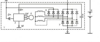
The ignition system of the VAZ-2110 is contactless or microprocessor-based. This section discusses the contactless ignition system. It consists of a distributor, commutator, ignition coil, spark plugs, ignition switch and high and low voltage wires.
Fig.28. Scheme of the contactless ignition system of the VAZ-2110
1 – battery; 2 – generator; 3 – plug connector; 4 – ignition switch; 5 – sensor-distributor; 6 – switch; 7 – candles; 8 – ignition coil.
Ignition distributor (distributor) VAZ-2110 type 40.3706 or 40.3706-01, four-spark, unshielded, with a control pulse sensor (Hall) and built-in vacuum and centrifugal ignition timing regulators.
Fig.29. Distributor of the ignition system VAZ-2110
a – device; b – diagram of the operation of the centrifugal regulator; 1 – coupling; 2 – body; 3 – vacuum regulator; 4 – vacuum regulator rod; 5, 7 – covers of the vacuum regulator; 6, 12 – springs; 8 – fitting for supplying vacuum; 9 – diaphragm; 10 – centrifugal regulator; 11 – contactless sensor; 13 – driven plate of the centrifugal regulator with screen; 14 – roller with the drive plate of the centrifugal regulator; 15 – weights; 16 – oil seal; 17 – cover; 18 – rotor; 19 – protective screen; 20 – holder of the front roller bearing assembled with the sensor support plate; 21 – washer for fastening wires; 22 – sensor support plate with bearing.
The VAZ-2110 distributor performs two main functions: firstly, it sets the moment of spark formation depending on its initial installation, the number of revolutions of the crankshaft and the load on the engine, and secondly, it distributes high voltage pulses (“spark”) among the cylinders in accordance with the order of their work. For this purpose, a rotor (runner) mounted on the distributor sensor roller is used.
In order to avoid mistakes during assembly, the slider and ignition distributor cap are installed on the distributor sensor in only one position, as well as its shaft. The slider contains a 1 kOhm noise suppression resistor.
Fig.30. Scheme for checking the Hall sensor on a VAZ-2110 car
1 – ignition distributor; 2 – a voltmeter with a scale limit of at least 15 V and an internal resistance of at least 100 kOhm; 3 – view of the plug connector of the ignition distributor.
You can check the functionality of the Hall sensor by assembling the circuit shown in the figure. Slowly rotating the VAZ-2110 distributor shaft, we monitor the voltmeter readings. The voltage should change sharply from the minimum (no more than 0.4 V) to the maximum (no more than 3 V less than the supply voltage).
If a steel screen with slots touches the sensor (determined by slight jamming or a scratching sound when the roller rotates, as well as after partial disassembly of the distributor), check the axial play of the roller (no more than 0.35 mm, adjusted by selecting washers) and the fit of the screen on the roller.
If necessary, replace the roller assembly. A faulty Hall sensor cannot be repaired (except for a break in the wires between the sensor itself and the block on the distributor housing of the VAZ-2110 ignition system).
You can roughly assess the serviceability of the vacuum regulator directly on the car. With the engine running, disconnect the vacuum hose leading to the regulator from the carburetor fitting.
If you now create a vacuum in the hose, the engine speed should increase, and when the vacuum is removed, it should decrease again. The vacuum should remain for at least a few seconds if the hose is pinched.
You can visually verify the functionality of the vacuum regulator by partially disassembling the VAZ-2110 distributor and applying a vacuum to the inlet fitting of the regulator.
Hall sensor replacement
Let's consider the process of replacing the Hall sensor on a VAZ 2109 car . This procedure is simple and does not cause difficulties even for novice car enthusiasts. Its algorithm is as follows:
- The first step is to remove the distributor from the car.
- After this, the distributor cover is dismantled. Next, you need to align the marks of the timing mechanism and the crankshaft mark.
- Then the fasteners are dismantled using a wrench. At the same time, do not forget to mark and remember the location of the distributor.
- If there are latches or stoppers in the housing, they must also be removed.
- At the next stage, remove the shaft from the distributor.
- Next, disconnect the Hall sensor terminals and unscrew the mounting bolts.
- The sensor is removed through the resulting gap.
- Installation of a new Hall sensor is carried out in the reverse order.
Replacement procedure
If checks show that your element no longer performs its previous functions, you will have to replace it with a new one. This is done quite simply.
Unscrew
You need to follow the sequence of actions, which will allow you to carry out the replacement yourself without unnecessary problems and financial costs.
- Remove the distributor from your car and remove its cover.
- Remove the slider. To do this, you need to pull it up a little.
- Remove the black cover. On the VAZ 2110 it is usually made of plastic.
- Remove the bolt that holds the plug.
- Remove the plug itself.
- Unscrew the mounting bolts that hold the hall sensor plate.
- Remove the fasteners securing the vacuum manifold.
- Remove the retaining ring.
- Remove the rod and corrector from the structure.
- Next you will find a clamp that needs to be pulled apart to remove the wires.
- Now the support plate is removed.
- Two bolts hold the hall sensor. They need to be unscrewed, which will allow you to remove the meter and put a new one in its place. Perform the assembly procedure strictly in the reverse order of dismantling.
If you find primary signs of a malfunction, we strongly do not recommend delaying repairs. Complete the check as quickly as possible.
If the check shows that the meter is faulty, follow the procedure for dismantling it, and also select a quality spare part.
Hall sensor operation
The principle of a Hall effect sensor is that it functions as an analogue converter, directly supplying power. Electrical energy is connected through the use of a conductor switch, which subsequently plays the role of a magnetic emitter. If a short circuit occurs, this device can be used to measure current without breaking the circuit. It integrates with a magnetic core surrounding the conductor.
The work of the Hall sensor is to directly control the speed of rotation of the wheels and axles, for example, to quickly start the internal combustion engine, tachometer and anti-lock braking system. It is also used in brushless DC power units to calculate the location of the permanent magnet.
During the rotation of the plate part with gaps in the distributor, the Hall device records the presence of a metal element and its absence. When a steel rotor blade passes through the gap, the magnetic field is shunted, and the induction value on the microcircuit is at zero. However, the signal pulse at the contacts of the converter relative to ground has an increased level equal to the potential difference.
This voltage surge is sent through the electrical circuit to an electrical commutator, which amplifies the signal pulse and supplies it to a high-voltage coil. The latter helps to increase the voltage from 12 V to 24 thousand V, which, along a high-voltage circuit, approaches the distributor, where, due to a runner mechanism, it is distributed among the cylinders.
Such a sensor has a number of undeniable advantages:
- Small sizes.
- Changing the frequency of operation (the number of revolutions of the electric motor) does not shift the measurement moment.
- The electrical pulse from the converter has a square shape; when connected, it instantly gains a certain constant value and has no bursts. This is a significant plus for monitoring the operation of electronics.
- No need to adjust the gap.
- There is no carbon deposits - a traditional defect in the contact ignition system.
- Helps increase the performance of the electric motor.
- Provides stable acceleration of the vehicle.
- Protects against emergency situations.
Among the disadvantages of the Hall sensor of the VAZ 2110 injector, the following should be highlighted:
- High sensitivity to electromagnetic interference, which is traditionally generated in the circuit and requires mandatory precautions.
- High cost compared to the magnetoelectric option.
- Less reliable than magnetoelectric due to the presence of an electronic circuit.
Types and scope of application
Despite the variety of elements that use the Hall effect, they can be divided into two types:
- Analogue, using the principle of converting magnetic induction into voltage. That is, the polarity and voltage directly depend on the characteristics of the magnetic field. Currently, this type of devices is mainly used in measuring technology (for example, as current, vibration, rotation angle sensors).
Hall effect current sensors can measure both AC and DC current - Digital. Unlike the previous type, the sensor has only two stable positions, indicating the presence or absence of a magnetic field. That is, operation occurs when the intensity of the magnetic field has reached a certain value. It is this type of device that is used in automotive technology as a sensor for speed, phase, camshaft position, as well as crankshaft, etc.
It should be noted that the digital type includes the following subtypes:
- unipolar - triggering occurs at a certain field strength, and after it decreases, the sensor returns to its original state;
- bipolar - this type reacts to the polarity of the magnetic field, that is, one pole turns the device on, and the opposite pole turns it off.
Example of using an analog element
Let us consider, as an example, the design of a current sensor whose operation is based on the Hall effect.
Simplified circuit of a current sensor based on the Hall effect
Designations:
- A is a conductor.
- B – open magnetic conductor ring.
- C – analog Hall sensor.
- D – signal amplifier.
The operating principle of such a device is quite simple: the current passing through the conductor creates an electromagnetic field, the sensor measures its magnitude and polarity and produces a proportional voltage UDT, which is supplied to the amplifier and then to the indicator.
Hall sensor check
To check the serviceability of such a device, you need a 15 V voltmeter. In unexpected cases, it can be replaced with a regular 2-Watt 12 V light bulb. The ignition distributor should be prepared in advance. Using a simple Hall sensor circuit, you need to connect a voltmeter/light bulb to the wires.
After this, the distributor axis is slowly scrolled, during which the voltage on the scale changes from the lowest (about half a volt) to the highest (up to 10 V). When the test is carried out using a light bulb, it should vary in light intensity from completely dim (at low voltage) to bright incandescence (with increasing potential difference).
When there is no abrupt change in voltage during the process of turning the distributor, then replacing the Hall sensor of the VAZ 2110 is inevitable due to its faulty condition. On VAZ cars, such a device cannot be restored in the event of a breakdown. The exception is separation of contacts or damage to insulation.
The conditions for proper long-term operation of the device are:
- maintaining optimal axial play of the vacuum regulator. If this parameter is exceeded, the device will rub against the steel plate;
- strong fastening of the device in the distributor casing, ensuring the absence of extraneous contacts;
- high-quality sealing to prevent oil from the camshaft from penetrating the converter;
- exclusion of rubbing elements.
Low performance requires regular and timely replacement of the Hall sensor, so car owners must have the skills to check it, and also have a new copy available.
Checking the device for functionality
So, the symptoms have been identified, but now we should finally figure out whether the hall sensor is to blame for all the troubles or not. To do this, you should check its functionality.
Despite the wide variety of verification methods, we will highlight four truly effective measures. Which diagnostic method to use is up to you to decide.
- Borrow a working hall sensor from friends or acquaintances and install it in place of your non-working one. If the problems go away after this procedure, you can safely go to the auto parts store and buy a new element.
- Arm yourself with a tester to check the output voltage. A working sensor gives readings ranging from 0.4 to 11 Volts. Deviations from these data indicate that it is time to make a replacement.
- Simulation of a reading device. This is also a pretty good way to check, which involves carrying out fairly simple manipulations. Pull out the block with the sensor plugs, turn on the ignition, connect the third and sixth outputs. If a spark appears, then your hall sensor is probably faulty.
- Test where a voltmeter is not required. A fairly common testing technique, which involves performing several successive steps: A spark plug is connected to the ignition coil wiring terminal;
- The threaded connection of the spark plug is connected to ground;
- The carriage with the meter is dismantled and the connector is connected;
- The car ignition is turned on;
- This is done with a metal screwdriver in the immediate vicinity of the sensor. If a spark appears at the spark plug, then your meter is working.
A little history
The VAZ 2110 was produced from the end of the 20th century until the middle of the first decade of the 21st century. During its existence, the top ten managed to gain a huge number of fans and underwent a large number of changes.
The tenth VAZ family was initially equipped with 8-valve carburetor engines that had common roots from the G8 engines. Time moved forward and AvtoVAZ needed to develop further, and at the end of the 90s, an injection engine was installed on the top ten for the first time, which was distinguished not only by a new injection system, but also by the number of valves; some new engines received a doubled number of valves from 8- mi to 16.
To operate an engine with an injection system, you need a huge number of different sensors responsible for the operation of the internal combustion engine, and the VAZ 2110 is no exception; the dozens of injection engines have many different sensors installed that ensure correct and smooth operation of the engine.
In this article we will talk about VAZ 2110-12 sensors, their symptoms of malfunction and installation locations.
Objectives and principle of operation
Today, the hall sensor on the VAZ 2110 plays a vital role, being an integral part of the car’s ignition system. If this unit fails, the engine will start to work incorrectly or stop working completely.
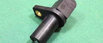
This device is essentially a camshaft controller, which is installed right next to the distributor and ensures its functionality.
On the distributor-interrupter shaft there is a crown-like plate with a certain number of slots, the number of which usually corresponds to the number of cylinders in the engine. The sensor contains a permanent magnet.
When the camshaft begins to move, metal vanes enter the space near the reader. This is how pulse voltage is generated. This voltage moves to the ignition coil, where it becomes higher. The last point of voltage movement is the spark plugs.
The phase sensor on the 8 valve VAZ 2110 has three terminals:
- One is connected to the vehicle ground (“negative” terminal);
- The other is the supply voltage equal to +6 Volts;
- The third is transmitting the pulse to the switch.
Mass air flow sensor (MAF)
It is one of the most important sensors. The mass air flow sensor is responsible for the formation of the air-fuel mixture. It measures the volume of air supplied to the intake receiver and transmits the readings to the electronic engine control unit, which in turn supplies the right amount of fuel in relation to air. The failure of this sensor affects many different functions of the internal combustion engine.
It should be noted that the “CheckEngine” lamp will light up only if the sensor fails completely. Most often, the sensor undergoes aging, but very rarely fails completely. You can read how to check this sensor in our article.
Signs of malfunction:
- Increased fuel consumption;
- Uneven idle speed;
- Difficulty starting the internal combustion engine;
- Loss of dynamics;
- Jerks when moving;
Purpose of DC in the car ignition system
Having understood the principle of operation of the Hall element, let's consider how this sensor is used in the contactless ignition system of the VAZ line of cars. To do this, let's look at Figure 5.
Rice. 5. Principle of the SBZ device
Designations:
- A – sensor.
- B – magnet.
- C – plate made of magnetically conductive material (the number of protrusions corresponds to the number of cylinders).
The operating algorithm of such a scheme is as follows:
- When the chopper-distributor shaft rotates (moving synchronously with the crankshaft), one of the protrusions of the magnetically conductive plate takes a position between the sensor and the magnet.
- As a result of this action, the magnetic field strength changes, which causes the DC to operate. It sends an electrical impulse to the switch that controls the ignition coil.
- The voltage required to form a spark is generated in the Coil.
It would seem nothing complicated, but the spark must appear at a certain moment. If it forms earlier or later, it will cause a malfunction of the engine, even stopping it completely.
Manifestation of malfunction and possible causes
Irregularities in the operation of household farms can be detected by the following indirect signs:
- There is a sharp increase in fuel consumption. This is due to the fact that the fuel-air mixture is injected more than once during one crankshaft rotation cycle.
- Manifestation of unstable engine operation. The car may begin to “twitch” and a sharp deceleration occurs. In some cases, it is not possible to reach a speed of more than 50-60 km/h. The engine stalls during operation.
- Sometimes the failure of the sensor can lead to the transmission being locked, without the ability to shift it (in some models of imported cars). To correct the situation, a restart of the engine is required. In case of regular such cases, one can confidently state that the DP has failed.
- Often, a breakdown can manifest itself in the form of the disappearance of the ignition spark, which, accordingly, will make it impossible to start the engine.
- The self-diagnosis system may experience regular failures, for example, the check engine light will come on when it is idling, and the light will go out when the speed increases.
It is not at all necessary that the listed factors are caused by the failure of the DP. There is a high probability that the malfunction is caused by other reasons, namely:
- ingress of debris or other foreign objects onto the DP housing;
- the signal wire has broken;
- water has entered the DP connector;
- the signal wire is shorted to ground or the on-board network;
- the shielding sheath on the entire harness or individual wires is torn;
- damage to the wires supplying power to the DC;
- the polarity of the voltage supplied to the sensor is reversed;
- problems with the high-voltage circuit of the ignition system;
- problems with the control unit;
- the gap between the DC and the magnetic conductive plate is incorrectly set;
- Perhaps the reason lies in the high amplitude of the end runout of the camshaft gear.
Speed sensor
This sensor is designed to transmit readings to the engine ECU about the speed of the vehicle. It is involved in adjusting the engine speed when driving, namely, if the car is rolling in neutral, you will notice that the speed is slightly higher than the idle speed when the car is standing still. The DS is also responsible for the performance of the speedometer and odometer.
Signs of malfunction:
- Inoperative speedometer or odometer;
- There are no increased speeds when driving in neutral gear;
What is an ignition sensor?
Such a sensor is understood as a control device capable of responding to changes in the magnetic field by modifying the output voltage of the internal combustion engine. Malfunctions of the Hall sensor cause the injector to stop functioning. In its simplest form, the Hall effect ignition sensor, which allows adjacent contacts to be switched, speed sensed, positioned and current commanded, functions as an analogue converter to return power.
Electrical energy in such a device is switched on through a switch (essentially through a conductor). It subsequently emits a magnetic field. Using this device, you can measure the current without interrupting the circuit when the vehicle stalls or a short circuit occurs. It also has a number of important advantages for a car:
- protects the car from dangerous situations on the road, accidents;
- makes it possible to increase engine performance;
- speeds up the functioning of vehicle systems.
As a rule, an ignition sensor using the Hall effect is used in cars to promptly start the internal combustion engine, anti-lock braking system and tachometer.
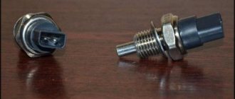
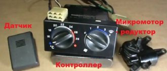
Coolant temperature sensor (DTOZH)
The DTOZH is installed in the thermostat housing and transmits readings to the ECU about the temperature of the engine coolant. Based on these readings, the engine control unit increases or decreases engine speed for more stable operation of the internal combustion engine. The operation of this sensor is noticeable on a cold engine; when starting the engine in the cold season, you can notice increased speed, which decreases over time as the engine warms up to operating temperature.
Signs of malfunction:
- Increased fuel consumption;
- Poor starting on a cold engine;
- Lack of warm-up speeds;
Powertrain heating meter
A device for measuring the coolant temperature of the VAZ-2110 is built into the pipe located on the right side of the engine. The sensor body, which is a thermistor, is in direct contact with the antifreeze. The more the engine and coolant warm up, the more the resistance of this device drops. The controller, which supplies an electrical signal to it, calculates the engine temperature depending on the magnitude of the voltage drop and takes the following actions:
As many as 3 important functions depend on how correctly the VAZ coolant temperature sensor of the tenth family works. The device is considered quite reliable, but sometimes fails due to chafing of the wiring insulation by the accelerator cable, or a break in the circuit inside the element, which happens less frequently. Damaged wires must be replaced, as well as the faulty device itself.
Several recommendations on how to check the temperature sensor. The following signs indicate a malfunction:
- a noticeable increase in fuel consumption because the processor does not prepare the mixture correctly due to a non-functioning meter;
- an engine warmed up to operating temperature does not start well;
- the fan turns on spontaneously at different temperatures;
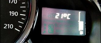
- a non-working coolant sensor causes incorrect readings on the panel.
It is not difficult to replace an element; access to it is open. But when unscrewing, antifreeze will flow from the pipe, so you must first wait until the power unit cools down. Then take a plastic container and partially empty the cooling system by draining the antifreeze from the cylinder block. After this, you can unscrew the old one and install a new VAZ-2110 temperature sensor.
Crankshaft position sensor (CPS)
DPKV is a sensor that counts crankshaft revolutions. Just like most sensors, it participates in the formation of the fuel mixture. If it malfunctions, the car will not start.
The sensor is installed on the rear of the engine under the oil filter. Works in tandem with the crankshaft pulley (generator drive).
Signs of malfunction:
- The car does not start (no spark);
- Jerks when moving;
- Spontaneous engine stop;
Phase sensor (PF)
This sensor is necessary for counting camshaft revolutions; its functions are similar to those of the DPKV. Designed for phased fuel injection; without this sensor, the internal combustion engine will operate in emergency mode and the fuel supply will switch to pairwise mode.
It is installed under the timing cover on 16-valve engines, and on 8-valve engines on the end of the cylinder head on top of the thermostat.
Signs of malfunction:
- Increased fuel consumption;
- Unstable work at XX;
- Loss of dynamics;
Objectives and principle of operation
Today, the hall sensor on the VAZ 2110 plays a vital role, being an integral part of the car’s ignition system. If this unit fails, the engine will start to work incorrectly or stop working completely.
On the distributor-interrupter shaft there is a crown-like plate with a certain number of slots, the number of which usually corresponds to the number of cylinders in the engine. The sensor contains a permanent magnet.
When the camshaft begins to move, metal vanes enter the space near the reader. This is how pulse voltage is generated. This voltage moves to the ignition coil, where it becomes higher. The last point of voltage movement is the spark plugs.
The phase sensor on the 8 valve VAZ 2110 has three terminals:
- One is connected to the vehicle ground (“negative” terminal);
- The other is the supply voltage equal to +6 Volts;
- The third is transmitting the pulse to the switch.
Idle air control (IAC)
This sensor is installed on the throttle valve and regulates the air supply when the car is running at idle. In other operating modes of the internal combustion engine, the idle air regulator is not involved. The sensor performs mechanical functions, so if it malfunctions, the “CheckEngine” warning light does not light up.
If the regulator breaks down, you can wash it and try installing it again. If washing does not help, the sensor must be replaced with a new one.
Signs of malfunction:
- Unstable idle;
- The engine stalls when coasting;
- Difficulty starting the engine;
- Low speed XX;
Verification methods
To check the serviceability of the Hall device on the VAZ 2110 injector, the following methods exist:
- The easiest way is to find a working device (ask a motorist you know who has a car with an injector) and put it in place of the one being tested. If the problems disappear, then the cause of the breakdown is in the device.
- The voltage at the output of the device is measured using a tester. The lower limit is 0.4 V, the upper limit is 11 V.
- Create a simulation of the operation of a Hall device on a machine with an injector. To do this, remove the block from the distributor, which has three plugs. Then turn on the ignition and connect the 3rd and 6th outputs on the switch with a wire. If a spark jumps, the device is faulty.
- The check can be done using the spark plug. It must be connected to the ignition coil terminal. The threaded connection must be connected to ground. Next, you should remove the block with the meter and attach the connector. After turning on the ignition, a metal object, such as a screwdriver, must be held in the immediate vicinity of the device being tested. If a spark appears on the spark plug, then the device is in working condition. Checking the Hall sensor
Throttle Position Sensor (TPS)
TPS is designed to transmit indications about the position of the valve in the throttle assembly. The received readings are transmitted to the ECU for further regulation of the fuel mixture. This sensor fails quite often. Located on the throttle valve above the IAC.
The sensor cannot be repaired and if it breaks, it is replaced with a new one.
Signs of malfunction:
- Spontaneous increase and decrease in speed;
- Difficulty starting the engine;
- Increased fuel consumption;
- Low speed XX;
Oil pressure sensor (OP)
This sensor signals the condition of the oil pressure in the engine. When it decreases, a lamp on the car’s dashboard lights up in the form of a red oil can. The sensor is completely mechanical and is only responsible for turning on the low oil pressure indicator.
Signs of malfunction:
- The oil pressure lamp does not light up;
- The oil pressure lamp is constantly on;
Example of using an analog element
Let us consider, as an example, the design of a current sensor whose operation is based on the Hall effect.
Simplified circuit of a current sensor based on the Hall effect
Designations:
- A is a conductor.
- B – open magnetic conductor ring.
- C – analog Hall sensor.
- D – signal amplifier.
The operating principle of such a device is quite simple: the current passing through the conductor creates an electromagnetic field, the sensor measures its magnitude and polarity and produces a proportional voltage UDT, which is supplied to the amplifier and then to the indicator. https://www.youtube.com/watch?v=fmLs9WsKx3I
Oxygen sensor (OS)
The VAZ 2110 oxygen sensor is installed in the exhaust manifold. The DC measures the exhaust gases and uses their readings to determine the ratio in which the fuel mixture is formed. If the readings exceed the permissible values, the ECU adjusts the air-fuel mixture in such an amount that the exhaust gases do not exceed the permissible values.
Signs of malfunction:
- Increased fuel consumption;
- Loss of vehicle dynamics;
- Black smoke when driving at high speeds;
Camshaft sensor on VAZ 2110: do-it-yourself replacement
Many of you probably remember from school about such a concept as the Hall effect . If you forgot, then it reminds you. If electricity constantly flows in a conductor, and this conductor is placed in a magnetic field, a potential difference will appear.
This principle forms the basis for the functioning of the hall sensor, which is used, among other things, on the VAZ 2110 car.