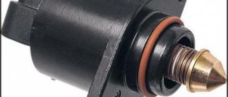
Idle speed regulator (sensor) VAZ 2107
In everyday life, the IAC is called a sensor, although it is not one. The fact is that sensors belong to measuring equipment, and regulators belong to executive equipment. In other words, it does not collect information, but executes commands.
Purpose
The IAC is a component of the fuel supply system of an engine with distributed injection, regulating the volume of air entering the intake manifold (receiver) when the throttle valve is closed. In fact, this is an ordinary valve that slightly opens the spare (bypass) air channel by a given amount.
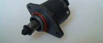
IAC device
The idle speed control is an electric motor of a stepper design, consisting of a stator with two windings, a magnetic rotor and a rod with a spring-loaded valve (shut-off tip). When voltage is applied to the first winding, the rotor rotates to a certain angle. When it is fed to another winding, it repeats its movement. Due to the fact that the rod has a thread on its surface, when the rotor rotates, it moves back and forth. During one full revolution of the rotor, the rod takes several “steps”, moving the tip.
1 - valve; 2 — regulator body; 3 - stator winding; 4 — lead screw; 5 — plug terminal of the stator winding; 6 — ball bearing; 7 — stator winding housing; 8 - rotor; 9 - spring
Operating principle
The operation of the device is controlled by an electronic unit (controller). When the ignition is turned off, the IAC rod is pushed forward as much as possible, which is why the passage hole of the bypass channel is completely blocked, and air does not enter the receiver at all.
When the power unit starts, the electronic controller, based on data received from temperature and crankshaft speed sensors, supplies a certain voltage to the regulator, which, in turn, slightly opens the flow area of the bypass channel. As the power unit heats up and its speed decreases, the electronic unit through the IAC reduces the flow of air into the manifold, stabilizing the operation of the power unit at idle.
The operation of the regulator is controlled by an electronic control unit
When we press the accelerator pedal, air enters the receiver through the main channel of the throttle assembly. The bypass channel is blocked. To correctly determine the number of “steps” of the device’s electric motor, the electronic unit additionally uses information coming from the throttle position, air flow, crankshaft position and speed sensors.
When additional load occurs on the engine (turning on the radiator fans, heater, air conditioner, heated rear window), the controller, through the regulator, opens a spare air channel to maintain the power of the power unit, preventing dips and jerks.
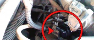
Where is the idle air control on a VAZ 2107?
The IAC is located in the throttle body. The assembly itself is attached to the rear of the engine intake manifold. You can determine the location of the regulator by the wiring harness that fits its connector.
The IAC is located in the throttle body
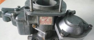
Idle speed control in carburetor engines
In carburetor power units of the VAZ 2107, idle speed is ensured using an economizer, the actuator of which is an electromagnetic valve. The valve is installed in the carburetor body and is controlled by a special electronic unit. The latter receives data on the number of engine revolutions from the ignition coil, as well as on the position of the throttle valve of the primary chamber of the carburetor from the contacts of the fuel quantity screw. Having processed them, the unit supplies voltage to the valve, or turns it off. The design of the solenoid valve is based on an electromagnet with a shut-off needle, which opens (closes) the hole in the idle fuel jet.
Setting the float chamber level
This is the first step in adjusting any carburetor. It is on this part that the consumption and stability of the engine will depend. The level must be at the nominal level set by the manufacturer, so it is very important to follow the technology.
Setting the fuel level in the float chamber: I - carburetor cover; 2 — needle valve seat; 3 - emphasis; 4 - needle valve; 5 - locking needle ball; 6 - valve needle pull-out fork; 7 — float bracket; 8 - tongue; 9 — float; 10 - gasket.
The top cover of the carburetor is removed, but before that, you need to pump up the manual fuel pump to check the set level. The nominal level is the level of gasoline located on half of the inclined surface. If it is higher or lower, then adjust the float level by bending the adjusting antennae. The XX speed is also regulated by the float chamber.
To check, just put the cover on top, start the engine and immediately turn it off. Open the lid again and check the level. After this, you can move on to the next stage.
Signs of IAC malfunction
Signs that the idle air control valve is faulty may include:
- unstable idling (the engine troits, stalls when the accelerator pedal is released);
- decreasing or increasing the number of engine revolutions at idle (floating speed);
- reduction in the power characteristics of the power unit, especially with additional load (turning on the heater fans, radiator fans, heated rear window, high beam, etc.);
- complicated engine starting (the engine starts only when you press the gas pedal).
But here it should be borne in mind that similar symptoms may also be inherent in malfunctions of other sensors, for example, throttle position sensors, mass air flow or crankshaft position sensors. In addition, if the IAC malfunctions, the “CHECK ENGINE” indicator lamp on the dashboard does not light up, and it will not be possible to read the engine error code. There is only one way out - a thorough check of the device.
Why does it start and stall?
If you turn on the logic, there may be several main reasons why the engine stalled after starting:
- insufficient amount of fuel;
- exhaust system malfunctions;
- failures in the formation of the air-fuel mixture and its supply to the injectors.
It can be assumed that the cause is faulty spark plugs or a clogged air filter. But spark plugs do not all fail at once. If one spark plug does not work, the engine starts to stall, but this will not cause it to stall. To clog the filter to such an extent that it is unable to pass air through itself requires a lot of effort. When there is no air supply, the engine will not start at all, and even if it does start, the thrust will drop significantly. Traveling would be difficult, if not impossible.
Exhaust system malfunctions
Everything is simple here: if you close the pipe tightly, the engine will stall after some time. Even if you start it again, it will run for a few seconds and then die again. This happens because the exhaust gases have nowhere to go: they cannot get out, and fall through the exhaust manifold back into the combustion chambers. There, the gases mix with the air-fuel mixture, ignition becomes impossible, and the engine stalls.
Exhaust gases are not removed for several reasons:
- catalyst malfunction (can also be heavily contaminated);
- water in the muffler.
The situation with a clogged catalyst is rare. To do this, the water in it needs to freeze, but this is unlikely.
But water in the muffler happens quite often. It freezes in winter and exhaust gases cannot escape. There are few reasons why water gets in. Basically, this is a broken cylinder head, which causes antifreeze to enter the exhaust system and, mixing with condensate, freezes. Although, if the cylinder head gasket is punctured, the problem of ice in the muffler will seem like a trifle, since more serious repairs await.
Incorrect fuel/air mixture
Such situations occur frequently. In this case, the engine either does not start at all, or runs erratically. There are few reasons, these are:
- incorrect operation of the throttle assembly;
- air intake in addition to the air duct in front of the air filter (suction).
The throttle valve is directly involved in the formation of the fuel mixture, and disruption of its functioning leads to malfunctions of the power plant. The air leak makes the mixture too lean, and the engine cannot work on it, which is why it stalls. To eliminate these problems, you need to clean the throttle assembly (or replace it if it is faulty) and look for the location of the air leak.
Insufficient fuel supply
The symptom is simple: after starting, the engine runs for 5–10 seconds and stalls. In most cases, the cause is the fuel pump located in the fuel tank. To be precise, the problem is a clogged fine filter or mesh. This detail, insignificant at first glance, does not allow dirt particles to enter the fuel line, which, like water in the gas tank, is abundant (especially on cars with a mileage of 50,000 or more).
In summer, the water and other substances in the tank are liquid and can pass into the main line, but in winter they often turn into ice on the mesh filter. This causes the fuel pump to be unable to pump enough fuel to run the engine. Therefore, it turns out that the pump manages to pump a little fuel, and this is just enough to start the engine, but no more. To eliminate this problem, it is enough to replace or clean the fuel pump mesh.
Checking the idle air control circuit
Before moving on to diagnosing the regulator itself, it is necessary to check its circuit, because the reason that it stopped working could be a simple break in the wires or a malfunction of the electronic control unit. To diagnose the circuit, you only need a multimeter with the ability to measure voltage. The procedure is as follows:
- Raise the hood and find the sensor wiring harness on the throttle assembly.
- Disconnect the wiring harness block.
Each of the IAC pins is marked - Turn on the ignition.
- We turn the multimeter into voltmeter mode with a measurement range of 0–20 V.
- We connect the negative probe of the device to the ground of the car, and the positive one in turn to terminals “A” and “D” on the wiring harness block.
The voltage between ground and terminals A, D should be approximately 12 V
The voltage between ground and each of the terminals must correspond to the voltage of the on-board network, i.e. approximately 12 V. If it is less than this indicator, or is absent at all, you need to diagnose the wiring and electronic control unit.
Testing the mass air flow sensor (MAF)
Let us remind you what we are talking about - VAZ-2110 8-valve injector: the speed drops and stalls. A reasonable question arises: what to do? If the reason is not the IAC, then it is worth testing the mass air flow sensor. Here are some recommendations on how to do this:
- Disconnect the sensor connector from the on-board system. The controller that controls the engine will operate in emergency mode, but for short testing this is not fatal. If your car runs much faster, then the problem is most likely in the mass air flow sensor. It's time to clean it.
- Replace the sensor with a working one, and then see how the engine works. There are improvements, which means you need to either clean or replace your own mass air flow sensor.
- It also makes sense to inspect the air intake; to do this, you need to remove the mounting clamp and carefully inspect the inside of the air intake, there should be no condensation or oil there. If any are found, then it will have to be cleaned with special means.
- You can also test the mass air flow sensor using a multimeter. To do this, you need to switch the multimeter to voltmeter mode and set it to 2. The sensor has 2 wires - yellow and green. Yellow transmits a signal to the controller, and green transmits a signal to ground. When the ignition is turned on, we take measurements between these two wires. The engine should not be running. If the readings are in the range of 1.01-1.02, then the sensor is in perfect order. Readings in the range of 1.02-1.03 – it’s time to clean the sensor. And if the indicators go off scale to 1.04, then it’s time to get a new sensor.
We recommend: Arranging the exterior of your car
Diagnostics, repair and replacement of idle air control
To check and replace the regulator itself, you will need to dismantle the throttle assembly and disconnect the device from it. The following tools and resources will be needed:
- screwdriver with Phillips bit;
- slotted screwdriver;
- round nose pliers;
- socket wrench or socket 13;
- multimeter with the ability to measure resistance;
- calipers (you can use a ruler);
- clean dry cloth;
- coolant for topping up (maximum 500 ml).
Dismantling the throttle assembly and removing the IAC
To remove the throttle assembly, you must:
- Raise the hood and disconnect the negative cable from the battery.
- Using a slotted screwdriver, hook the end of the throttle cable and remove it from the gas pedal pin.
- On the throttle block, use round pliers to disconnect the clamp on the throttle valve drive sector.
The fastener is detached using pliers or a screwdriver - Turn the sector counterclockwise and disconnect the cable end from it.
To disconnect the tip, you need to turn the drive sector counterclockwise - Remove the plastic cap from the cable end.
- Using two 13mm wrenches, loosen the cable fastening on the bracket.
To loosen the cable, you need to loosen both nuts - Pull the cable out of the bracket slot.
To remove the cable, it must be removed from the bracket slot - Disconnect the wire connectors from the IAC connectors and the throttle position sensor.
- Using a screwdriver with a cross-shaped bit or pliers (depending on the type of clamps), loosen the clamps on the coolant inlet and outlet fittings.
Remove the clamps. In this case, a small amount of liquid may leak out. Wipe off any spills with a dry, clean cloth. The clamps can be loosened with a screwdriver or pliers (round pliers) - In the same way, loosen the clamp and remove the hose from the crankcase ventilation fitting.
The crankcase ventilation fitting is located between the coolant inlet and outlet fittings - Using a Phillips-head screwdriver, loosen the clamp on the air supply pipe.
Remove the pipe from the throttle body. The air pipe is fixed with a worm clamp - Similarly, loosen the clamp and remove the hose for removing fuel vapors from the fitting on the throttle assembly.
To remove the fuel vapor exhaust hose, you need to loosen the clamp - Using a socket wrench or a 13mm socket, unscrew the nuts (2 pcs) securing the throttle assembly to the intake manifold.
The throttle assembly is attached to the manifold using two studs with nuts - Remove the throttle body along with the sealing gasket from the manifold studs.
A sealing gasket is installed between the throttle assembly and the manifold - Remove the plastic bushing that defines the air flow configuration from the manifold.
The plastic sleeve sets the air flow configuration inside the manifold - Using a Phillips-head screwdriver, remove the two screws securing the regulator to the throttle body.
The regulator is attached to the throttle body with two screws - Carefully remove the regulator, being careful not to damage the rubber O-ring.
A rubber sealing ring is installed at the junction of the IAC with the throttle assembly
Video: removing and cleaning the throttle assembly on a VAZ 2107
Step-by-step replacement procedure
The replacement procedure is carried out in almost the same way as cleaning the device, but there are certain nuances:
- The battery is disconnected to prevent a short in the wiring.
- The plug with the electrical circuit is disconnected from the control device. If the car is equipped with an injection power unit, then to disconnect the connector you need to press on the plastic fastener.
- The bolts are unscrewed. As when cleaning, first unscrew the left fastener, and then the right one. The failed regulatory device is being dismantled.
- The surface on which the sealing element is mounted is also cleaned. The latter is checked for defects - abrasions, cracks, etc. If they are present, the sealing gum is replaced with a new one. Before installation, the seal is treated with engine fluid, after which it is mounted on the throttle seat.
- The controller is installed, a connector with wires for its power supply is connected. A wire is connected to the battery.
- After installation, a calibration procedure is performed. The microprocessor module must perform this independently; an electronic relay is used for this. To calibrate the new sensor, the ignition is turned on for a few minutes and then turned off. If the actions performed helped and the speed no longer floats, but remains at the same level, then the replacement procedure can be considered complete.
What do you need to know when replacing the IAC?
To change and install a controller that allows you to regulate idle speed, you need to pay attention to the position of the rod. It must not be allowed to be pushed forward too much. This can happen if the device is connected to the block and the ignition is activated before installation. It is not allowed to push the rod in by hand.
If the valve is installed with the needle extended and the retaining screws are tightened, damage to the unit may occur due to shearing of the worm gear. It is impossible to repair such a sensor. Depending on the vehicle model, after installing a new regulator, it may need to be calibrated. In some cars, this procedure is carried out using special equipment or a stand.
On VAZ cars, calibration is performed as follows:
- A terminal is connected to the negative output of the battery.
- The key is turned in the lock to turn on the ignition for ten seconds. There is no need to start the power unit.
- The ignition is turned off.
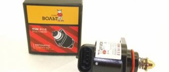
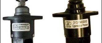
Learning to distinguish a fake from an original
Today, many people complain about the abundance of counterfeit products on the auto parts market.
If we talk specifically about the XX regulator for the VAZ 2110, then there are several key signs by which a fake can be distinguished from the original. Be guided by these data so as not to accidentally install a device of dubious quality and origin on your car.
Fake and original
- On fakes, the black body made of metal is 1 millimeter shorter than the real part.
- In the case of the fake, the three white rivets on the case have no heads. They must be present in the original. And the diameter of the caps is 3 millimeters.
- On fakes, the spring is made in white and has more frequent winding. In the original, the coiling is less frequent, and the spring itself is black.
- Pay attention to the rubber ring of the regulator. On fakes it is black and thin, but in the case of a real part, a reddish tint is noticeable. Plus the thickness is greater.
- Take a closer look at the tip. In fakes it is darker compared to the original spare part.
- There are no markings on the counterfeit packaging; the boxes are noticeably different in appearance.
- The original yellow sticker located on the case must have an outer frame. Manufacturers of counterfeits apparently forgot about it.
As you can see, recognizing a fake is not difficult. You just need to be more attentive to details.
The difference is in the boxes
How to check the idle air control
To check the IAC, perform the following steps:
- Turn the multimeter into ohmmeter mode with a measurement limit of 0–200 Ohm.
- Connect the probes of the device to terminals A and B of the regulator.
Measure the resistance. Repeat the measurements for terminals C and D. For a working regulator, the resistance between the indicated terminals should be 50–53 Ohms. The resistance between adjacent paired terminals should be 50–53 Ohms - Switch the device to resistance measurement mode with the maximum limit. Measure the resistance between contacts A and C, and after B and D. The resistance in both cases should tend to infinity.
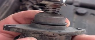
- Using a caliper, measure the extension of the regulator locking rod in relation to the mounting plane. It should be no more than 23 mm. If it is greater than this indicator, adjust the position of the rod. To do this, connect one wire (from the positive terminal of the battery) to terminal D, and briefly connect the other (from ground) to contact C, simulating a pulsed voltage supply from the electronic control unit. When the rod reaches its maximum reach, repeat the measurements.
If the resistance value between the listed terminals does not correspond to the specified values, or the stem overhang is more than 23 mm, the idle air control regulator must be replaced. There is no point in trying to repair the device. In the event of a break or short circuit in the stator windings, and it is these faults that cause changes in the resistance at the terminals, the regulator cannot be restored.
The rod should be extended 23 mm
Cleaning the idle air control
If the resistance is normal and the length of the rod is fine, but it does not move after connecting the voltage, you can try to clean the device. The problem may be that the worm mechanism that moves the rod is jammed. For cleaning, you can use a rust-fighting liquid such as WD-40 or its equivalent.
The liquid is applied to the rod itself where it enters the regulator body. But don’t overdo it: you don’t need to pour the product inside the device. After half an hour, grab the rod and gently twist it from side to side. After this, check its functionality by connecting the wires from the battery to terminals D and C, as described above. If the regulator rod begins to move, the device can be used again.
Preventive measures
In order not to encounter a complete malfunction of the regulator in the future, it is worth periodically carrying out the cleaning process described above. How often to carry out the cleaning process depends on how actively you use your vehicle. If the car is a work vehicle, it is recommended to check and clean the sensor once a year; if you use it only for yourself, once every two years will be enough. But, of course, do not forget about the signs of a part malfunction; if they appear, do not delay. This will help you avoid complete failure of the part and enjoy a high-quality ride. Together with you, we come to the conclusion that the part is unpretentious, simple in its functionality and use. Don’t forget: timely detection of a malfunction is the key to overall vehicle productivity. The full operation of the engine depends on the serviceability of each of its components, and if you neglect any part, including the idle speed sensor, this can lead to more labor-intensive repair processes and failure of the entire car.
Checking the idle speed sensor
Diagnosing the part is quite easy, but pay attention to a few points. The first problem may be removing the part; most manufacturers attach the XX sensor to screws, and in extreme cases they can be drilled out, but in some variations the part is mounted on varnish
If your regulator is secured with varnish, be careful not to forcefully remove it, as this may damage the intake part of the car. In your case, it would be correct to completely dismantle the throttle assembly and only then disconnect the IAC.
The easiest way to check is, of course, visual inspection.
During a visual inspection, the first thing you should pay attention to is whether the needle is dirty. Also pay attention to the condition of the contacts and the throttle valve itself.
If broken wires are found, they must be returned to their place. Solder them and, to avoid corrosion, treat them with varnish.
It would be appropriate, if possible, to check the IAC with a multimeter or a homemade tester. You can check the resistance with a multimeter, and use a homemade tester (you can make one from a mobile phone charger) to check the stroke of the regulator rod.
If you find that the motor is damaged, the rod is completely worn out, or the cone needle is worn out, the part will need to be replaced. Don’t be too upset about this, the cost of the part will only be about 1000 rubles.
What is better to buy
If the IAC check indicates the need for purchase, then you should select a part that is suitable for the series. For example, "OMEGA" No. 2112-114830; "KZTA" No. 2112-1148300-04. The last two digits (04) have special meaning. If the previous sensor ended in number 01, and instead of it you put, say, 03, then it will be a waste of time and money: it will not work. Therefore, it makes sense to change the sensor either to the same one, that is, with the same number, or to an interchangeable one: 01 can be changed to 02, and 03 will replace 04.
Attention: buying a new regulator will not be difficult, and it is not that expensive, 300-350 rubles. However, in the modern market they often sell low-quality parts and fakes. So be careful and buy the product from trusted auto parts stores.