Hello everybody! I propose to discuss with me how to check the diode bridge of the generator. The topic is quite relevant, since it is not so rare for motorists to encounter generator malfunctions.
The diode bridge (DM) plays a big role in the performance of all electrical equipment in the vehicle. The key feature of DM is the ability to rectify current.
There are situations when the bridge cannot cope with its assigned tasks and signs of malfunctions appear. But how can you tell if there are problems with it without removing the generator? This is exactly what we will talk about today.
Signs of diode failure
The main problem in a rectifier bridge is the diodes. You should start checking the unit that generates electricity in the car only after identifying the following indirect problems:
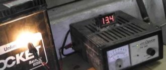
- the voltage at the generator output terminals is below 13.5 Volts;
- the indicator on the instrument panel inside the car continues to light after starting the power unit;
- the arrow on the voltmeter shifts to the red zone when readings are taken;
- The battery indicator does not light up after turning on the ignition.
Similar symptoms are detected when the voltage regulator breaks down; therefore, its serviceability is checked first. There are various reasons why a rectifier bridge fails, which requires its repair or complete replacement.
Nuances of moving a generator
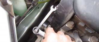
The disadvantage of domestic Niva SUVs is the location of the generator unit - at the bottom of the engine compartment. It constantly gets contaminated when driving off-road, and coolant constantly drips. The problem is solved by moving the generator upstairs (the author of the video is SARTANETS).
To transfer, you will need a set of keys, a bracket, mounting bolts, and a V-belt. You can make a generator transfer bracket with your own hands according to the drawing below.
Drawing of a homemade bracket
Sequence of actions during transfer:
- We dismantle the propeller, pump and remove the belt.
- By unscrewing the standard bracket, you can remove the generator.
- We cut off the bead around the side of the cylinder head and on the cylinder block.
- Then you should unscrew the two bolts and two studs.
- Next, the assembly is installed on a new bracket and final assembly is performed.
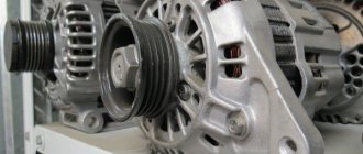
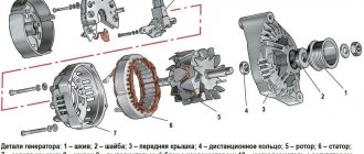
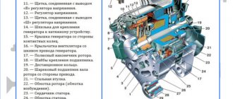
Generator design: its composition
ATTENTION! A completely simple way to reduce fuel consumption has been found! Don't believe me? An auto mechanic with 15 years of experience also didn’t believe it until he tried it. And now he saves 35,000 rubles a year on gasoline! Read more". The mere fact that a gene is always under high load a priori includes it in the risk group
He needs an eye and an eye. Experienced and caring motorists know this. Beginners and amateurs don’t pay attention, “ruin” the new device and battery, and then wonder why the car doesn’t drive.
The mere fact that a gene is always under high load a priori includes it in the risk group. He needs an eye and an eye. Experienced and caring motorists know this. Beginners and amateurs don’t pay attention, “ruin” the new device and battery, and then wonder why the car doesn’t drive.
What does a gene consist of? Its components necessarily include a rotor or inductor. Its main function is to create a magnetic field inside the device. The rotor has a shaft on which there is an excitation winding. Due to it, the gene is recharged or self-excited.
Rectifier design
In the literal sense, a rectifier is not able to “straighten” alternating voltage. This unit received its name because of the operating principle of the diodes included in it:
Currently, high-power diodes have a classic design; low-power semiconductor devices of this type are made in the form of a silicon junction on a board. However, to remove high temperatures from the body or silicon junction, both modifications are either embedded in the heat sink plate or equipped with their own individual radiators.
If a silicon junction or a full-fledged diode in the housing breaks down, the diode bridge of the generator or individual semiconductors included in its composition must be replaced.
Main diode bridge
The lower figure shows sinusoids and the direction of current movement in the generator and diode bridge.
The positive value is conditionally taken to be the voltage directed to the 0 point of the stator winding. After the rectifier, the current in the consumer load flows only in the positive direction, that is, from the “+” of the generator to its mass “-”.
Therefore, the power diode bridge (main) uses large-sized 25 - 30 A diodes, the power of which can be further increased due to the additional rectifier arm discussed below.
Unlike other components of the “auto power plant”, a visual inspection does not allow us to identify any faults in the diode bridge of the generator. The rectifier requires only hardware diagnostics with a multimeter.
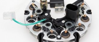
The diodes are located on a horseshoe-shaped heat sink plate under the back cover of the generator. On remote rectifiers, the diode bridge is located near the generator; instead of plates of the classical configuration, a regular board can be used. In this case, a finned radiator is placed on the body of each diode.
Additional diodes
The main difficulty in the design of a car generator is that the excitation winding of its armature is also a consumer of constant voltage. This coil uses the generator's own diode bridge:
Instead of powerful semiconductor devices, small-sized 2 A diodes are used.
Zener diode
Since the amount of voltage generated by the machine’s generator directly depends on the speed of the crankshaft, which transmits torque to its pulley, “spikes” of up to 20 V are possible in the on-board network, which is harmful for consumers. To eliminate frequent repairs, the easiest way is to connect the rectifier diode bridge via a zener diode:
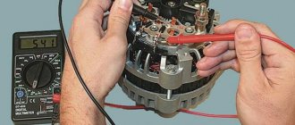
When diagnosing a rectifier, checking the diode bridge of the generator with a multimeter is carried out indirectly:
The check is described in more detail in the following paragraphs of this manual.
Additional rectifier arm
Phase voltages are characterized by a deviation of the voltage graph from a sinusoid. Therefore, a generator circuit with an additional rectifier arm is only possible when the stator windings are connected in a star:
The magnitude of the shoulder is 5–15% of the generator power, but it occurs only at speeds above 3000 rpm. The durability of the rectifier also depends on the performance of the voltage regulator. But repairs are available to the owner of the car after disassembling the generator.
How is the check carried out?
To check a semiconductor using a tester, you need to make sure that the multimeter has a diode test mode. After this, the work algorithm will be as follows:
- the red probe is inserted into the socket marked “VΩmA”;
- black – to the “COM” connector;
- select the mode for measuring resistance;
- the end of the red probe is connected to the anode, and the black one to the cathode;
- readings of changes in direct resistance are taken.
After all the operations performed, we can draw a conclusion about the performance of the semiconductor.
Checking the diode bridge
In a number of situations, it is necessary to check the condition of the diode bridge. It is a system of 4 diodes connected in such a way that the alternating voltage supplied to the two soldered components is converted to direct voltage.
The measurement algorithm is very similar to the classic method for testing a diode. However, there are also some nuances, namely the presence of 4 connection options depending on the pin number. The following combinations are usually called:
Analysis of results
Having received the test result, we can conclude that the semiconductor is serviceable. Signs of diode performance are:
- Coincidence of the forward voltage value displayed on the display when the element is connected to the tester with the indicators for a given type of diode.
- The zero value produced by the multimeter when connected in reverse.
If these parameters are observed, one can judge the working condition of the diode and the presence of a breakdown elsewhere. If one of the indicators does not meet the requirements, the semiconductor is considered non-working and must be replaced.
Checking diodes for serviceability using a tester is not so difficult on your own. A large assortment of multimeters on the market will allow you to choose a completely budget model, which will allow you to assess the performance of the diode in the circuit of any household electrical appliance.
How to test a diode with a multimeter without unsoldering it
Checking the Schottky diode is carried out without unsoldering it from the circuit, since this type of semiconductor is placed in a double case with a common cathode. So the measurement in this case can be done “on the spot”.
Read also: Pipe designation in inches
The same difficulties can arise when checking an LED. In some cases, it is necessary to evaluate a semiconductor without soldering it. Standard multimeter probes are not suitable for this, so you will have to make a special device that allows you to reach the electrodes in the circuit.
All work will include the following operations:
- On each side of a small foil fragment of PCB it is necessary to apply a small amount of solder on which the wires will be fixed.
- Straighten paper clips or small pieces of steel wire, which will then be soldered to the textolite gasket. Secure the entire structure with electrical tape.
- Prepare a multimeter with transistor testing mode.
- Connect the designed adapter to the tester.
- Place the probes on the legs of the semiconductor located in the circuit.
- To inspect.
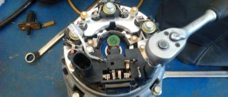
How is the replacement performed?
Let's say checking the diode bridge shows that there is a problem. It is necessary to disconnect all wires from the generator, remove and disassemble the device. In some models, the part is attached directly to the unit with bolts, but there are devices in which the housing must be removed to access the rectifier.
Next, as part of the repair, faulty diodes are replaced - if this is economically feasible and it is difficult to find the required generator model on sale. Or they change the component entirely. Upon completion of work on the stand, the serviceability of the component and the electrical system as a whole is checked using a multimeter, and the part is assembled and installed on the car.
You can check the diode bridge yourself if you have the time and skills to disassemble the generator. But even after checking and detecting faulty diodes, you will need to select and correctly install a new element instead of the faulty one. Remember that a faulty generator can cause failure of expensive electrical equipment, short circuits and spontaneous combustion of the car. Therefore, it is better to trust repairs and diagnostics to car service technicians, who will definitely be able to call you correctly!
Testing the diode bridge with a multimeter
Any part on the board can be desoldered for testing or ringing without desoldering. However, the accuracy of the check in this case is reduced, because perhaps a lack of contact with the board tracks, with visible “normal” soldering, the influence of other circuit elements. This also applies to the diode bridge; you don’t have to desolder it, but it’s better and more convenient to desolder it for testing. A bridge assembled from individual diodes is quite convenient to check on the board.
Almost every modern multimeter has a diode test mode, usually it is combined with an audio continuity test of the circuit.
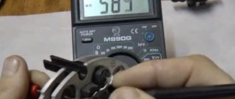
This mode displays the voltage drop in millivolts between the probes. If the red probe is connected to the anode of the diode and the black probe to the cathode, this connection is called forward or conductive. In this case, the voltage drop across the PN junction of the silicon diode is in the range of 500-750 mV, which you can see in the picture. By the way, it shows a test in resistance measurement mode, this is also possible, but there is also a special diode test mode, the results will be, in principle, similar.
Read also: Construction clamps for scaffolding
If you swap the probes - red to the cathode, and black to the anode, the screen will show either one or a value of more than 1000 (about 1500). Such measurements indicate that the diode is working; if the measurements differ in one of the directions, then the diode is faulty. For example, if the continuity test is triggered - the diode is broken, there are high values in both directions (as with reverse switching on) - the diode is broken.
Important! Schottky diodes have a lower voltage drop, about 300 mV. There is also an express check of the diode bridge with a multimeter
The procedure is as follows:
There is also an express check of the diode bridge with a multimeter. The procedure is as follows:
- We place probes at the input of the diode bridge (
or AC), if the bell is triggered, it is broken.
We put the red probe on “–”, and the red one on “+” - a value of about 1000 appears on the screen, swap the probes - on the screen 1 or 0L, or another high value - the diode bridge is working
The logic of this test is that the diodes are connected in series in two branches, pay attention to the diagram, and they conduct current. If the positive power supply is applied to – (anode connection point), and the power supply minus is applied to “+” (cathode connection point), this is what happens when dialing
If one of the diodes is broken, current may flow through the other branch and you may make erroneous measurements. But if one of the diodes is broken, the voltage drop across one diode will be displayed on the screen.
Do-it-yourself washing of a car catalyst: choosing a product
- the bridge is dismantled from the generator (no other way);
- each diode will need to be checked separately;
- the beeper mode is selected on the measuring device;
- This setting will allow you to hear a signal when the probe is shorted;
- if this mode is not available, select the 1kOhm position;
- the probes are brought to the edges of the diode;
- a measurement is made;
- the probes are swapped.
Now regarding the measurement results. Everything is fine with the diode, if in one position you see an infinity sign on the screen, in the second it gives a value in the range from 500 to 700 Ohms.
If the device shows a lower resistance value, or there is an infinity sign in two positions, you have found a faulty diode.
Bulb
Now let's see how the procedure is carried out using a regular light bulb. This is a good alternative for those cases when you don’t have a multimeter.
The most ordinary 12 V lamp will do the job.
What you need to know about diode bridges
First, we will look at what they are and what is inside a diode bridge. These circuit elements are available in two versions:
- From discrete (separate) diodes. Usually soldered on the board and connected by tracks in the correct circuit.
- Diode assemblies. The assemblies can be either single-phase bridges for rectifying both half-cycles of alternating voltage, or assemblies of two diodes connected in a circuit by a common cathode or anode, and other connection options.
In any case, the rectifier single-phase diode bridge consists of four semiconductor diodes connected to each other in a series-parallel manner. Alternating voltage is supplied to two points at which the anode and cathode are connected (opposite poles of the diodes). Constant voltage is removed from the connection points of like poles: plus from the cathodes, minus from the anodes.
In the diagram, the location of the AC voltage connection is indicated by the symbols AC or “
", and the outputs with constant voltage are "+" and "-". Draw this diagram for yourself, it will be useful to us when checking.
If you imagine a real diode bridge and combine it with this circuit, you get something like:
Principle of operation
The operation of a diode semiconductor bridge that conducts current is simple. The principle of operation is based on the property that a semiconductor diode passes electric current in one direction and does not pass in the other. So, if the charges are connected correctly, current will flow through the device.
The difference between alternating current and direct current is that it can only move in one direction. Moreover, do this in one half-cycle. During the other half of the period, it can make the opposite movement. When several diodes are connected in a circuit, they will begin to move, creating a direct current.
It is easy to assemble a diode bridge circuit. Anyone can do this. It includes four diodes, which are connected to each other by a square. Current is supplied to several opposite corners from the generator apparatus. From several other opposite angles the constant is removed. During the first period, several electrodiodes are opened and the alternating voltage wave is rectified. In the second period, several more diodes are opened. Thus, the second wave is transformed. The result is a constant voltage with a pulse frequency several times higher than that with alternating voltage.
Interesting! The presented scheme has its pros and cons. To use rectified current, the pulse component must be smoothed with a filter. Thanks to rectification, it is possible to power the transformer and reduce its volume. Among the disadvantages, note the fact that power is lost due to thermal dissipation, the voltage drops twice and the device breaks down if one diode fails.
How the device works
The simplest and roughest check
We will need an indicator screwdriver. It costs pennies and should be in every home's toolbox. You just need to first touch the 220V input of the rectifier, if the indicator on the phase wire lights up, then voltage is present, if not, the problem is clearly not in the diode bridge and you need to check the cable. If there is voltage at the input, check the voltage at the positive output of the rectifier; at this point it can reach up to 310 V, the indicator will show it to you. If the indicator does not light, the diode bridge is broken.
Unfortunately, we won’t be able to find out anything else using an indicator screwdriver. You can learn how to use an indicator screwdriver from our article.
Checking with an indicator screwdriver
This is the simplest test option, which will give a general idea of the condition of the diode bridge and the entire circuit as a whole. To operate, you only need an indicator; the entire procedure is performed under voltage, so extreme caution should be used:
- Touch the tip of the screwdriver to each AC voltage terminal of the diode bridge in turn. If the light does not light, this indicates a fault in the circuit up to the diode bridge - a broken winding, a broken charger, etc. If the light is on, then voltage is supplied to the bridge normally.
Rice. 2. Testing with an indicator screwdriver
- Also touch the positive terminal with a screwdriver - if the light comes on, then the diode bridge normally passes positive half-cycles, respectively, there is potential at this pin. If it does not light, there is damage to the diode bridge.
- Repeat the same procedure with the negative terminal. Be sure to divide the test into both terminals of the rectifier unit, since a fault may be present in any diode and in any branch.
As you can see, in this example an insulated blade screwdriver was used. This is due to the need to perform work under voltage, when you can cover different parts of the electrical installation with a metal part, which will entail extremely unpleasant consequences. A significant disadvantage of the method is its low information content and the limitation on the operating voltage - since the indicator is designed for a nominal value of 220 V, it cannot be used for low-voltage circuits.
Video: Diode bridge. Examination
Diagnostic methods
As practice shows, diode bridges periodically fail on any vehicle, regardless of make and model
It is also not fundamentally important whether you use diode bridges from Valeo, Bosch or any other manufacturer
Most often, one or several diodes burn out in a DM. As for the reasons, here we can highlight:
- dust ingress;
- negative impact of dirt;
- contact of diodes with oil;
- accumulation of moisture in the generator;
- polarity error when lighting;
- incorrect battery connection;
- overload in the electrical network;
- errors in the installation of electrical equipment;
- factory defects, etc.
If you set a goal, the bridge can be checked in normal garage conditions. For such tasks, use a light bulb or a multimeter.
Why do rectifiers burn out on generators?
There are several reasons for this. The main ones:
- Moisture and dirt getting on the plates with the diode assembly;
- Mechanical damage to the inside of the generator;
- Failure to observe polarity when lighting a cigarette;
- Short circuit of electrical wires;
- Excessive load in the vehicle's on-board network.
Keep the generator clean, monitor the insulation of the wiring, and do not disconnect the terminals from the battery while the engine is running. Replace worn generator bearings on time. Carry out preventive maintenance on your vehicle's electrical equipment more often.
If you adhere to these rules, then the possibility of the diode bridge breaking down will sharply decrease.
Often, car enthusiasts are faced with the problem of a breakdown of the generator rectifier or diode bridge. This device is necessary to provide the car engine with full-wave current. At one time, the diode bridge became a replacement for the collector, which performed the functions of voltage rectification, and also increased the efficiency of the transformer with stabilization of the magnetic flux level.
Multimeter
Testing with a tester allows you to determine the serviceability of the diode or confirm its failure. The most commonly used measuring instrument in this area is the multimeter. It is used to measure all the main parameters of electrical circuit components: current, voltage, resistance, capacitance. More expensive models are able to measure the temperature of an object, find out the gain, the capacitance of capacitors, and test the circuit for a short circuit.
Almost all modern types of multimeter can work with both constant and sinusoidal types of electric current. Among the devices on the market, digital and analog types are the most in demand. And although the first type is more popular, the second is still actively used by professionals in their work.
The main advantages of classic analog multimeters are their reliability and low cost (compared to digital ones). However, the minus manifests itself in less accuracy, allowing an error of 1.5-2%.
Digital devices are often used at home. They are more accurate (accuracy up to 0.5%), easy to operate and have greater measurement resolution.
These testers do not require calibration before each measurement and are resistant to vibration.
There is a third type whose device includes both a pointer and a digital indicator.
In addition to the main body, the tester comes with 2 probes with red and black wires.
At the bottom of the instrument panel you can see several connectors:
- “COM” - common, grounded (for black probe);
- “VΩmA” - a connector that allows you to ring the contacts, measure the current strength and frequency (for the red probe);
- “10 A” is a socket for a wire that allows you to measure current up to 10A.
The fourth “°C mA Lx” socket, present on some models, measures additional parameters (temperature, gain and capacitance).
Also on the front panel you can see a rotary disk surrounded by a scale with digital values and marks. Using this dial, you can set the required values, configure them to the desired modes or perform certain functions.
How to choose a tester?
Choosing a tester is no less important than diagnosing a rectifier, and a correctly selected device is a guarantee of successful equipment diagnostics.
If in the recent past, when purchasing a multimeter, car owners were faced with a shortage of equipment, now they can be purchased in almost every store.
Earlier we mentioned the incandescent lamp and, in fact, this is the cheapest device. Such a tester is suitable for identifying small faults in the rectifier, but is not suitable for finding more complex problems. Therefore, it is recommended to purchase modern multimeters, many of which are automatic and come with LCD screens.
In conclusion, I would like to draw attention to the following things:
- every car owner should be able to check the diode bridge on the generator, since this is considered a basic skill in servicing your own car;
- “conductivity”, “tseshka” and other testers do not always show the final result even when used correctly, so it is better to diagnose a breakdown using several devices;
- in case of replacing the generator rectifier, do not forget to protect it from moisture;
- buying parts on a spontaneous market will be cheaper than in a store, but there is a risk of buying a faulty product;
- To accurately diagnose a bridge, it is better to purchase several multimerts.
The most common car malfunctions, including the VAZ 2107, include problems with electrical equipment. Since the power source in the vehicle is the generator and the battery, the starting of the engine and the operation of all consumers depend on their uninterrupted functioning. Since the battery and generator work in tandem, the service life and duration of operation of the former depends on the latter.
Symptoms of a problem
The block is equipped with 6 diodes. Failure of even one of them “guarantees” the formation of voltage dips, which begin to deviate from the norm. At the same time, electromagnetic interference is generated. How to determine that the diode bridge of the generator is not working? Main symptoms:
- rapid discharge of the battery (the corresponding lamp on the dashboard flashes or stays on after the engine starts);
- the battery is recharged, leading to boiling off of the electrolyte;
- when driving, the headlights shine dimly;
- The power of the cabin “stove” and air conditioning is clearly not enough;
- The media system operates with distortion.
Failure of the diode bridge most often occurs due to water getting inside the generator (do not recklessly force deep puddles!). There is also a possible reason such as incorrect connection of the plus and minus when starting the engine using the “lighting” method.
Causes of breakdowns
As numerous checks show, the main cause of breakdowns is factory. Here, first of all, you need to pay attention to the shell in which the diodes are located. If it is aluminum, it is better not to take such a unit. Much more reliable is steel.
In addition, if the seller does not provide a guarantee, you should be wary. According to reviews on the Internet, the most unreliable diode bridges are made in Belarus.
Other reasons:
- Another reason is moisture ingress, which results in oxidation of the space between the diode itself and the housing;
- Contact of oil or other working fluids of the VAZ 2110 on the surface;
- If you reverse the polarity of the battery while lighting or charging, the diode bridge can easily “fly out”;
- You can also suspect that the VAZ 2110’s rectifier is failing if the battery stops charging.
Location of the diode bridge on the board and precautions
Diode bridges are installed in power supplies, both pulse and transformer. It is worth noting that in pulse units, which are now used in all household appliances, the bridge is installed at the 220V input. At its output, the voltage reaches 310V - this is the amplitude voltage of the network. In transformer power supplies they are installed in the secondary winding circuit, usually with a reduced voltage.
If the device does not work and you find a blown fuse, do not rush to turn on the device after replacing it. Firstly, if there are problems on the board, the fuse will burn again. This power supply must be turned on via a light bulb.
To do this, take a socket and screw a 40-100 W incandescent lamp into it and connect it to the phase wire to connect to the network. If you are going to frequently repair power supplies, you can make an extension cord with a socket installed in the gap in the power wire to connect the lamp, this will help save your time.
If there is a short circuit on the board, when connected to the network, a high current will flow through it, a fuse or a track on the board, or a wire will blow, or the machine will trip. But if we insert a light bulb into the gap, the resistance of the spiral of which will limit the current, it will light up at full intensity, maintaining the integrity of all of the above.
If there is no short circuit or the unit is working properly, either a slight glow of the lamp or its complete absence is acceptable.
https://youtube.com/watch?v=XamfUIu4wDI
Safety regulations
Depending on where and which diode bridge you are testing, consider the following:
- Many modern units operate with high-voltage power supplies, that is, the bridges in them are under high voltage! Therefore, before testing, disconnect the device from the network and discharge the smoothing capacitors, which are in the photo under the scarlet arrows. This is easy to do: you can short-circuit the capacitor terminals for a second with a screwdriver, while holding it by the insulating area. If you do not take this point into account, you can lose your life!
- When the repair is completed, you should not directly connect the device to the network. First, turn it on through a lamp (150-200 W). If everything is ok, it will burn a little. But a bright light indicates a short circuit.
- Take care of your eyes and more. Parts of impulse units can explode if repaired incorrectly, and this is very dangerous!
Now you know how to test a diode bridge with a multimeter. Take on the job if you have thoroughly studied safety precautions and are confident in your abilities.
Share your experience in the comments.
We wish you safe and accurate measurements!
How to check without installation
You can check household or automotive equipment on site without having to disassemble the generator and solder off the parts. This is not a difficult task. To do this, you need to unscrew the existing generator wires with a voltage regulator, which play a big role in the process, set the control multimeter tester to ohmmeter mode and connect the lamp to the transport electrical equipment.
You might be interested in Soldering hair dryer
Test diagram without installation
Thanks to this method, you can quickly check the serviceability of the entire bridge or individual diodes without looking at the table of contents of textbooks. Semiconductors can also be tested using a lamp. To do this, the battery is connected to the lamp and a break is made near it. The stripped ends will serve as feeler gauges to make checking easier. Together they attach to the body part and diode terminals in one polarity, and then in the other. In the first case, a working semiconductor will light the light bulb, but in the other case this will not happen. In this case, a quiet squeaking sound will be heard, and a current conversion will occur.
Guide to removing and connecting the generator
To remove the unit, you need to prepare a set of tools: keys “10” and “19”, ratchets with heads, a hammer and a small extension.
The process consists of the following steps:
- First of all, remove the negative terminal from the battery.
- Next, you need to remove the engine protection and the right mudguard.
- Then, using a hammer, carefully knock out the mounting bolt and remove it.
- At the next stage, you need to disconnect all the wires going to the generator: the plug and the wires secured with a nut.
- Then the fastening on which the belt tensioner is located is unscrewed.
- By removing the belt, the assembly can be dismantled through the hole that was formed after removing the protection.
- After replacement or repair, install the unit in reverse order.
The generator is connected according to the diagram.
Price issue
The VAZ 21214 generator has good repairability, which allows you to significantly save money if worn or broken parts are replaced in a timely manner.
If you change the complete unit, the cost of replacement will be as follows:
- generator 21214 – 3125 rub.;
- lower mount – 133 RUR;
- fastening bolt - 53 rub.;
- tension bar - 55 rub.;
- relay RS-527 – 57 rub.