What is mass in a car?
“Ground” is the wire that connects the negative terminal of an electrical element (for example, an electromagnet) to the body of the product in which it is installed. ... The “ground” can be not only the wire, but also the body of the electrical element itself.
Interesting materials:
How to make a round hole in wood? How to make a socket box in a tree? How to mark eyebrows? How does the 1st action of a thunderstorm end? What happens if you reset your iPhone? What happens if you don’t register at the military registration and enlistment office? What happens if you take a screenshot on Instagram? What happens if you give an injection into the sciatic nerve? What happens if you do Wipe data? What happens if the angle of incidence is set to 0?
How I looked for the reason for the failure of the VAZ 2110 fuel pump
In the evening I drove into the garage, but in the morning I couldn’t start it. Usually I turn on the ignition and hear the relay click and the pump hum, and after about 3-5 seconds the relay click is heard again and the pump goes silent and I turn the key all the way, the starter works but the engine does not start because there is no pressure in the power system, the pump does not pump .
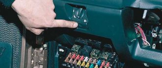
I'm looking for the cause of the fuel pump failure by checking the fuse, which is located
Under the side panel in the depths there is a fuse box, relay and ECU .
Relay and fuse box enlarged
First, I checked fuse number 3, took it out of its socket, inspected the condition of the contacts and checked the integrity with a device, the fuse turned out to be intact (by the way, 15 amperes )
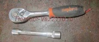
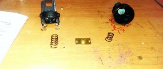
this did not help, then I checked relay number 4 . To do this, unscrew the nuts indicated by the arrows to remove the relay and install a known good one. Where can I get a working relay? high beam relay in the mounting block for the duration of the check ; it is exactly the same as the fuel pump relay. This did not help, I removed the rear seat under which there is a gas tank with a submersible pump.
Further opens before us
Before performing the above actions, I checked the power circuit (+)(-), i.e. The ground of the fuel pump at connector number 5 can be checked using the test lamp and the result is positive, I checked the continuity of the circuit on the pigtail at connectors numbers 4.6
It may happen that there is no power circuit ( + ) or ( – ) on connector number 5 . If those . ground does not reach the connector, you need to check the connection to the body. My power supply circuits are ringing.
The ground connection point is difficult to access; to get there you need to dismantle the upper and lower lining of the floor tunnel.
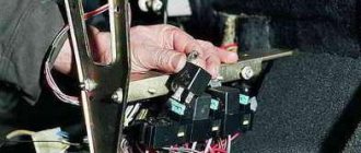
I checked the power circuits reach connector number 4 , but the fuel pump does not work, then I performed the above steps as shown in the figure, and removed the fuel module with the fuel pump from the fuel tank. Removed the pressure ring and gasket
Carefully pulled the fuel module out of the tank a little, tilting it towards the right door of the passenger compartment so as not to bend the float arm of the fuel gauge sensor (FLS)
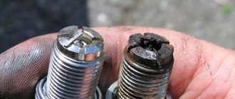
I disassembled the fuel module. Separately, I checked the pump directly from the battery. The pump is running. I checked the connectors and found the cause of the failure; it turned out that the positive contact of the connector (in the form of a pin) at the bottom under the casing was slightly burnt. I cleaned the contact (in the form of a pin) of the connector, but I couldn’t clean the other side of the connector.
I bought it complete with float.
I assembled the fuel module without installing it in the gas tank, checked it, it works. The pump must be installed with the arrow pointing towards the trunk. Installed and drove the fuel pump works fine.
Join the group and you will be able to view images in full size
All VAZ-2112 sensors 16 valves and their location: diagram and description
The efficient operation of the injection engine is ensured by a set of sensors. They all connect to the ECU. Lada hatchbacks of the 2112 family were produced only with injection engines, and two varieties of these internal combustion engines are 16-valve. We will talk about them further. All VAZ-2112 sensors, their location and appearance will be shown in the photo.
The excess oil pressure sensor, which is not connected to the ECU, is shown in the video.
Methods for troubleshooting
Troubleshooting is not a complicated process and even novice car enthusiasts can do it (the author of the video is Avtoelektika VC).
First of all, you should check the integrity and condition of the wiring.
Using a multimeter, you need to test the wiring. Damaged or torn sections should be replaced intact or soldered. If there are traces of oxidation processes on the contacts, they need to be cleaned.
If the LEDs burn out, they need to be replaced in pairs. If the breaker fails, it must be replaced with a new one, as it cannot be repaired. Before replacing, turn off the vehicle's power by removing the negative terminal from the battery. Then disconnect the power wires from the breaker. Next, you need to loosen the lock nut and unscrew the main nut securing the switch to the bracket.
Why do they do the de-mining?
During the operation of the car, you may encounter the fact that the electrical on-board network literally “sags,” especially at times of peak loads (simultaneous activation of the dimensions, low and high beam headlights, various heated mirrors and windows in parallel with the use of the air conditioning system, electric windows, powerful acoustics and other devices).
Also, voltage dips can occur for no apparent reason, affecting the stability of the internal combustion engine, its ignition system, ECU, sensors, servos and other electrical devices. This can happen if oxidation has occurred in the place where the negative terminal is normally attached to the body, the contact has broken down, or corrosion has appeared. The automobile electrical network naturally begins to operate unstably.
In the first case, additional demining of the engine is often necessary due to the fact that the car body is old, the standard place for attaching the mass has become unusable, etc. Regarding improvements and tuning, there is an opinion that additional de-mining allows a more even distribution of electricity in the vehicle’s on-board network compared to using the standard negative terminal.
Video instructions: VAZ 2110 where the mass of the fuel pump is located
13 years on the forum
From: Belgorod
Car: VAZ 21120, opal, 2001, 1.5 16V, M 1.5.4N
Added: January 22, 2010 23:30 Message title: Where is the mass of the fuel pump? –> In general, I started it today and warmed it up. bam, it started, I started it, all the signs of a non-working fuel pump, I listened, it’s definitely not working. It was -17 outside at that time. I was scared and wasn’t even standing near the house yet. In short, a tester in a car is a thing. I called, there is no mass! At -17 I didn’t want a driver, so I threw in an additional temporary wire and drove off. So, I don’t want to disassemble half the car, tell me where the fuel pump gets the power? Return to top krot 21224
9 years on the forum
Added: January 22, 2010 23:35 Message title: –> I don’t agree with the fact that you’ll have to disassemble less than half the car. (just kidding), but the weight of the fuel pump was screwed at the factory to one of the bolts securing the handbrake. I discovered it myself when I was changing the handbrake lever, unscrewed the handbrake and decided to drive the car into the garage, well, to make it easier to install, bam it wouldn’t start, I started digging around and found it. mainly to the rear handbrake bolt which is closer to the driver's seat. Return to top maxxic
13 years on the forum
From: Belgorod
Car: VAZ 21120, opal, 2001, 1.5 16V, M 1.5.4N
Added: January 22, 2010 23:38 Message title: –> Damn it. Dunduk I. ))) I recently unscrewed the handbrake, I haven’t even put everything back together yet. And I saw it.. I forgot completely.. in a hurry I screwed on the handbrake and drove off.. it would have been better if it didn’t work right away.. apparently it got caught right away somewhere, I’ve been driving for a week “without the weight of the fuel pump” Return to the beginning krot 21224
9 years on the forum
Added: January 22, 2010 23:48 Message title: –> Perhaps the bolt was not tightened all the way, maybe it just needs to be tightened. Return to top maxxic
13 years on the forum
From: Belgorod
Car: VAZ 21120, opal, 2001, 1.5 16V, M 1.5.4N
Added: January 23, 2010 09:48 Post title: –> krot 21224 wrote:
Perhaps the bolt is not fully tightened, maybe it just needs to be tightened. no, I completely forgot about it (the mass), the wire is lying somewhere under the noise, unfastened.. today I’ll try to pull it out from there and screw it on. Return to top where is the mass of the VAZ 2110 fuel pump
Basic principles
It doesn’t matter what kind of engine the Lada is equipped with - it could be a VAZ 2110 injector or a 2110 carburetor - the basic electrical components in this model will not be different.
Below are the main features that the VAZ 2110 wiring has:
- Any electrical equipment, as well as devices that are powered by electricity, is based on a single-wire connection. Lada engineers equipped the electrical wiring with wires of different colors, and each of them is responsible for the operation of certain functions. Accordingly, certain devices will be connected to the circuit through a specific wiring harness. Thanks to this, the car enthusiast has the opportunity to understand the nuances of the wiring himself, especially since, if necessary, he himself will be able to repair certain elements.
- The VAZ 21102 has 8 or 16 valves, it makes no difference, the minus is the ground, that is, it is connected to the vehicle body.
- As for the positive cable, on an 8- or 16-valve engine it will always be red. So, if the VAZ 2110 wiring is being replaced or repaired, there is no need to change the color of the wires, otherwise you will confuse yourself in the future.
- Each equipment or system associated with the vehicle’s electrical circuit is equipped with a separate cable harness.
- The tenth model of the VAZ family is designed in such a way that when the battery is activated, the entire electrical circuit and equipment operate under voltage. Therefore, when performing any work related to the on-board network, you should always disconnect the battery.
- Remember that there is also a contactless system. As a rule, it is necessary in order to create a high-quality spark when starting the engine, which also contributes to better combustion of the combustible mixture. For the normal functioning of such a contactless system, it is necessary to use high-voltage cables (the author of the video is MR. BORODA).
Basic principles
Regardless of the type of engine used, the basis of the wiring used in the VAZ 2110 car is the same. It's easy to find a diagram, but not so easy to understand.
Let's look at the basic principles of wiring.
- All equipment and devices powered by electricity in the VAZ 2110 are based on a single-wire connection. VAZ designers specially provided for wires of certain colors to each be responsible for their own functions. Therefore, certain equipment is connected using wires of their own color. This allows you to independently understand the wiring, make it easier to carry out repair work and not spend money on car repair services.
- The downside to the VAZ 2110 is that the mass is the car body itself.
- The positive wire of the batteries on the top ten always comes only in red. Therefore, when making repairs, try not to change the color of the wire, so as not to confuse yourself.
- For each system that is connected to the electrical system, it is equipped with its own separate wiring harness.
- The VAZ 2110 is designed in such a way that when the battery is turned on, all electrics and electrical equipment are energized. This is related to the most common recommendation, which you have seen more than once in our materials, where we described the repair or replacement of certain components - disconnecting the negative terminal from the battery.
- Do not forget about the existence of the so-called contactless system. This system is required to create a high-quality spark, which is simply necessary to ensure combustion of the air-fuel mixture. In order for a contactless system to function, high voltages are indispensable.
Carburetor models
The first versions of the VAZ 2110 model, which the domestic plant began to produce, were equipped exclusively with carburetor engines. Only after some time more modern injection versions appeared. They are objectively better. But this does not take away the fact that many have dozens of them under the hood with a carburetor.
Are there any significant differences in terms of electrical circuitry between a carburetor and an injector? We can say no. The carburetor systems used are almost entirely the same as on the more modern version.
Also, you will not encounter serious problems in the form of electrical wiring if you suddenly want to replace a carburetor engine with an injection engine or equip the car with additional electrical equipment. You will even find identical plugs in the engine compartment.
The only nuance of switching from a carurator to an injector is the need to install additional wiring from the fuel pump to the on-board computer.
Stories from our readers
“Fucking basin. "
Hi all! My name is Mikhail, now I’ll tell you a story about how I managed to exchange my two-wheeler for a 2010 Camry. It all started with the fact that I began to be wildly irritated by the breakdowns of the two-wheeler, it seemed like nothing serious was broken, but damn it, there were so many little things that really started to irritate me. This is where the idea arose that it was time to change the car to a foreign car. The choice fell on the melting Camry of the tenth years.
Yes, I had matured morally, but financially I just couldn’t handle it. I’ll say right away that I am against loans and taking a car, especially not a new one, on credit is unreasonable. My salary is 24k a month, so collecting 600-700 thousand is almost impossible for me. I started looking for different ways to make money on the Internet. You can’t imagine how many scams there are, what I haven’t tried: sports betting, network marketing, and even the volcano casino, where I successfully lost about 10 thousand ((The only direction in which it seemed to me that I could make money was currency trading on the stock exchange, they call it Forex. But when I started delving into it, I realized that it was very difficult for me. I continued to dig further and came across binary options. The essence is the same as in Forex, but it’s much easier to understand. I started reading forums, studying trading strategies. I tried it on a demo account, then opened a real account. To be honest, I didn’t manage to start earning money right away, until I understood all the mechanics of options, I lost about 3,000 rubles, but as it turned out, it was a precious experience. Now I earn 5-7 thousand rubles a day. I managed to get the car buy after half a year, but in my opinion this is a good result, and it’s not about the car, my life has changed, I naturally quit my job, I have more free time for myself and my family. You’ll laugh, but I work directly on the phone)) If If you want to change your life like me, then here’s what I advise you to do right now: 1. Register on the site 2. Practice on a Demo account (it’s free). 3. As soon as you get something on the Demo account, top up your REAL ACCOUNT and go to REAL MONEY! I also advise you to download the application to your phone, it’s much more convenient to work from your phone. Download here.
- The controller controls the on/off of the additional starter relay depending on the crankshaft speed and the time the starter cranks the engine.
- After setting the ignition key to the “Starter” position and the crankshaft rotation speed not exceeding 500 min1, the controller sends a signal to an additional relay and thus turns on the starter.
- After being turned on, the starter will work until the ignition key is in the “Starter” position for no more than 20 seconds, provided that the “correct” password has been received from the immobilizer and the crankshaft speed has not increased to 500 min1. This prevents the starter from turning on when the engine is running and its overheating during prolonged cranking.
Wiring test on non-working brake lights
Let's look at the basic diagram: the brake lights and the reversing lamps have a common ground pin. If contact with this pin is broken, the reverse lamps will not turn on. Well, brake lights too.
Connector for connecting “internal” lights. On the left side there is a connector through which the wiring goes to the fifth door. The connector has black and red wires. Check the voltages on them. Most often the ground on the black wire does not ring. But maybe the connector itself needs to be cleaned.
Usually, if the ground breaks, another pin is used - the one that is connected to the glass heating coil. If the “plus” does not come to the red wire, we check the “frog”. It's simple here:
- Disconnect the connector with two wires from the limit switch;
- Using 17mm wrenches, loosen the two nuts: holding the lower nut, rotate the upper one;
- The end switch is removed as an assembly and checked with an ohmmeter.
By the way, one of the connector terminals receives a voltage of “12 Volts”. Check it!
If all the steps do not lead to results, there is only one thing left: contact a qualified electrician. We wish you success.
Gasoline pump (fuel pump)
Gasoline pump (fuel pump) is a motor that drives gasoline, creating operating pressure in the fuel rail of the car. The fuel pump is part of the fuel module.
Fuel module
The fuel module is a single unit, which includes the pump itself, a fuel level indicator sensor assembled with a plastic float, an intake chamber, and a filter (mesh).
The fuel module for 1.5 and 1.6 liter engines is different.
Fuel module for engine 2111 (1.5I) – CODE 2112-1139009-12
Fuel module for engine 11183 (1.6I) – CODE 21101-1139009-01
Signs of a fuel pump malfunction
– the car won’t start
A possible reason could be a non-working or semi-working fuel pump. The fuel pump must create a certain pressure in the fuel system for normal operation. But the cause of the malfunction can be not only the fuel pump; in any case, the first thing you need to do is measure the pressure in the fuel rail, check the spark and then draw the appropriate conclusions. More detailed information can be found here.
– the fuel pump does not “buzz” after turning the ignition key
Here, most likely, the issue lies in the wiring to the fuel pump. A separate article is devoted to this problem.
– interruptions in engine operation
– the car jerks at low speed
Again, the fuel pump itself may be fine; here the problem may be the low-purity filter (mesh) under the fuel pump.
What pressure should the fuel pump create?
The pressure created by the fuel pump must be at least 3.2 bar.
Operating pressure in the fuel rail for a 1.5L engine:
From 285 to 326 kPa
For 1.6L engine:
From 375 to 390 kPa
If the pressure does not correspond to performance indicators, then the following elements may be possible causes of the malfunction:
– small and large filters
How to replace the fuel pump?
The fuel pump must maintain constant pressure. If at 3000 rpm the pressure begins to gradually drop, then the fuel pump simply does not have time to pump. This fuel pump needs to be replaced. To replace the fuel pump, use the article
Where is the ground for the fuel pump (fuel pump)?
The weak point on Samara is the weight of the fuel pump. Due to oxidation or poor contact, the car begins to start poorly, and in general there are problems with starting the engine. The fuel pump ground mount is located under the handbrake lever mount.
In any case, the first thing you need to do is check the pressure in the fuel rail, then draw conclusions. Home page
Understanding the oxygen sensor
It is necessary to determine the sensor articles not by the engine model or even by Euro standards, but only by the ECU unit.
Types of oxygen concentration sensors (OCC)
The number of oxygen sensors can be two or one - it all depends on environmental standards. AvtoVAZ also used two types of sensors - 0 258 005 133, 0 258 006 537 (BOSCH part numbers). The first of them are compatible with BOSCH M1.5.4, MP7.0 and January 5.1 controllers. Newer sensors were connected to the BOSCH M7.9.7 ECU (January 7.2). The two different types of sensors differ even in appearance.
The ECU unit in “Dozens of VAZs” is located under a plastic cover. It is located near the front passenger's foot.
The red arrow marks the first, that is, the main sensor. The top photo corresponds to engine 21124 (1.6 l).
Sensor locations (21124 and 21120)
VAZ-21120 engines (1.5 l) could meet the Euro-3 standard, and then an “extended” catalyst was welded behind the main sensor. The second sensor was located behind it, that is, behind the “can”. Let's clarify:
- The Euro-2 standard corresponds to a design with one sensor (main);
- During the transition to Euro-3 standards, a second sensor was added (blue arrow).
By the way, the 24th engine can meet Euro-4 standards.
Where to attach the wires?
The following bundles of additional mass are often used in the engine compartment:
- The “minus” of the battery is the body (attached to the rack mount to the “glass”).
- Generator housing stud – Body.
- Generator housing – Engine housing – Motor housing.
This is all done to eliminate current loss in the generator-generator mount-engine-battery circuit section, as well as for additional protection of electrical equipment from failure.
Let's look at everything using an example: Bad ground with ECM.
Problem: On a warm engine, the throttle position sensor (TPS) of the VAZ is in the open position by 2% (at idle). As it turned out, the TPS opens precisely at the moment the fan is turned on.
Conclusion: poor contact between the ECM and the car body.
What are we doing? We take an additional insulated wire (3x2.5 sq. mm) and lay it from the battery negative to the instrument panel frame, onto the ECM ground mounting stud. We securely fasten the contacts at both ends of the wire.