The procedure for adjusting the VAZ-2101 valves is an extremely important procedure, which determines the full operation of the entire internal system of your car. If you don’t know, don’t know how, can’t and have never tried, it’s better to trust the service station technicians who will do the necessary work. Sometimes it's better to pay the extra money but still have peace of mind, rather than the other way around.
In order for the engine to work stably, the car to be powerful, the engine to start normally, the valves must be adjusted in such a way that the entire system is not disturbed and works harmoniously from the spark to the moment of exhaust. You can carry out similar work yourself, that is, with your own hands, which will greatly reduce the expenditure of financial and time resources used for this.
Before you start adjusting the valves of your car, you need to prepare the necessary tools, since during the work it is not very pleasant to run around and look for forgotten things, simultaneously returning to a place that requires concentration and attention.
You will need several tools, without which you will not be able to make the correct adjustment, namely:
- 0.15 mm flat probe A.95111;
- the presence of a special device that can adjust the gap located between the camshaft cams and, in fact, the levers;
- spare gaskets for valve covers (a wide variety of options are possible - from replacing worn ones to the fact that you accidentally ruin something);
- screwdrivers included;
- socket and open-end wrenches included in the set.
Lightweight VAZ valves, specifics
The most important thing in modified valves is the donor. In Russian: we won’t make candy out of shit. Once I fell for the “client’s cry” and tried to make a modified version from the “Chelyabinsk donor”. The only advantage of Chelyabinsk residents is heat-resistant steel. The rest...turn off the lights and drain the water. Initial measurements showed that the axial runout of the chamfer on some valves reached 2-3 hundredths, which means that the valves can then be ground in until they turn blue. I also had to modify the chamfer. When all the costs were added together, the price exceeded the final product if the donor had been a high-quality German or Polish valve. Our “tuners” usually take Samara valves as a basis. Of course, the main argument is: well, this is a pipeline supplier. I will not argue. I am still ready to consider them as a “standard spare part”, but never as a donor.
Do-it-yourself adjustment of VAZ 2101 valves
Valve adjustment is a very important procedure, on which a lot depends, for example: stable engine operation, fuel consumption, power and normal engine starting. Not all motorists know how to adjust valves; the vast majority entrust this work to service station specialists, others turn to friends and acquaintances for help, and there are those who know the adjustment procedure and do it themselves.
Today I will talk about how to adjust the valves on a VAZ 2101 with your own hands.
Before you begin adjusting the VAZ 2101 valves, you need to acquire all the necessary tools, so as not to be distracted later, for this work you will need the following set:
- Flat feeler gauge A.95111, its thickness is 0.15 mm or a special device for adjusting the gap between the camshaft cams and levers.
- Spare valve cover gasket (you never know what might happen, you'll break it by accident.)
- Screwdriver Set.
- Set of socket and open-end wrenches.
Checking the quality of work
After completing the repair, it is necessary to check the operation of the engine. First, we install all the dismantled elements in place and screw in the spark plugs. After starting the engine, there should be no knocking of valves or other extraneous noise. We recommend carrying out checks for 15-20 minutes - this will ensure that the cylinders are operating normally even after heating.
It is not difficult to adjust the valves on the VAZ-2109 model yourself. You can do this work yourself, the main thing is to have a special kit and a couple of hours of free time. Using step-by-step instructions and an adjustment diagram, you will do the job efficiently and save on a trip to the car service center.
Why are guide bushings needed?
At the beginning and middle of the last century, car cylinder heads were made of cast iron, and the valves were simply inserted into precisely drilled holes. But subsequently, manufacturers abandoned cast iron heads due to their heavy weight and insufficient removal of excess heat, and they were replaced by lightweight cylinder heads made of aluminum alloys. These metals have excellent thermal conductivity, but have little resistance to wear from friction.
To solve the problem, a guide sleeve was invented - an intermediary between the soft alloy of the cylinder head and the steel valve stem, which constantly moves up and down during operation. Made of cast iron or special bronze, it is securely pressed into the cylinder head body, and the valve is inserted inside with minimal clearance.
The engine diagram shows the location of the guide bushings
The bushing itself is a hollow cylinder, made exactly to size for a specific car model. The outer surface is polished and smooth to the touch, and the inner surface has a spiral-shaped groove in the form of a thread. Motor oil moves along it, lubricating the valve axis and reducing friction. A shallow recess is made in the upper part of the guide part, into which a retaining ring is inserted.
On the left is the bushing for the exhaust valve, on the right is for the intake valve
Bronze bushings for VAZ 2109 all look the same
Bushings perform the following functions:
- as the name implies, they direct the movement of the valve so that its plate is clearly aligned with the seat and fits tightly to it;
- take on the load from the friction force that occurs during the translational and reciprocal movement of the valve stem;
- the valve cup gets very hot in the combustion chamber, and the bushing transfers this heat to the aluminum alloy of the cylinder head;
- Thanks to a special groove, the part provides lubrication of rubbing surfaces.
Cast iron parts of VAZ 2106 - intake bushings are shorter than exhaust bushings
When the element is pressed into the cylinder head hole, its upper part of smaller diameter protrudes several millimeters above the surface. This is necessary to install an oil seal on it (also known as a valve seal), which prevents lubricant from the upper part of the engine from entering the combustion chamber through the inner hole of the bushing.
This is what the protruding part looks like where the oil seal is put on
Model of operation of the gas distribution mechanism
A fresh fuel-air mixture saturates the cylinder through the intake ports. Exhaust gases exit through the outlets. These two interrelated processes must occur stably at certain intervals. In this regard, it is necessary to periodically adjust the intake and exhaust valves on the VAZ 2101
, thereby ensuring reliable and productive engine operation.
The camshaft determines when one of the aforementioned transitions needs to be made. It consists of cams profiled according to a certain law. It is the latter, constantly in contact with the rocker arms, that give commands to close or open the holes. The energy for the functioning of the mechanism is transmitted from the crankshaft by a double chain.
How to adjust valves
All procedures must be carried out only on a cold engine. This is done to ensure that the setup results remain standard: this is exactly what they do at the manufacturing plants. It is worth noting that the procedure for adjusting the valves on each car is different: you can find it out from the instructions for the car or the relevant literature. The process is carried out by screwing in or unscrewing special adjusting screws, or by selecting flat washers. Each of these options is considered separately.
Using special tools
Engine valves are adjusted using a set of feeler gauges or a special rack and indicator. Both methods are quite widespread: the first is simple, accessible and requires minimal financial and time costs. To apply the second method, you will have to buy a device and a special device.
Adjustment using feeler gauge and locknuts
This method of setting the timing belt is typical for Russian rear-wheel drive cars (“classics”). Algorithm of actions:
- Remove the air filter housing and disconnect all tubes, cables and levers from the valve cover. To make it easier to turn the engine crankshaft, remove the spark plugs.
- Remove the valve cover and the front timing belt cover (if there is one, it may also be a chain).
- Set the piston of the cylinder from which the procedure will begin (for example, in the Zhiguli “classic” it is the 4th) to the top dead center position: the valves will be in the closed position.
- Observing the indentation mark on the engine shaft pulley, rotate it until it coincides with the mark on the lower front cover of the BC. The recessed point on the timing shaft sprocket should also coincide with the mark on its “bed” (housing).
- Use an open-end wrench to hold the adjusting hardware and at the same time loosen the locknut. Next, you need to use a set of feeler gauges to adjust the valves. Select the thin plate you need and insert it between the rocker arm and the valve stem. When adjusted normally, the feeler gauge will pass through with little friction. The gap value must be adjusted according to the table, which is different for each car (for VAZ2101-07 - 0.15 mm). Now tighten the locknut and check the clearance again. Repeat the operation if necessary. Follow the order of valve adjustment: for example, for a VAZ classic: 8-6, 4-7, 1-3, 5-2.
Adjustment using washers
This type of timing adjustment is more typical for front-wheel drive cars. To produce it, you need:
- Remove the valve cover.
- Find the marks on the engine block, timing belt pulley and, turning the crankshaft clockwise, make sure they match. As a result, the first piston will be in the TDC position.
- Determine the gap between the shim and the camshaft cam (they are the first when viewed from the pulley side).
- If there is a larger or smaller gap, select another washer (each has a corresponding marking; if not, use a caliper, or better yet, a micrometer).
- After installing the washer, check the gap again: the permissible deviation is no more than 0.05 mm in both directions.
- Do not forget that the gap size for the intake and exhaust valves is different - this parameter must be found out from the operating instructions for a particular car.
Adjustment using indicator and rack
This method is considered more accurate and was especially popular during the USSR. This adjustment method is good for engines that have been in operation for a long time, since the device and measuring rod take into account the wear on the surfaces of the parts. Progress of the procedure:
- Remove the valve cover, having first disconnected the levers and cables from it.
- Rotate the engine shaft until the marks match, just as when adjusting the valves using a feeler gauge.
- Take the rack and fix it on the cylinder head (fastening is carried out to the studs of the camshaft housing). There is a small nuance: you do not need to completely screw in all 3 nuts securing the rack, otherwise it will dangle. First of all, tighten the outer hardware, then begin to unscrew the middle bolt until the rail becomes motionless.
- Take the dial indicator and secure it to the rail, and place the device’s foot on the edge of the valve cam.
- Using the included grip, grab the cam and pull it up: the indicator needle should pass 52 divisions (at an air temperature of +20 degrees). If this is not the case, then you need to adjust the valve using one of the two methods described above.
Valve timing
And even if modern valves can move much faster than their ancestors a hundred years ago, the properties of the flammable gases they control have remained virtually unchanged. They also easily compress when impacted, and also stubbornly continue to strive in all directions equally, obeying Pascal’s law, which means they are not in a hurry to move to where they are asked. And to ensure that the cylinder is filled as much as possible in such a short period of time, the intake valve begins to open before the piston completes its exhaust stroke. And the exhaust will begin to open before the power stroke is completed, so that the hot gases under pressure in the cylinder do not create excessive resistance to the movement of the piston when the exhaust stroke begins.
The moments of time when the opening begins, the duration of their stay in the open and closed states, form the engine valve timing phases. The movement of the valves is controlled by the camshaft, in the form of cams the information about the valve timing of your engine is “encrypted”. The phase values are selected when designing the engine depending on its design, purpose, and operating conditions. In the most advanced engines, these phases can change for specific operating conditions and loads at a given time. In conventional engines, the only effective way to change valve timing is to replace the camshaft. Changing the valve timing by installing an original camshaft is one of the methods of advanced engine tuning. Agreeing to such a procedure, we must understand that an increase in engine power will occur at the expense of deterioration in efficiency and a decrease in the service life of its parts. Therefore, this setting is usually used on sports cars, where the resource, efficiency and environmental friendliness of the engine are of secondary importance.
In a real engine, when the piston is near its top dead center (TDC) and bottom dead center (BDC), the intake and exhaust valves are open simultaneously
Springs
Basic data for checking the outer valve spring
Lever spring check diagram
A – free size; B – dimension under load
1. Make sure there are no cracks on the springs and whether the elasticity of the springs has decreased, for which check the deformation of the springs under load (Fig. Basic data for checking the outer valve spring, Fig. Basic data for checking the internal valve spring, Fig. Diagram for checking the lever spring ).
2. For lever springs (see Fig. Lever spring check diagram) size A (spring in a free state) should be 35 mm, and size B under load 51–73.5 N (5.2–7.5 kgf) - 43 mm.
How to adjust valves on a VAZ 2110
There is no need to purchase shims in advance. They are relatively expensive. Initially, you have to establish the size of the gaps and only then buy the required number of washers with the exact dimensions. It is better to carry out work in a garage with good lighting. The roof and walls will protect from unwanted wind and rain, which can carry dirt into the open camshaft.
Disassembly
If everything is ready, then we proceed to the first part of the repair - dismantling the parts:
- disconnect the terminal from the battery;
- remove the air filter housing (on a carburetor engine);
- disconnect the crankcase gas hoses and the throttle cable bracket from the valve cover;
- unscrew the bolts of the timing case. Remove the cover and gain access to the pulley;
- unscrew the spark plugs (this will make it easier to rotate the crankshaft to find TDC and BDC);
- Unscrew the valve cover nuts and remove it.
Before direct tuning, you should remember the mechanism of operation of the timing belt. Namely, the operating order of the valves (in our case, a VAZ 2110 with an 8-valve injector).
| Camshaft rotation angle, degrees | Cam No. (counting from camshaft pulley) | |
| Exhaust (gap 0.35.mm) | Inlet (gap 0.20mm) | |
| 0 plus 2-3 teeth | 1 | 3 |
| 90 plus 2-3 teeth | 5 | 2 |
| 180 plus 2-3 teeth | 8 | 6 |
| 270 plus 2-3 teeth | 4 | 7 |
| Crankshaft rotation angle, degrees | N of the cylinder in which the compression stroke occurs (end) | N adjustable valves (cams) |
| 4 | 8 and 6 | |
| 180 | 2 | 4 and 7 |
| 360 | 1 | 1 and 3 |
| 540 | 3 | 5 and 2 |
The procedure for adjusting the valves on a VAZ 2110 with an 8-valve engine must be performed in the same sequence as in the table. As for installing valves on a VAZ 2110 with 16-valve engines, the diagram looks completely different.
| valve | 1 class (you) | 2 cells (ch) | Zkl (vp) | 4th grade (you) | 5th grade (you) | 6 cells (ch) | 7 cells (vp) | 8th grade (you) |
| Should ±0.05 | 0,30 (0,35) | 0,20 | 0,20 | 0,30 (0,35) | 0,30 (0,35) | 0,20 | 0,20 | 0,30 (0,35) |
| largest gap | 0,25 | 0,35 | 0,40 | 0,35 | 0,40 | 0,30 | 0,30 | 0,40 |
| washer | 4,30 | 3,82 | 3,52 | 4,22 | 4,50 | 4,27 | 3,87 | 4,25 |
| What kind of washer is needed | 4,25 (4,20) | 3,97 | 3,72 | 4,27 (4,22) | 4,6 (4,55) | 4,37 | 3,97 | 4,35 (4,3) |
Adjustment
After removing the valve cover, it is necessary to remove any remaining engine oil near the tappets. This can be done with a medical syringe or a rubber bulb. If there is a retaining rod, you should install it on the two outer studs intended for fastening the cylinder head cover.
Then, we proceed to the second part of the repair and do the following:
- We set the top dead center by aligning the marks of the camshaft pulley and the inner timing case. There are two ways to do this. Hanging and rotating one front wheel. Use a spanner wrench (head) to rotate the camshaft by the pulley mounting bolt, but this operation is dangerous due to breakage of the mounting bolt;
- After finding the top dead center, turn the camshaft slightly so that the pulley moves 40-50° from TDC (this is 2.5-3 teeth). We put our mark, from which we will then rotate the camshaft several more times, making additional marks;
- We measure the thermal clearance of the first valve (exhaust) by slipping one of the feeler gauges (0.35/0.4/0.45 mm) between the camshaft cam and the pusher. Nominal clearance 0.35 mm;
- if the first probe passes freely, then take a larger size (0.4 mm). The pitch is 0.05 mm;
- if the 0.4 or 0.45 probe does not pass, then it is necessary to replace the adjusting washer;
- We turn the pusher with the groove towards us, press it with the lever of the locking rack and take out the used washer with tweezers. Its inner side contains numbers with the original size;
- to calculate the required value, you must use the formula H = B + (A - C). Where:
- H—thickness of the new washer, mm;
- B—thickness of the used washer, mm;
- A - measured gap, mm;
- C—nominal gap, mm.
- The resulting result H is written down in a notepad. You will have to buy a washer of this exact size for the repair valve, rounding up the value;
- according to the table, we move on to the third valve (intake), its nominal clearance is 0.2 mm;
- measure the gap by inserting feeler gauges in order: 0.2/0.25/0.30 mm;
- write down the size of the probe, which is not included in the thermal gap;
- take out the washer and calculate the repair size using the above formula;
- then, according to the table, we turn the crankshaft several times to the indicated degrees and perform the operation with all the valves;
- We go to the store and buy the required number of adjusting washers of the required thickness, according to calculations;
- We install the washers in the pushers, according to the notebook;
- all valve clearances on the VAZ 2110 should be restored to the nominal sizes of 0.2 and 0.35, thanks to the use of adjusting washers;
- checking new thermal gaps;
- after replacing the washers, it is necessary to put the dismantled parts in place;
- we start the engine and observe its operation.
Valve lid
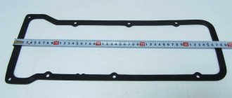
The valve cover covers and seals the timing belt, preventing grease from camshaft, valves and other parts from leaking out. In addition, new engine oil is poured through its neck when replacing. Therefore, a sealing gasket is installed between the valve cover and the cylinder head, which is changed every time after repair or adjustment of the valves.
The valve cover gasket must be replaced after each valve adjustment.
Before replacing it, you should thoroughly wipe the surfaces of the cylinder head and cover to remove any remaining engine oil. Then the gasket is put on the cylinder head studs and pressed with the lid. It is necessary that the gasket fits exactly into the grooves of the cover. After this, the fastening nuts are tightened in a strictly defined sequence.
When tightening the valve cover nuts, do not use too much force as this may damage the cover surface and gasket.
Springs
Basic data for checking the outer valve spring
Lever spring check diagram
A – free size; B – dimension under load
1. Make sure there are no cracks on the springs and whether the elasticity of the springs has decreased, for which check the deformation of the springs under load (Fig. Basic data for checking the outer valve spring, Fig. Basic data for checking the internal valve spring, Fig. Diagram for checking the lever spring ).
2. For lever springs (see Fig. Lever spring check diagram) size A (spring in a free state) should be 35 mm, and size B under load 51–73.5 N (5.2–7.5 kgf) - 43 mm.
Why do you need a guide bushing?
The guide bushing can quite rightly be considered the main element on which the resource and proper operation of the “seat - valve plate” tandem depends. The material from which the part is made and its design itself are primarily aimed at working under conditions of high speeds of the valve stem fixed in it, constant high-temperature loads and the almost complete absence of lubrication in the valve-bushing pair.
Causes and consequences of deformation
The described conditions lead to the fact that during engine operation, the valve guide bushing also wears out, which is why, over time, its alignment with the valve stem may be disrupted. Subsequently, the part breaks even more and the valve begins to “walk” and does not fit tightly to its seat, and this, in turn, leads to the chamfer of the seat breaking over time. As a consequence, you can get a burnout of the valve and have to replace the seat.
Appearance of bronze guide bushings for VAZ 2108–2109 models
Also, due to the “walking” of the valve in a broken guide, the oil seals can quickly become unusable. They simply will not be able to hold oil with increased angular displacement of the valve stem. The result will be oil getting into the engine, and if you also take into account that more oil will pass through the broken bushing than usual, then the situation will not be pleasant. Carbon deposits on valves and other parts around the combustion chamber will increase, the level of harmful exhaust emissions will increase, and you may end up with a prematurely failed catalytic converter. And simply replacing the valve stem seals is not enough, as the problem will soon return again.
Why you shouldn't neglect checking
When repairing an engine, it is better to pay special attention to its head. Often it is this part of the engine that is to blame for the fact that the level of compression in the cylinders is far from the desired
When repairing cylinder heads, motorists sometimes limit themselves to only grinding the valves to their seats, believing that there is nothing particularly wearable in all-metal bushings. At the same time, checking how large the gap between the part and its valve is will be completely worthwhile. When the obtained clearance figures go beyond those recommended by the car manufacturer, then no amount of grinding in the valves or replacing the valve stem seals will protect against problems in the future.
Materials used to make bushings
For the manufacture of bushings, materials with good wear resistance and thermal conductivity are used. Among these you can find:
- special cast iron alloys;
- bronze;
- brass;
- metal ceramics.
In terms of thermal conductivity and cost, brass, along with bronze, are among the leaders, so the vast majority of bushings are made from alloys of these metals.
Nuances to consider
Most bushings have a special support collar on the outside, designed to ensure proper fixation of the part vertically in the cylinder head. If the part is smooth, then installation is carried out using a special mandrel.
For intake valves, the guide bushings should not protrude so as not to increase the aerodynamic drag of the intake channel. Exhaust valve bushings are designed to “hide” the valve stem as much as possible to protect the latter from high temperatures and better heat dissipation.
Appearance and location of the valve guide in the cylinder head
We recommend: How to properly bleed the brakes on a VAZ-2114?
The manufacturing precision of the bushings is very high. This is necessary to obtain the most accurate alignment and the best fit of the valve plate and seat during engine operation. The outside of the body of the part that is to be pressed into the cylinder head must be processed as cleanly as possible; there should be no scratches or marks on it. This ensures optimal heat removal from this accessory to the block head.
Lapping process
First, remove the head from the engine. Next, the camshaft, adjusting washers or hydraulic compensators are removed from the head.
The next step is desiccation of the valves. To do this, either a device is used, or they are knocked out with a spacer.
After this, the mounting plates and springs are removed. The valve itself is removed from the head to assess its condition and the condition of the seat.
If it has no signs of burning and its rod is not bent, then it is not necessary to change it; it will be suitable for further use.
The saddle also needs to be inspected for signs of burning. If there are traces of burning of the seat, its surface is first treated with a rolling cutter.
After making sure that there is no burning on the surfaces, the grinding process begins.
To do this, apply a little initial processing paste to the valve chamfer.
POPULAR WITH READERS: Turbocharged or naturally aspirated engine, which is better?
Next, it is put in place, and a lapping device is put on its rod. If it is homemade, then the rubber tube on the rod must be clamped with a clamp.
Then the valve is pressed against the seat using the device and grinding begins.
To do this, turn the valve 180 degrees using the knob, and then turn it in the opposite direction. These movements are used to perform grinding.
It takes approximately 5-7 minutes to treat the surface with one type of paste. time.
The valve position changes periodically. That is, it needs to be turned approximately 90 degrees. from the extreme position when grinding in, after which the process continues again with turning it 180 degrees. and return back.
It is not advisable to mechanize the process by using a drill with an attachment on the valve stem.
Drills usually have high speeds, so when grinding with them there is a possibility of overheating the valve seat and chamfer.
In this case, a screwdriver is better. But the circular motion that will be provided by a drill or screwdriver is not recommended during lapping; this operation is best performed by half-turning the valve and then turning it in the opposite direction, that is, manual lapping.
After grinding in with roughing paste, the surfaces are thoroughly cleaned with a rag to remove any remaining paste.
Then finishing paste is applied to the valve chamfer and the grinding process is repeated.
A successful result of the grinding-in will be a uniform gray matte color of the ground surfaces without any traces of holes or scratches.
So, one by one, grind all the valves, both intake and exhaust. There is no particular difference in which car engine this operation is performed on.
The valve grinding process is the same for both VAZ-2106 and VAZ-2109 and later models.
The difference in the complexity of the work for these cars can only be the process of removing the cylinder head, preparing for lapping, and the ease of access to the valves due to the slightly different shapes of the cylinder head.
Manufacturing
standard and modified “umbrella” valves are made according to my drawings and under my control. The main point: due to the complexity of the valve shape (umbrella), it is virtually impossible to make identical valves by hand. Therefore, the product is made on CNC in small batches. CNC masters have a concept - working on one sharpening point. During operation, the cutter becomes dull and “sits”, then it needs to be corrected. Empirically, the optimal number of valves was found, which is cut “on one sharpening”, then either the tool is straightened, or another cutter is installed. Pricing taking into account the equipment and the machine operator’s salary is appropriate.
Types of resurfacing procedures
Of course, the easiest way to grind the cylinder head is to contact a service specialist. There they will do it as quickly, efficiently and professionally as possible.
A detailed diagnosis is first carried out, which indicates the extent of damage and the possibility of repair. And then the craftsmen already work on the part on a specialized grinding machine. It's simple, but the price for resurfacing a cylinder head is just mind-boggling.
- Tightening the cylinder head: step-by-step description of the diagram and tips on tightening torque standards (90 photos + video)
- How to properly grind in valves at home: tips for running in engine valves (120 photos + video)
To save money and due to the fact that many people like the repair process themselves, you can try to do everything at home.
Grinding the cylinder head with your own hands is directly possible. In most cases, this will require special equipment in the form of a machine.
Adjusting valves on a VAZ 2103
Since the operation of the engine is based on the constant combustion of the fuel-air mixture in the cylinders, the cylinder-piston group heats up quite strongly, which leads to expansion of the metal.
If such a gap were absent, engine operation would be incorrect or completely impossible due to a violation of the valve timing.
The valve clearance is adjusted between the camshaft cam and a special lever
When and why adjustment is made
Valve adjustment is one of the important measures when servicing the engine on VAZ family cars. First of all, the need for such a process is related to the design of the valve mechanism. During operation of the unit, wear is formed on the contacting surfaces of the lever, the end of the valve and the camshaft cams, which affects the increase in clearance. Due to the fact that the design of the mechanism is quite simple, the adjustment can be done on your own without much difficulty.
The need to set the correct gap arises in the following situations:
- when repairing the timing mechanism;
- noise is heard from the cylinder head area;
- the mileage after the last adjustment is more than 15 thousand km;
- engine power has decreased;
- fuel consumption has increased.
After repair work on the timing mechanism, it is mandatory to adjust the valves.
A decrease in dynamics can also be associated with the carburetor
If adjusting this unit does not produce any results, the next thing you need to pay attention to is the valve
Adjustment Tools
Adjustment of the thermal gap is carried out using materials and tools, which should be in the arsenal of every owner of a “classic”:
- a set of socket and open-end wrenches (open-end wrenches for “13” and “17” are required);
- gap gauge;
- screwdrivers;
- rags.
Separately, you should focus on the probe, since a regular flat tool will not work for this procedure. You will need a wide probe with a thickness of 0.15 mm.
To adjust the thermal gap you will need a special wide probe 0.15 mm thick
Preparatory work
In addition to the fact that the adjustment is carried out on a cooled engine, partial dismantling of some of its elements will be required:
- Unscrew the nuts and remove the air filter cover, removing the filter element itself.
- We disconnect the hoses going to the filter housing, and then unscrew the fasteners.
- Using a screwdriver, unscrew the fastening of the choke cable, then remove the throttle linkage.
- Using a 10mm socket wrench, unscrew the nuts securing the cylinder head cover and remove it.
- Remove the distributor cover.
After these steps, using a special key, you will need to install the piston of the fourth cylinder to TDC. In this case, the crankshaft pulley should be installed opposite the length of the mark on the cylinder block, the camshaft gear should be installed opposite the ebb on the bearing cover, the distributor runner should correspond to the wire of the fourth cylinder.
Before starting the adjustment, install the crankshaft and camshaft according to the corresponding marks
Valve adjustment procedure
After all the marks are set, we proceed to check or adjust the gap, which should be 0.15 mm:
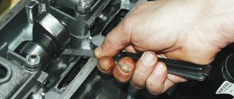
- We start work from valves 6 and 8, counting from the timing chain side. We insert a feeler gauge between the camshaft cam and the rocker and if it fits in equally tightly, then there is no need for adjustment.
- If the dipstick enters freely or with difficulty, the gap will need to be adjusted. To do this, use a wrench set to “13” to hold the head of the bolt, and use a wrench set to “17” to loosen the locknut. We insert the feeler gauge and set the desired position by rotating the bolt, after which we tighten the lock nut and check to see if the gap has changed.
- We set the gap on the remaining valves in the same way. To do this, turn the crankshaft half a turn and adjust valves 4 and 7.
- We turn the crankshaft another 180˚ and adjust valves 1 and 3.
- Lastly, we check and, if necessary, adjust valves 2 and 5.
The dipstick on all valves must be removed with the same force
At the same time, it is important to know and remember that a small thermal gap will be worse than a large one, and this can lead to burnout of the valves
Special tools and accessories
1. Rolling hydraulic jack. A standard car jack is often either inconvenient or simply useless when performing some jobs.
2. Stand (support) for the car,
adjustable in height and with a permissible load of at least 1 ton. It is advisable to have four such stands.
3. Wheel chocks
(at least 2 pieces).
4. Double-sided wrenches for brake system fittings 8, 10
and 13 mm.
The two most common types of these wrenches are the clamp wrench and the slotted socket wrench. The clamping wrench allows you to unscrew fittings with worn edges. To put the wrench on the brake pipe fitting, you need to unscrew the pinch bolt. A socket wrench with a slot allows you to do the job more quickly, but such a wrench must be made of high-quality steel with appropriate heat treatment.
5. Special forceps
for removing retaining rings. There are two types of such pliers: sliding - for removing retaining rings from holes and sliding - for removing retaining rings from shafts, axles, and rods. The tongs also come with straight and curved jaws.
6. Oil filter puller.
7. Universal two-jaw puller for removing pulleys, hubs, gears.
8. Universal three-jaw pullers
for removing pulleys, hubs, gears.
9. Universal joint remover.
10. Puller and mandrel for replacing valve stem seals.
11. Desiccant for disassembling the valve mechanism of the cylinder head.
12. Tool for removing ball joints.
13. Device for removing the piston pin.
14. Device for pressing out and pressing in silent blocks of front suspension arms.
15. Tool for removing steering rods.
16. Crankshaft ratchet key.
17. Spring remover.
18. Impact screwdriver with a set of attachments.
19. Digital multimeter for checking the parameters of electrical circuits.
20. Special probe or 12 V test lamp
to check electrical circuits of the vehicle that are under voltage.
21. Pressure gauge
to check tire pressure (if there is no pressure gauge on the tire pump).
22. A device for adjusting clearances in valve actuators.
23. Compression gauge for checking the pressure in the engine cylinders.
24. Bore gauge for measuring the diameter of cylinders.
25. Vernier caliper with depth gauge.
26. Micrometers with a measurement limit of 25-50 mm and 50-75 mm.
27. Set of round probes
to check the gap between the spark plug electrodes. You can use a combination key to service the ignition system with a set of necessary probes. The key has special slots for bending the side electrode of the spark plug.
28. Set of flat styli
for measuring gaps when assessing the technical condition of units.
29. Wide probe 0.15 mm
to check valve clearances.
30. Mandrel
for centering the clutch driven disc.
31. A mandrel for crimping piston rings when installing the piston into the cylinder.
32. A hydrometer for measuring the density of a liquid (electrolyte in a battery or antifreeze in an expansion tank).
33. Special device with metal brushes
for cleaning battery wire terminals and terminals.
34. Oil syringe
for filling oil into the gearbox and rear axle.
35. Pressure syringe
for lubricating the driveshaft splines.
36. Hose with bulb for pumping fuel.
The hose can be used to remove fuel from the tank before removing it.
37. Medical syringe or bulb
for sampling fluids (for example, if it is necessary to remove the master cylinder reservoir without draining all the brake fluid from the system). The syringe is also indispensable for cleaning carburetor parts.
When performing the work, you may also need: a technical hair dryer (heat gun), an electric drill with a set of metal drills, a clamp, tweezers, an awl, a tape measure, a wide bench ruler, a household steelyard, wide containers for draining oil and coolant with a volume of at least 10 liters.
Valve and components LADA (VAZ 2101,2102,21011,21021)
In the Dimavto.com online store, any car enthusiast buyer can choose and buy a valve and components
on lada
with an engine capacity of 1.2,1.3,1.5,1.6 liters from such manufacturers as AE, FRECCIA, Metelli. If you have questions, or they appeared during the selection process, and this prevents you from making a final decision, our support service will come to your aid. This will help you choose the right parts that match your car model.
The success of finding the required part in our store is due to the widest range of spare parts supplied to us from manufacturers from different parts of the world. Our store's policy is based on careful checking of the quality of the spare parts we sell and their compliance with the highest standards. All products sold by us are of original origin. Each buyer buying Valve and components for VAZ 2101,2102,21011,21021
selects an auto part according to the search pattern from a huge catalog that suits him best.
Spare parts search options:
- By product code;
- By car manufacturer and model.
- With tips from a parts specialist.
The selected product can be immediately added to the cart on the website online, or you can call 096 258 29 80 or 066 663 64 31 or
and place your order in person.
Our store widely presents auto parts not only by the names of well-known manufacturers, but also by groups of units and components. Using our catalog you can easily find and buy scarce chassis components, rare engine spare parts, reliable parts for brake and steering systems, gearboxes, and other vehicle components.
Using the catalog, our customers can not only find the product they need, but also read its characteristics. Here you can see a detailed image of the product from photographs and videos. Our pricing policy is always transparent and accessible.
To make it easier for you to understand the features of spare parts Valve and components and their compatibility with VAZ 2101,2102,21011,21021 by year of manufacture, modification and type of car, it is better to play it safe and clarify the nuances with our managers.
Before purchasing a replacement valve and components (inlet, outlet, bushing, guide), it is better to consult with specialists
Taking precautions will help you easily replace an old part with a new one the first time. To do this, our managers are guaranteed to help you with your choice and quickly complete your purchase with delivery.
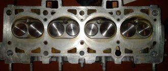
cylinder head, cylinder head device
The block head performs such important functions as:
- Provides basing and placement of gas distribution mechanism elements, fuel outlet and supply components.
- Provides gas-dynamic characteristics of the air charge, removes combustion products from the combustion chamber.
- Forms the combustion chamber and ensures its tightness, supplies and removes oil for the elements of the gas distribution mechanism.
- Ensures that the vehicle complies with environmental standards for the emission of harmful substances into the atmosphere.
The cylinder head includes:
- Guide bushings.
- Valve seats.
- Hydraulic compensator (can be supplied with a rocker arm).
- Valve rocker arm.
- Traverse.
- Spark plugs (for gas and gasoline engines).
- Springs to return the valves to their original position.
- Fuel injectors (usually used in diesel engines).
- Exhaust and intake valves.
The material from which the cylinder head is made can be aluminum (for example, the cylinder head of a VAZ 2109) or cast iron (diesel). As a rule, aluminum heads are a priority for manufacturers, since they are the most convenient to process, manufacture and repair. However, some diesel engines use cast iron heads, because the detonation properties of diesel fuel exceed the strength parameters of aluminum heads, which can lead to a reduction in service life or destruction of the cylinder head.
Cylinder heads can be divided into two types - mono-heads and individual heads. The latter have a number of advantages that are associated with maintainability, low costs and ease of maintenance. However, most of the world's manufacturers of vehicles and auto components prefer monoheads, which also have their own advantages.
The principle of operation of the cylinder head: the camshaft pushes a rod, which presses on the hydraulic compensator, and then on the rocker arm, which puts pressure on the valve, which opens and penetrates into the combustion chamber, where it is ignited by a spark from a spark plug.
This is interesting: How to independently replace a heating radiator on a Lada Kalina
Adjustment procedure
The procedure for adjusting the valves on all modifications of the 8-valve vase is the same. There are differences only in injection Grant cars, Kalina 2 with a Grant engine. They have a lightweight piston group and metal-ceramic seats. In this regard, the gaps differ upward by 0.05 mm. Knowing the order and adjustment scheme, you can adjust the valves yourself. The downside is the lack of a set of washers for adjustment. It’s expensive to go to the market to buy them every time, and it’s also expensive to buy the entire range.
Here is a detailed diagram of valve adjustment for VAZ 2108, 2109, 2114, 2115
- First you need to cool the engine. You can use an additional cooling fan from any VAZ car. Place it on top so that the airflow is towards the internal combustion engine and turn on the 12 V power supply;
- When adjusting 8 valve engines (11186, 11113 oka, 1118, 1111) with a mechanical throttle assembly, unscrew the throttle cable from the intake manifold receiver;
- Disassemble the valve cover, timing belt side casing. Disconnect the large and small breather hose going to the throttle body pipe;
- Pump out the oil near the valve cups using a syringe or bulb. It is most convenient to use a regular medical syringe with a white silicone hose at the end;
- Install a device for adjustment - a rack for pressing the valve, also called a ruler;
- Set the first adjustment position. Turn the camshaft clockwise to the mark and tighten 2-3 teeth. For cars with a lightweight piston group (Granta, Kalina 2, Priora), turn strictly by the crankshaft. If you turn the camshaft, the timing belt may slip, and if this is not noticed and the engine is driven, the valves may bend;
- Adjust in the following sequence: 1 outlet and 3 inlet valves;
- Rotate the camshaft 90 degrees. Adjust 5 outlet and 2 inlet valves;
- Rotate 90 degrees. Adjust 8 exhaust and 6 inlet ports;
- We make the last turn by 90 degrees and adjust the 4th exhaust and 7th inlet valves;
- Reassemble in reverse order. We install a new gasket under the valve cover to prevent oil from leaking out.
- On carburetor engines, everything is done in a similar order. First you need to unscrew the filter housing and the suction cable. The frequency is the same as on the injector 30,000 km.
Checking the gaps is also required after repairing the cylinder head. Especially after replacing the guides. When replacing bushings, the seats are countersunk with a special tool and deliberately recessed into the head. Accordingly, you need to follow the sequence, set the optimal gaps and repeat after 1000 km.
Adjusting the 8kL engine for gas increases the mileage between adjustments. If the engine is not intended to operate on gas equipment, the seats and valves will quickly burn out, and in order to somehow extend the service life, the clearances should be made a little larger than standard. Usually they do +0.05 mm. If the gap is not set, that is, does not expand, then the saddle is sunk a decent distance into the head. In this case, you need to measure how much the gap needs to be increased, disassemble the cylinder head and file the end of the valve. The second option would be to replace the seat or the cylinder head itself.
What is needed for grinding in
Do-it-yourself valve adjustment on a VAZ 2107
The grinding process is performed with the cylinder head removed. Therefore, in addition to tools for grinding valves, the car owner will also need a tool for dismantling the cylinder head. As a rule, these are ordinary locksmith keys, screwdrivers, and rags. However, it is also advisable to have a torque wrench, which will be needed at the stage of reassembling the head into place. The need for it arises because the fastening bolts holding the head in its seat must be tightened with a certain torque, which can only be ensured with the help of a torque wrench. Depending on which method of valve grinding is chosen - manual or mechanized (more on them a little later), the set of tools for the work will also differ.
To directly grind the valves, the car owner will need:
- Manual valve holder. Automotive stores or auto repair shops have ready-made such products for sale. If for some reason you do not want or cannot buy such a holder, then you can make it yourself. How to do it is described in the next section. The manual valve holder is used for manual lapping of valves.
- Valve grinding paste. In most cases, car owners buy ready-made compounds, since there are currently quite a lot of these products in car dealerships, including at different prices. As a last resort, you can make a similar composition yourself from abrasive shavings.
- Drill or screwdriver with reverse capability (for mechanized grinding). As a rule, grinding is performed in both directions of rotation, so the drill (screwdriver) must rotate in both directions. You can also use a hand drill, which itself can rotate in one direction or the other.
- Hose and spring. These devices are necessary to perform mechanized lapping. The spring should have low rigidity, and the diameter should be two to three millimeters larger than the diameter of the valve stem. The same applies to the hose, so that it can be placed flush on the rod. You can also use a small clamp to secure it. You also need some short metal rod with a diameter similar to the piston rod, so that it also fits the rubber hose closely.
- Kerosene. It is used as a cleaner and subsequently to check the quality of the grinding performed.
- "Sharoshka" This is a special device designed to remove damaged metal in the valve seat. Such devices are sold ready-made in auto stores. Currently, in auto stores you can find this part for almost any engine (especially for common cars).
- Rags. Subsequently, you will need to use it to wipe the treated surfaces (including your hands) dry.
- Solvent. Needed for cleaning work surfaces.
- Scotch. It is a necessary component when performing one of the mechanized cleaning methods.
Valve grinding tool
If the car owner does not have the opportunity/desire to buy a factory device for grinding valves with his own hands (manually), a similar device can be made independently using improvised means. For this you will need:
- A metal tube with a cavity inside. Its length should be about 10...20 cm, and the diameter of the inner hole of the tube should be 2...3 mm larger than the diameter of the engine valve stem.
- An electric drill (or screwdriver) and a metal drill with a diameter of 8.5 mm.
- Contact or gas welding.
- Nut and bolt with a diameter of 8 mm.
The algorithm for manufacturing a device for grinding valves will be as follows:
- Using a drill, at a distance of about 7...10 mm from one of the edges, it is necessary to drill a hole of the above diameter.
- Using welding, you need to weld the nut exactly above the drilled hole. In this case, you need to work carefully so as not to damage the threads on the nut.
- Screw the bolt into the nut so that its edge reaches the inner surface of the tube wall opposite the hole.
- As a handle for the pipe, you can either bend the opposite piece of pipe at a right angle, or weld another piece of pipe or any other metal part of a similar shape (straight).
- Unscrew the bolt back, insert the valve stem into the tube, and use the bolt to tighten it tightly with a wrench.
How to determine if the valve is tightly seated on the seat?
If you have removed the head, be sure to pay attention to the valves; at first glance, it may seem that the valves are good, but there is one sure sign that the valve definitely needs to be changed or ground in. Valves can be of different colors, white, brown, black, etc. This is normal, it all depends on the carburetor settings and engine oil consumption. But if the valve has different shades as shown in the photo below, this is a sure sign that the valve is poorly ground to the seat. This valve must be ground in or replaced with a new one, but it must be ground in.
Photo. Valve showing signs of burnout.
The valve in the photo can still be ground in, but if there is a blue tint, it is better to replace such a valve with a new one.
Other cases in which dismantling of the cylinder head is required
Of course, it is not necessary to remove the cylinder head for every breakdown. This is only necessary if major repairs are needed. Such “major” cases include:
- Gasket wear.
- Formation of carbon deposits on parts.
- Valve deformation.
- Need to replace guide bushings.
- Failure of the camshaft, etc.
Of course, repairing it yourself or through a service in any case involves certain financial costs. To ensure smooth operation of the engine, regular diagnostics of the cylinder head are necessary. It is recommended to use high-quality fuel. In addition, try to prevent the car from overheating - because of this, the cylinder head may lead.
If some points remain unclear to you, then you can visually familiarize yourself with the process of replacing valves by watching the video:
Lapping paste
During operation, it is applied to the edge of the valve and serves as fine sandpaper that rubs the valve into its seat. There are many options for lapping paste. For example, such as in the picture in the form of valves. It should be chosen based on your finances and preferred manufacturer.
The lapping paste differs in the degree of processing: from coarse-grained (for initial processing) to fine-grained (for final processing). The latter is recommended by engine repair specialists, because... the process will go faster with it. Everything depends not on the paste itself, but on the condition of the valves and chamfers and the correctness of the process. For some, a regular tube for 100 rubles will do, but for others, give them only a professional one.
If you do it yourself, it’s better to start with regular lapping paste, not the most expensive one. If something goes wrong, then buy the necessary one in the process.
"Sharoshka" for removing metal
This tool is used to restore valve seats. It represents a valve seat attachment made to fit the shape of the valve seat. It is usually fixed in a drill like a drill and is small in size.
Do you need cutters? We look at the saddles that are pressed into the head. If they are not damaged, then you can start grinding in, but if they are damaged (by burnout), then you need to treat them with special cutters. In general, the technology is as follows - first it is better to change the valve guides, then grinding in.
New valves
They are not always needed. If you find that the valves are somewhat bent, then trying to straighten them will lead to nothing except wasted effort and time. A better idea would be to head to the store and purchase a new set of valves for the engine.
When replacing valves, pay attention to quality. Their height must be the same; marks and roughness are not allowed on the rods, ends and working sealing chamfers
It is better to polish the rods to a mirror shine before installation. It is also worth polishing the plane of the plate and the “black” neck of the valve, so it will heat up less and become overgrown with soot. Do not touch the sealing chamfer, you just need to rub it against the seat.
Tool
You can use a drill and a rubber hose for this purpose. The process is as follows: we put a hose on the drill (you can use a drill, and fasten it with clamps), and put the engine valve on this hose (we fix it with clamps) with lapping paste applied.
Next, insert the valve into the seat and begin the grinding process. The main thing is not to give maximum speed to the drill; the process should occur at low speeds (400-500 rpm). If the speed is higher, there is a risk of overheating the valve seats or belts. Also, there is no need to make circular movements, but rather imitate the operation of the valve back and forth. This method is not very good and takes a lot of time.