Failure of the “vacuum seal” is a rather rare failure, but unpleasant - to slow down and stop the car, the driver has to press the brake pedal hard. A sudden failure of the mechanism while driving can provoke an accident - the driver does not have time to change lanes and apply the required force at the right time. To identify signs of critical wear of an element, it is proposed to consider the operating principle of a vacuum brake booster (VBR) and diagnostic methods in a regular garage.
VUT device
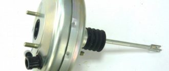
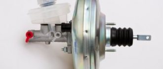
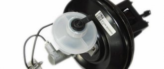
The vacuum brake booster in most cars is located near the engine shield and is a monolithic block with a turbocharger and a brake fluid reservoir.
To enhance the braking force, the VUT design uses:
- metal case;
- a separating diaphragm made of plastic material;
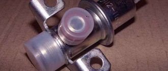
- check valve;
- pedal assembly pusher;
- follow-up valve;
- hydraulic cylinder rod;
- return spring.
Replacing VUT on UAZ vehicles
The amplifier is removed on cars produced by the Ulyanovsk Automobile Plant according to the same principle as on VAZ cars. Let's consider replacing VUT using the example of a UAZ-31519 car:
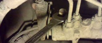
- first of all, we unscrew the two fastenings of the GTZ to the “vacuum”, usually the cylinder is secured with nuts 17, without disconnecting the brake pipes, we move it to the side;
- under the hood, in the area of the windshield, unscrew the 2 bolts of the VUT amplifier bracket, the standard bolts are 14 mm turnkey;
- in the cabin, at the connection of the rod with the brake pedal, pull out the cotter pin; for this you will need pliers;
- remove the connecting pin;
the two lower nuts of the amplifier bracket are located in the car interior, they are turnkey 17, unscrew this fastener;
- pull off the hose from the fitting of the device, dismantle the VUT;
- disconnect the bracket from the “vacuum” - to do this, unscrew the four nuts (they are 17 mm);
- the check valve is not included with the part, so we move it from the old VUT to the new one;
- We connect the bracket to the new amplifier, carry out the assembly - we install all the parts in their places.
Principle of operation
The clamping force of the brake pads in cars, the design of which does not require the installation of VUT, is pumped up by the force created by the driver when pressing the pedal. A vacuum brake booster uses differences in atmospheric pressure to create a vacuum, thereby helping to build up pressure in the brake line.
Let's start with the fact that the working diaphragm divides the body into atmospheric and vacuum (located on the GTZ side) chambers. It is connected through a pusher to the pedal. When the brakes are not applied, the follower valve maintains equal pressure in the two chambers. Depressing the brake pedal causes the follower valve to “cut” the connection. The bypass valve equalizes the pressure of the atmospheric part of the body with the engine compartment. The vacuum, which has been maintained in the VUT housing all this time, now attracts the diaphragm. As soon as the driver releases the brake pedal, the return spring returns the elastic partition to its original position.
The low pressure in the housing, which drives the vacuum booster, is created through a hose connecting the vacuum part to the intake manifold. It occurs due to the vacuum created by the piston descending to BDC during the intake of the fuel-air mixture. If the vacuum of a gasoline engine is sufficient for the normal operation of the VUT, then diesel engines are necessarily equipped with a vacuum pump designed to pump up the vacuum. Depending on the design (petal, membrane), such a device is driven by: injection pump, generator or camshaft.
Purpose and location of the unit
The first classic Zhiguli models (VAZ 2101–2102), produced without amplifiers, were distinguished by a “tight” brake pedal. To stop the car suddenly, the driver had to exert considerable effort. In the 70s of the last century, the manufacturer began equipping cars with vacuum boosters (abbreviated as VUT), which significantly increased braking efficiency and made the driver’s work easier.
The unit in the form of a metal “barrel” is installed on the bulkhead between the engine compartment and the interior of the VAZ 2107, on the driver’s side. VUT attachment points:
- the body is screwed to the partition with 4 M8 nuts;
- the master brake cylinder is attached to the booster in front on 2 M8 studs;
- the push rod of the element goes inside the passenger compartment and is connected to the brake pedal lever.
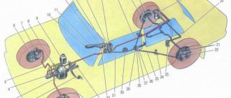
The vacuum booster of the brake system is located on the wall of the partition between the passenger compartment and the engine compartment
The booster's job is to help the driver apply pressure to the master cylinder rod using vacuum force. The latter is created using vacuum taken from the engine through a special pipe.
The vacuum selection hose is connected to the intake manifold from the side of the channel leading to cylinder III. The second end of the pipe is connected to the fitting of the check valve installed outside the VUT housing.
The VUT vacuum pipe (on the left in the photo) is connected to the fitting on the suction manifold
Essentially, the vacuum booster does the physical work for the driver. The latter only needs to lightly press the pedal for the car to begin to slow down.
VUT breakdowns
Malfunctions of the vacuum booster can affect not only the effectiveness of the braking system, but also the operation of the gasoline engine. The main types of breakdowns include:
- violation of the tightness of the system, damage to the hose ensuring vacuum;
- diaphragm rupture;
- damage to operating valves or related parts (springs, valves).
A failed brake pressure booster will not prevent your car from braking, but it can make it significantly more difficult to drive.
If you notice changes in the operation of the booster, do not rush to change the hose or repair the brake booster. On some cars, the air recirculation damper in the cabin is directly related to the operation of the amplifier. The symptoms of depressurization of this system are similar to those that appear when the VUT breaks down.
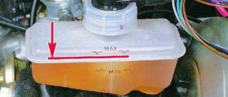
Bleeding the system
After completing any repair work that involved replacing vehicle parts, it is necessary to perform bleeding. It is carried out with the aim of eliminating air from the main line and equalizing pressure.
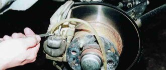
To work, you will need keys “8” and a cylinder, a jack, a transparent container, a hose and brake fluid. The car is driven onto a flat area. The fastening nuts are loosened, and then the body is raised using a jack. We unscrew the nuts and dismantle the wheel.
Remove the cap from the fitting, putting on the hose. The second end of the hose is placed in a container prepared in advance. At this time, you need to ask someone to get into the car and depress the brake pedal 4-6 times and then hold it down. After this, you need to unscrew the fitting with a key, but not all the way. Loosening will result in fluid leakage. We wait for the brake pedal to go down, only then tighten the fitting.
Bleeding is done until the brake fluid flows without air. All the same actions are carried out with the other wheel. The rear brakes require similar work. As soon as the procedure is completed, you need to add brake fluid to the reservoir and check the brakes on a calm road.
Self-diagnosis
The simple principle of operation allows you to perform diagnostics yourself. Vacuum booster repairs should be entrusted to specialists. Several simple methods will help you determine if the system is working properly:
- After running the engine for a short time, turn off the car and press the brake pedal several times. With a working amplifier, the first press will be light, and all subsequent presses will require effort. Each subsequent pedal stroke will be shorter;
- turn off the engine and wait a few minutes. You can check the VUT for leaks by pulling out the hose that goes to it from the intake manifold. If there is a vacuum, you will hear a pop of escaping air;
- With the engine off, vigorously depress the brake pedal several times in a row. Start the engine while continuing to hold down the pedal. As soon as the engine starts, a working vacuum brake booster will make the pedal “soft” and it will fail;
- One of the most common problems is air leaks. Check the vacuum supply hose for mechanical damage, as well as the tightness of its connection to the housing. In this case, urgent repair of the VUT may be required. This “suction” of air is quite enough for the gasoline engine to start to stall;
- the engine is switched off. When you press the pedal for the first time, you should hear the sound of air entering the atmospheric part of the body. If there is none, the membrane is torn or the bypass valve is faulty.
Checking the amplifier and related elements
Checking the performance of the amplifier is not difficult, and it does not require any equipment.
One of the simplest ways to check without the need to “climb” under the hood is done like this: with the engine off, pump up the brake system (press the pedal 4-5 times and fix it with your foot in the pressed position).
Then we start the engine. Immediately after starting, a vacuum will go to the vacuum chamber of the amplifier, as a result the pedal should go down a little. If this happens, the vacuum seal is working properly and there is no air leak.
If the brakes seem to be working, but when they are applied, the power plant changes its operating mode, you can check whether the booster is to blame for this: disconnect the pipeline from the intake manifold, and plug the fitting with a rubber plug (for this you can use a piece of a tube of suitable diameter, which needs to be clamped).
The improvised plug must be securely secured with a clamp.
Then we start the engine, let it run a little, and begin to press the brake pedal (you can do this on the road, but you should definitely take into account that the booster will not work).
Operating principle of a vacuum brake booster
Everyone probably knows that the brake system of a modern car is a hydraulic system.
Pressing the pedal creates pressure in the brake fluid, which presses on the pistons, and the pistons, in turn, press the brake pads against the surface of the brake discs. Accordingly, the main force and the force from which it all begins is the force of a person’s foot on the brake pedal. So, thanks to VUT, this effort can be increased several times. The vacuum brake booster consists of two chambers separated by a special membrane. The chamber located closer to the master cylinder is a vacuum chamber and is maintained at low pressure. The chamber facing the brake pedal is called atmospheric. This atmospheric chamber, with the help of a monitoring valve, can be connected either to the chamber where we create a vacuum, or to the immediate environment, that is, to an environment in which the air pressure is a certain and fairly significant value. The VUT also includes a follower valve pusher, which connects directly to the brake pedal, and another important component of the brake booster is the diaphragm return spring.
As for the diaphragm, which separates the two chambers, it is equipped with a special nickel in the center, which presses on the piston rod of the master cylinder. When you release the brake pedal, the return spring, true to its name, returns the membrane to its original position.
Now let's describe the operation of the vacuum brake booster, so to speak, in dynamics. The vacuum chamber is connected through a special hose to a device capable of creating a vacuum, or, more simply, a kind of vacuum. Such a device can be either the engine itself, if it is a gasoline engine, or a special vacuum pump. Such pumps are required to be installed in vehicles with diesel power plants. Although, recently VUTs have also begun to be equipped with pumps in gasoline-powered cars. This is necessary for consistently high efficiency of the amplifier at different engine operating modes.
When the car is moving and there is no need to brake, a rarefied area is maintained in both chambers. But, as soon as you press the brake pedal, the valve closes the connection between the chambers and opens access to the atmospheric chamber, atmospheric air at the appropriate pressure. It is this air, plus the force of the person pressing the pedal, that acts on the piston of the master brake cylinder, which ensures the injection of brake fluid into the system. Essentially, a vacuum booster allows us to use atmospheric pressure to increase braking force. As they say: everything ingenious is simple. As for amplifiers that are equipped with vacuum pumps, this solution, in addition to increasing the stability of the VUT, is almost always used for the operation of electronic assistants in driving a car. For example, it is these vacuum pumps that ensure the operation of the ESP system, which is responsible for the car’s stability on turns and corners.
How to replace a check valve?
The vacuum booster is responsible for creating vacuum pressure that can be used by the engine to increase pressure. If the valve fails, the vacuum pressure generated by the booster cannot be used effectively to power the brakes.
In the event of a malfunction, the pressure in the brakes is usually less than necessary. This can lead to accidents as the brakes will not be able to function to their full potential.
Step 1 - Locate the brake check valve.
Find your brake check valve to start working on it. The brake check valve is usually located in the engine area of the car where the engine connects to the vacuum booster. This connection can be further identified by searching for the vacuum line.
Step 2 - Remove the clips.
Most vacuum lines have clamps to hold them in place. Before you remove the vacuum line to move to the next step, you need to carefully remove all the clips. Remove the clamps carefully to avoid damaging the vacuum line. You will connect the same vacuum line at the end of the process.
Step 3 - Remove the brake check valve.
Once the vacuum line is removed, you will have full access to the brake check valve. Now you can easily remove the valve. Use a screwdriver to loosen the screws around it and a wrench for the valves. Once you do this, you can easily pull the valve out. Then use a hand vacuum pump to apply vacuum to the inlet end of the valve. The vacuum should be between 15 and 20 degrees. If the pump shows loss, it means the valve is faulty.
Step 4 - Install the new brake check valve.
Reverse the process you went through to remove the old brake check valve, install the new one on the booster. Tighten the valve with a wrench and the screws with a screwdriver. Once the new valve is installed, reconnect the vacuum line, reversing the process you used to disconnect it.
Step 5 - Check the brakes.
Once installation is complete, start the engine and check the brakes. If the brake pressure and power still seem low, the problem may be with the vacuum booster.
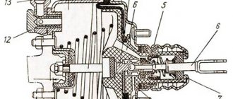
Internal diagram
- tip mounting flange;
- stock;
- diaphragm return spring;
- master cylinder flange o-ring;
- master brake cylinder;
- amplifier pin;
- amplifier housing;
- diaphragm;
- amplifier housing cover;
- piston;
- valve body protective cover;
- pusher;
- pusher return spring;
- valve spring;
- follow-up valve;
- rod buffer;
- valve body;
- vacuum chamber;
- atmospheric chamber;
- channels
- channels
Diesel fuel system air leak
Typically, airing in the fuel system of a diesel engine is caused by damage at the junction of the tubes connecting the fuel tank and filter or the filter and high-pressure fuel pump.
On diesel cars that have been produced in recent years, air penetration into the fuel system occurs more often compared to older type diesel engines. The reason lies in the different design of the hoses, the service life of which has been noticeably reduced. Previously, these elements were made of brass, but now they are made of plastic. Constant vibrations lead to wear of the plastic and rubber seals. Most often, owners of cars with a mileage of about 150-200 thousand kilometers encounter such difficulties, and suction often appears in winter.
The most popular causes of suction in such cases:
- wear of clamps and hoses;
- damage to the fuel filter seal;
- damage to the fuel pump cover seals or drive shaft;
- leaking fuel pipelines;
- damage to the return fuel line;
Signs of air leaks on a diesel car
Most often, the engine does not want to start after long periods of inactivity. The driver is forced to repeatedly turn the key in the ignition using the starter. This is accompanied by the appearance of smoke from the exhaust pipe, which is a sign of normal fuel supply. If the suction is very significant, the engine will not only have difficulty starting in the morning, but also stall while driving.
The reason is that the pump cannot operate normally at idle speed because too much air enters the chamber. At higher speeds, the fuel injection pump copes even more or less well. Such symptoms are not always caused by suction, so we advise you to check the “diagnosis” by installing transparent fuel pipes.
How to find air leaks in the fuel system of a diesel engine
Air may enter the system through a connection, fuel tank, or pipe. The search is performed quite simply - by applying pressure or by exclusion. In the first case, you need to apply pressure to the fuel tank, after which you will hear a characteristic hissing sound or see drops of fuel at the leak point. The second method is to check the elements of the fuel system one by one, ensuring that fuel is supplied from the container, not the tank. First we connect to the fuel pump and move on.
Signs of a faulty vacuum brake booster and its repair
First of all, it should be noted that the breakdown or complete failure of the VUT does not manifest itself with any obvious symptoms characteristic only of this situation. In other words, the cause of this or that sign of VUT failure may be something else. And yet, we will list the most characteristic signs of a brake booster failure:
- decreased braking efficiency;
- engine tripping at idle speed;
- the brake pedal does not press when pressed or is pressed very tightly;
As for the engine tripping, it is caused by depressurization of the vacuum hose of the brake booster, and as a consequence of this, by an abnormal supply of air to the intake manifold. If the engine stops moving when you press the brake pedal, then you need to check all the connections, clamps, and hoses in the brake booster. Accordingly, in diesel cars, this symptom does not occur, because in the intake manifold of a diesel engine, the vacuum is much weaker, and therefore vacuum pumps are used there.
There are different ways to check the performance of the VUT. You can just examine it carefully. If you find leaks, damage, distortions and leaks, they must be eliminated or the damaged unit or the amplifier itself must be replaced. You can also contact a service station if you are not satisfied with the performance of the brakes. Especially if you are not very well versed in the structure and operation of this system.
There is a fairly simple way to check the brake booster yourself. To do this, pump the brakes with the engine off, that is, press and release the pedal several times. Next, depress the brake pedal approximately to the middle and start the engine. If the pedal fails, there is nothing wrong with your VUT, but if the pedal stays in place, the amplifier needs repair or replacement.
Troubleshooting
The problem with a non-working amplifier can only be fixed if the pipeline, check valve or its seal is damaged.
Troubleshooting should be done sequentially:
- we check the tightness of the pipeline clamps and the condition of the tube at the clamping points (cracks often appear in them);
- inspect the condition of the amplifier check valve seal. Over time, this rubber element delaminates due to which the tightness of the vacuum chamber is lost (hence the hissing when braking);
- We change the pipeline along with the clamps. It is inexpensive, so it is easier to change it than to check for leaks, especially since it is quite difficult to fix a crack. After replacement, we check the functionality of the amplifier;
If replacing the pipeline does not produce results, the amplifier itself must be replaced, since this unit is considered non-removable and cannot be repaired.
During the work process, it is not superfluous to check the check valve. There are two ways to do this.
The first involves dismantling this element. Next, you need to blow with your mouth into the fitting that installs the valve into the amplifier. At the same time, it must allow air flow to pass unhindered.
Then we do the opposite action - we draw in air through the same fitting. A working valve should not allow air to pass through.
If you don’t want to remove the valve, which could cause the seal at the connection to be broken, you can do this: start the engine and let it run.
Then press the brake pedal all the way, hold it in this position and turn off the engine.
If the valve is working properly, it will close (due to the lack of vacuum from the manifold), while the vacuum will remain in the vacuum chamber, so the pedal will not provide resistance (there is no need to create additional pressure to hold it).
Finally, a little about vacuum pumps. In a mechanical assembly, to eliminate knocking, some simply remove the rod and that’s it.
In this case, the pump will not work, but since it is auxiliary, turning it off will not greatly affect the performance of the amplifier (although the pedal will still become a little “harder”).
But in some cases, simply changing the position of the rod helps (turn it 180 degrees).
As for the electric pump, it is often simply replaced, since it is difficult to repair.
Failure of the “vacuum seal” is a rather rare failure, but unpleasant - to slow down and stop the car, the driver has to press the brake pedal hard. A sudden failure of the mechanism while driving can provoke an accident - the driver does not have time to change lanes and apply the required force at the right time. To identify signs of critical wear of an element, it is proposed to consider the operating principle of a vacuum brake booster (VBR) and diagnostic methods in a regular garage.
Vacuum booster functions
The main functions of a vacuum cleaner (a common designation for a device) are:
- an increase in the force with which the driver presses the brake pedal;
- ensuring more efficient operation of the braking system during emergency braking.
The vacuum booster creates additional force due to the resulting vacuum. And it is this amplification that, in the event of emergency braking of a car moving at high speed, allows the entire brake system to work with high efficiency.
Replacement and cost
In any situation when a breakdown is detected, timely replacement of the entire assembly is necessary. It is possible to correct some shortcomings in the form of replacing the valve, but this procedure may not bring a lasting effect, since the part itself in many cases (if we talk about the VAZ 2109 model) must be replaced due to its advanced age. After installing a new part, be sure to make adjustments.
Breakdowns of vacuum amplifiers do not happen so often with this model, however, due to their age (production of the model was discontinued in 2004), the amplifiers gradually wear out and become unusable over time.
There are many suppliers of parts for VAZ cars on the market. The average price (cost) of a new amplifier is about 2000 rubles.
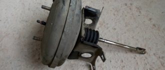
Vacuum brake booster device
Structurally, the vacuum amplifier is a sealed round-shaped housing. It is installed in front of the brake pedal in the engine compartment. The main brake cylinder is located on its body. There is another type of device - a hydraulic vacuum brake booster, which is included in the hydraulic part of the drive.
Brake booster circuit diagram
The vacuum brake booster consists of the following elements:
- frame;
- aperture (for two cameras);
- follow-up valve;
- brake pedal pusher;
- brake hydraulic cylinder piston rod;
- return spring.
The body of the device is divided by a diaphragm into two chambers: vacuum and atmospheric. The first is located on the side of the main brake cylinder, the second on the brake pedal side. Through the check valve of the amplifier, the vacuum chamber is connected to a source of vacuum (vacuum), which on cars with a gasoline engine is used by the intake manifold before supplying fuel to the cylinders.
Vacuum pump
In a diesel engine, the source of vacuum is an electric vacuum pump. Here the vacuum in the intake manifold is insignificant, so the pump is a mandatory element. The check valve of the vacuum brake booster disconnects it from the source of vacuum when the engine is stopped, as well as in cases in which the electric vacuum pump fails.
The diaphragm is connected to the piston rod of the main brake cylinder from the vacuum chamber side. Its movement ensures the movement of the piston and the injection of brake fluid to the wheel cylinders.
The atmospheric chamber in the initial position is connected to the vacuum chamber, and when the brake pedal is pressed, it is connected to the atmosphere. Communication with the atmosphere is provided by a follower valve, the movement of which occurs using a pusher.
In order to increase the braking efficiency in an emergency, the vacuum brake design can include an emergency braking system in the form of an additional electromagnetic rod drive.
The brakes stopped working
In the worst case scenario, the brake booster control valve fails completely, resulting in complete inoperability of the brake system. Fortunately, such an outcome is unlikely. But if suddenly it does occur, carefully stop the car, tow it home and contact a qualified specialist in the diagnosis and repair of brake systems. Depending on the severity of the case, the matter may be limited to only replacing the valve, but serious repairs of the entire brake system may be required.
The brake booster control valve is an important element of the braking system, ensuring driving safety. That is why the presence of the described symptoms should not be ignored or postponed “for later”. Contact a qualified mechanic who can professionally diagnose and repair your vehicle's brake system.
The design of the brake system of any car must include a booster. The most widely used in transport is the vacuum type amplifier, which provides additional force due to vacuum.
Operating principle of a vacuum brake booster
The vacuum brake booster operates due to different pressures in the chambers. In this case, in the initial position, the pressure in both chambers will be the same and equal to the pressure created by the vacuum source.
When you press the brake pedal, the pusher transmits force to the follower valve, which closes the channel connecting both chambers. Further movement of the valve facilitates the connection of the atmospheric chamber through a connecting channel with the atmosphere. As a result, the vacuum in the chamber decreases. The pressure difference in the chambers moves the piston rod of the master cylinder. When the braking ends, the chambers are reconnected and the pressure in them is equalized. The diaphragm, under the action of the return spring, takes its original position. The vacuum cleaner works proportionally to the force of pressing the brake pedal, i.e. The harder the driver presses the brake pedal, the more efficiently the device will work.
Stiff brake pedal
When the brake booster control valve is working correctly, the brake pedal is pressed easily and smoothly. If the valve malfunctions, controlling the brake pedal becomes noticeably more difficult. Instead of being soft and light, the pedal becomes hard and tight. It is very difficult to press. This is due to increased pressure in the master cylinder, which the control valve is designed to regulate. Abnormalities in the brake pedal operation are a sign of possible brake malfunction and indicate the need for immediate diagnostics of the brake system.
Best driving instructors:
Automotive instructor Svetlana Automatic transmission: Hyundai AccentTeaches in Northern Administrative Okrug, North-Western Administrative Okrug, Khimki REVIEWS
Driving instructor Elena Automatic transmission: Chevrolet Lacetti Manual transmission: Chevrolet LanosTeaches in the Southern Administrative District, South-Eastern Administrative District, Vidnoye, Domodedovo REVIEWS
Driving instructor Marina Automatic transmission: Kia Cerato Manual transmission: Chevrolet LanosTeaches in the Northern Administrative Okrug, Dolgoprudny REVIEWS
Driving instructor Elena Automatic transmission: Kia Cerato Manual transmission: Chevrolet LanosTrains in the Northern Administrative Okrug, North-Western Administrative Okrug, Khimki REVIEWS
Driving instructor Natalya Automatic transmission: Kia Spectra Teaches in the Eastern Administrative District, Balashikha, Reutov REVIEWS
Driving instructor Oleg Automatic transmission: Chevrolet Lacetti Manual transmission: Chevrolet LanosTeaches in the Northern Administrative District, Dolgoprudny REVIEWS
Driving instructor Yana Automatic transmission: Kia Spectra Teaches in the Northern Administrative Okrug, Dolgoprudny REVIEWS
Driving instructor Yulia Automatic transmission: Chevrolet Lacetti Manual transmission: Chevrolet LanosTrains in the Eastern Administrative District, South-Eastern Administrative District, Lyubertsy, Reutov, Zheleznodorozhny REVIEWS
Automotive instructor Svetlana Automatic transmission: Chevrolet Lacetti Trains at Northwestern Administrative Okrug REVIEWS
Driving instructor Tatyana Manual transmission: Chevrolet Lanos Automatic transmission: Kia SpectraTeaches in Krasnogorsk REVIEWS
Driving instructor Peter Manual: Daewoo Nexia Trains at Northwestern Administrative Okrug REVIEWS
Automotive instructor Oksana Automatic transmission: Hyundai Accent Teaches in North-Eastern Administrative District, Mytishchi, Korolev, Pushkin REVIEWS
Driving instructor Dmitry Automatic transmission: Volkswagen Golf Manual transmission: Chevrolet Lanos Trains in North-East Administrative District, Northern Administrative District, North-Western Administrative District, Dolgoprudny REVIEWS
Driving instructor Oksana Automatic transmission: Kia Spectra Manual transmission: Chevrolet Lanos Trains in the Southern Administrative District, South-Western Administrative District, Vidnoye, Podolsk REVIEWS
Automotive instructor Dmitry Manual transmission: Lada Granta Teaches in the South-East Administrative District, Lyubertsy REVIEWS