In our short article we will talk about the VAZ-2110 fuel system (injector). Carburetor engines have long gone into oblivion. The manufacturer has not installed such motors since the early 2000s. Most of the “ten” and similar models (2112, 2111) are equipped with engines with a fuel injection system. It is more reliable, works stably, and most importantly, does not require frequent intervention from the driver. The engine will be able to operate without problems, but provided, of course, that all filters are changed in a timely manner. There is also a requirement for fuel - it is not recommended to use low-quality fuel.
Basic moments
The fuel system of the VAZ-2110 (8 valves or 16) includes a fairly large number of elements that affect the operation of the engine. It is also worth mentioning that a mixture of gasoline and air is supplied to the combustion chambers of any engine in a certain proportion (more precisely, 14 parts of air and 1 gasoline).
If this ratio is violated, the engine will start to work incorrectly - the speed will decrease or increase, and interruptions will appear.
Principle of operation
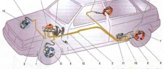
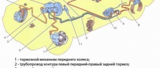
The “ten” type of braking system, namely a hydraulic dual-circuit with diagonal distribution, works well and can be considered quite reliable. A simple but successful brake system project, which is not always liked by car owners. Although few people take into account the fact that if one circuit decides to stop fulfilling its direct purpose, then the second will give the opportunity to slow down in a timely manner. Both circuits can fail only if there is a global oversight of the technical condition of the “chervonets”.
Reference. The design of the circuit system looks like this: from front left to rear right and vice versa. A kind of “X” of the brake system from the manufacturer.
This type of brake arrangement helps prevent you from going into a strong roll, skidding, turning 360 degrees around one side, or even turning over when braking with one of the available circuits.
Design Features
The fuel system design includes the following components:
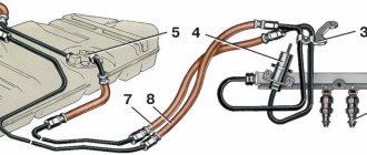
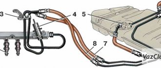
- The fuel supply system itself consists of a gas tank, a pump, a pressure regulator, gasoline filters, a ramp and injectors, as well as connecting tubes and hoses. In other words, these are the elements in which gasoline is found.
- The air supply system is those elements that allow oxygen to pass through. This is an air purification filter, a pipe, a throttle assembly, and a flow sensor. It is with the help of these elements that purified air is supplied to the fuel rail to form a mixture.
- And the last system allows you to catch gasoline vapors. This is an adsorber and connecting tubes. With their help, couples are destroyed.
The fuel supply system is needed to ensure the presence of the required amount of mixture in the ramp when operating in any mode.
Damage diagnostics
How to understand that an injector needs to be replaced, checked or repaired? Even without sensors, you can understand that repair of fuel system elements is required if there are 1 of 2 main signs in models 2107, 21074:
- Unstable engine operation. Sometimes it may stall or have difficulty starting.
- A much less obvious sign is loss of power. This effect is noticeable if you mostly drive at medium speeds, but at high speeds it is very noticeable.
- The last sign is recorded only by sensors - the pressure inside the system increases.
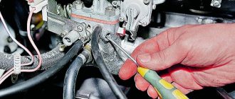
The cause of such failures is clogged injectors; even diagnostics are not needed. Cleaning helps restore the engine to its original performance. If the problem has not been resolved after cleaning, it is worth checking the tubes and injectors for damage or breakdowns. In such cases, it is better not to start repairs, but simply replace the damaged parts with new ones.
Sometimes it is impossible to determine on your own where the damage is, and only then will diagnostics at service centers come in handy. A blockage can cause quite serious damage to the VAZ 2107 injector, as well as rupture of channels. The pressure that arises inside the system can easily destroy the most fragile parts. Here you won’t be able to fix the situation with your own hands, even if you have a complete diagram of the car at hand. There is only one conclusion - you need to devote a lot of time and attention to cleaning injectors and do it regularly.
Differences in power systems
It is worth noting that the power supply systems for the VAZ-2111 and VAZ-2112 engines are slightly different from the VAZ-21114 and VAZ-21124. The last two do not have a return line through which gasoline returns to the tank. The reason is that the fuel pressure regulator is located in the same module as the fuel pump, in the tank. Therefore, it is possible to control the pressure in the system at an early stage, so to speak. And in this case, there is no need to lay a return line.
In addition, in order to connect various components of the line, the VAZ-21114 and VAZ-21124 engines use clamp-type tips, rather than threaded fittings. There are also differences in the shape and design of the ramp; newer injectors are installed on it. And most importantly, the pressure in the system is slightly higher than on earlier engine models.
Modifications of VAZ-2111
- VAZ-21111 with an opening rear door, station wagon with a 1.5-liter carburetor engine.
- VAZ-21110 is equipped with an injection 8-valve engine with a working volume of 1.5 liters.
- VAZ-21112 station wagon with an injection 8-valve engine with a volume of 1.6 liters and a power of 80 hp. With.
- VAZ-21113 with a 16-valve injection engine with a volume of 1.5 liters.
- VAZ-21114 with a 16-valve injection engine 1.6 liters 89 horsepower.
- VAZ-21116 - 04 all-wheel drive station wagon equipped with a 2-liter Opel C20XE engine with a capacity of 150 horses. It featured enlarged wheel arch cutouts, a redesigned bumper skirt with integrated fog lights and an updated aerodynamic shield over the rear.
- VAZ-2111-90 "Tarzan-2" all-wheel drive station wagon built on the basis of the VAZ-2111, produced since 1999. Like the previous generation of Tarzans, the body of the VAZ-2111 car was placed on a frame from the Niva, the rear suspension of the car was independent.
Air intake and throttle valve
The first thing we will consider from the design of the VAZ-2110 fuel system (injector, 8 valves) is the air supply. An air purification filter is installed at the inlet - on the “tens” it is made of paper, flat, and has a large surface area. Due to this, filtration occurs as efficiently as possible. The design of the throttle assembly looks like this:
- The pipe through which liquid from the cooling system is supplied to the housing.
- The pipe through which the crankcase is ventilated during idle operation.
- A pipe through which liquid is drained.
- A sensor that allows you to determine the position of the damper when the engine is running.
- Idle air control (you can’t call it a sensor, since the device doesn’t measure anything). This is a simple stepper electric motor that allows you to change the amount of air supplied to the ramp when idling.
- Fitting – necessary for purging the adsorber.
Caliper device
Let's move on. The front axle mechanisms are disk ones, consisting of calipers with the main brake elements - pads, and brake discs.
A caliper is a body with cylinders made in it for the pistons. This model has two of them, one for each block. The support structure is shown in the figure.
The caliper pistons have the form of a glass, which is placed in their cylinders, but they can move along it. To prevent fluid leakage, the pistons are equipped with o-rings.
Pads are small metal plates onto which linings made of friction material are glued.
The brake disc is made of metal for better adhesion to the surface of the pads; its side surfaces are well processed so that there are no protrusions or shells on them.
The VAZ 2107 brakes work like this: the fluid moves into the caliper cylinders, where it begins to push out the pistons. They come out of the cylinders, pressing the pads against the disc.
Throttle design features
The throttle assembly is attached directly to the receiver. With its help, air is dosed, which enters the intake pipe. A throttle assembly is installed between the inlet pipe (with filter) and the ramp. The damper is connected to the gas pedal via a cable. A sensor is installed on the damper itself; it allows the electronic control unit to determine the position of the damper when the engine is running.
It is worth noting that the fuel system of the VAZ-2110 (16 valves) is approximately the same in design as that of an eight-valve engine. In the flow part of the throttle assembly (immediately before the valve and immediately after it) there are holes that allow vacuum to be removed. With their help, the system responsible for ventilation of the adsorber and crankcase operates. If an adsorber is not installed on the car, the fitting required for purging is closed with a rubber plug. On VAZ-21114 and VAZ-211124 engines there is no channel through which air is supplied to bypass the damper. The connecting flange also has a slightly different shape.
Electrical equipment
Electrical equipment of VAZ
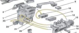
The car is provided with electrical energy by a generator. VAZ 2199 cars are equipped with an alternating current generator. The main requirements that the generator must fulfill are as follows: the generator provides an uninterrupted supply of current and has sufficient power. To operate effectively, a generator must be durable, have a significant resource, and at the same time its weight and dimensions must be small. It is also desirable that the generator have a low level of noise and radio interference. The generator operates on the principle of electromagnetic induction.
Fuses are very important in the electrical equipment of a car. Often, a car not running can be resolved by replacing the fuses. You can find out how the fuses are located in your car in the diagram in the instructions.
The wiring to the Solex carburetor is distinguished by the presence of additional sensors and a different arrangement of indicators.
Idle speed adjustment
On carburetor engines, cold starting was quite difficult - it was necessary to pull the “choke” cable so that more gasoline and less air entered the combustion chambers. And it was necessary to open the air supply in a timely manner, otherwise the car would “eat” gasoline very greedily. As for adjusting the idle speed on injection engines, a specially designed engine (IAC) is used for this.
When the valve is closed, air enters the fuel rail through a thin channel, bypassing it. This channel is closed by a conical needle, which is mounted on the regulator. The microcontroller control system, depending on the engine operating mode, sends a signal to the electric motor. At the same time, the needle moves, changing the air supply to the ramp. At the same time, a certain engine speed is maintained - specifically, 750 rpm.
Gasoline pump and purification
Using a two-stage electric drive, the fuel pump pumps gasoline into the line. The pump is of a rotary type, it is not dismountable, and is installed directly in the gas tank. This reduces the possibility of a vapor lock occurring, since gasoline is injected under high pressure and not under vacuum. The pressure value is about 284 kPa on VAZ-2111 and VAZ-2112 engines, and also over 364 kPa on VAZ-21114 and VAZ-21124 engine models.
The gasoline filter is built into the supply line directly between the ramp and the electric pump. It is located under the body, directly next to the fuel tank. The filter is a non-separable element; the housing is made of steel. Inside there is a paper type filter element. For rough cleaning of fuel, a so-called diaper is used, which is installed in the lower part of the pump.
Brake master cylinder
The master cylinder is connected to the booster. This element is a housing to which the supply and return pipelines from the fluid reservoir are connected, and 3 pipelines leading to the brake mechanisms exit. There is one pipeline leading to the front brake mechanisms, and only one to the rear, leading to the regulator.
Inside this housing there are pistons that push the liquid into the pipelines. One of them is connected to the amplifier diaphragm rod. These are the main elements of the drive. The detailed design of the brake master cylinder is shown above.
Related link:
Causes of detonation of VAZ engines and solutions
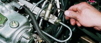
Ramps and injectors
The ramp is a hollow bar with nozzles installed on it and a specially designed mixture pressure regulator. The ramp is mounted with two bolts on the intake pipe or directly on the cylinder head. On the left side there is a fitting with which the fuel pressure is monitored (during diagnostics). It is closed with a threaded plug.
The injectors are fixed to the ramp. The injector nozzles are located in the intake manifold openings. But on the VAZ-2112 and VAZ-21124 engine models, the injectors are installed in the holes on the cylinder head. In order to seal the mounting holes of the electromagnetic injectors, rubber rings are installed. An injector is a regular valve with an electromagnet.
When a pulse is received from the microcontroller, the valve opens for a certain time. In this case, the fuel mixture is supplied through a sprayer into the combustion chamber through a valve. The fuel begins to evaporate, comes into contact with hot elements, and in a state of steam ignites in the combustion chamber. Ignition occurs with the help of a spark plug. As soon as the pulse to the injector stops, the valve returns to its original position using a return spring.
Fuel pressure adjustment
How is pressure maintained in the fuel system of the VAZ-2110? On cars with VAZ-2111 and VAZ-2112 engines, a pressure regulator is installed directly on the fuel rail. With its help, a certain pressure value is maintained inside. Moreover, it allows you to maintain both air pressure in the intake pipe and fuel inside the ramp.
The design of the regulator is not very complicated. Inside it are a valve, a diaphragm and a return spring. When the engine is running, the regulator allows you to maintain pressure in the range of 284-325 kPa. On the one hand, the diaphragm of the device is affected by fuel, and on the other, by low pressure in the intake pipe. As soon as the pressure in the intake manifold decreases, the valve begins to open. In this case, excess fuel is passed into the drain line to the tank. The pressure in the ramp is significantly reduced.
As soon as the pressure in the intake manifold increases (this happens when the damper opens), the valve on the regulator begins to open at a significantly higher pressure of the fuel mixture. At the same time, the fuel pressure inside the ramp increases significantly.
But on VAZ-2114 and VAZ-21124 engines, the pressure regulator is placed inside the module, next to the fuel pump. This is a kind of check valve in the fuel system of the VAZ-2110, which operates at a certain pressure (about 400 kPa). If the pressure exceeds the norm, the drain line opens and excess fuel is returned back to the tank.
Vacuum brake booster
A rod connected to the amplifier is connected to the pedal. The design of the VAZ-2107 vacuum brake booster is quite interesting; it is shown in the figure:
The amplifier is a sealed container, internally divided into 2 chambers by means of a membrane. The chamber located closer to the pedal is called atmospheric, and the chamber separated from it by a membrane is called vacuum. The diaphragm itself is connected to the piston rod of the master cylinder.
The vacuum chamber is connected by a pipe to the intake manifold of the engine, where the vacuum comes from. The design also includes a follower valve controlled by the pedal rod, which does all the work.
When the pedal is released, this valve connects the chamber cavities through a channel, providing identical pressure. When the pedal is applied, the valve closes the channel connecting the chambers and opens the channel connecting the atmospheric chamber with the atmosphere. Since a vacuum is maintained in the second chamber, atmospheric pressure begins to put pressure on the membrane. Since it is connected to the piston rod of the master cylinder, due to the movement of the piston, fluid is displaced from the cylinder into the pipelines.