The mass air flow sensor is a special sensor that monitors the mass air flow of the power plant. Where is this control device located? In the fuel system of the engine, or rather, directly in the intake tract. Experts call it the most important element that ensures proper fuel injection into the engine. This sensor, like any other component, can fail.
This article describes how the mass air flow sensor operates on the VAZ-2115 and the possible problems that arise when it fails. We will also tell you about ways to eliminate them.
The principle of operation of the DMRV sensor VAZ 2114, 2113, 2115
DMRV 2114, 2113, 2115 (hot-wire sample) contains a sensing part, a thin mesh (diaphragm) based on silicon, placed in the flow of incoming air. On the grid there is a heated resistor and two thermal sensors located in front of the heated resistor and after it.
The operating principle of the DMRV consists of different readings from two temperature sensors, one of which is located in front of the heating resistor, and three behind it. The heating resistor itself is located on a thin mesh (membrane) based on silicon, mounted in the flow of air passing through the air flow sensor of the VAZ 2114, 2113, 2115 hatchback model 21083-1130010. While the engine is running, the passing air flow cools the part of the mesh located in front of the heating resistor. This causes the heating sensor located in front of the heating resistor to cool down. And the temperature sensor located behind the heating resistor remains warm due to the heated air flow. The differential pulse of these two temperature sensors makes it possible to develop a characteristic curve depending on the size of the air passed through the mass air flow sensor. The pulse created by the air measurement sensor is analog. The MAF signal is a direct current voltage varying in the range from 1 to 5 V. Its size depends on the amount of air passing through it. The ECU, having received a signal from the DMRV VAZ 2114, 2113, 2115, model .21083-1130010, using its data tables, calculates the duration of the opening time of the fuel injectors. The duration of the fuel injector opening pulse corresponds to the parameters of high air consumption
Important ! Various diagrams of the VAZ 2114 car
Operating principle of the air flow sensor
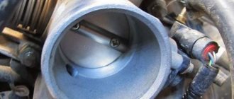
The sensor is based on a platinum wire only 70 micrometers thick. It is hidden in a special tube located in front of the throttle valve. When air hits it, the wire cools. To restore normal temperature, a certain charge of electricity passes through it, according to the size of its ECU, and finds out exactly how much fuel the engine needs at the moment.
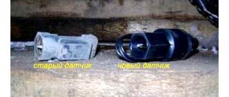
Due to the fact that air comes directly from the atmosphere, dirt regularly settles on the wire. It is this that, for the most part, contributes to the fact that the sensor becomes unusable. The latest models of mass air flow sensors, however, have an automatic cleaning system.
A significant drawback of the described design is its inability to repair. As a result, sooner or later, the expense of money becomes inevitable.
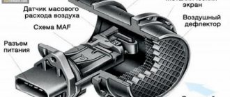
Mass air flow sensor design
| Position number | Explanation of the position in the figure DMRV VAZ 2114, 2113, 2115 |
| 1 | Frame |
| 2 | Connector |
| 3 | DMRV VAZ 2114, 2113, 2115 |
| 4 | MAF circuit |
| 5 | Metal screen |
| 6 | Air deflector |
| 7 | Inlet air flow |
Technical characteristics of DMRV VAZ 2114, 2113, 2115 models 21083-1130010-01
DMRV 2114, 2113, 2115 model 21083-1130010-01 has the following technical characteristics:
- Measuring range of mass air flow - from 8 to 550 kg/h;
- The error in measuring the air flow of the new VAZ 2114 air flow sensor is +/- 2.5%;
- The magnitude of the output signal when measuring the flow range from 0 to 100% is from 0.05 to 5 V;
- The sensor is powered from the vehicle's on-board network with a rated voltage of 12 V;
- The supply voltage range is from 7.5 to 16 V;
- Current consumption (at supply voltage from 7.5 to 16 V) - 0.5 A;
- Operating temperature range - from -45 degrees. up to +120 degrees. WITH;
- MTBF, no less than 3000 hours;
- Weight (gross): 0.3 kg;
- Overall dimensions of the package: 135x125x113 mm.
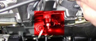
Replacement
Replacing the sensor is quite simple; all you need is a 10 mm wrench and a Phillips screwdriver.
- Remove the connector from the sensor;
- Loosen the clamp securing the corrugation to the sensor;
- Unscrew the two bolts using a 10 mm wrench;
- Remove the sensor;
- We assemble in the reverse order;
The replacement process is complete, after this procedure your car should drive like new.
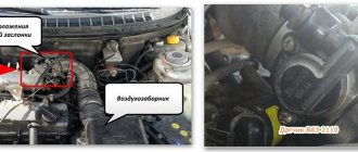
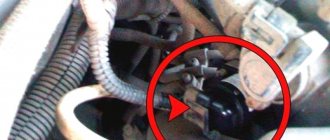
Installation location of mass air flow sensor on VAZ 2114, 2113, 2115
DMRV VAZ 2114, 2113, 2115 8 valves are attached to the air filter housing, on the one hand, and to a flexible rubber pipe, on the other hand. It is located between the atmospheric filter and the throttling device,
| Item no. | Explanation of the position on the diagram |
| 1 | crankshaft sensor mounting point (in the cylinder block boss) |
| 2 | sprayers |
| 3 | throttle body and freewheel regulator (located on the air damper body) |
| 4 | dprv |
| 5 | DMRV VAZ 2114, 2113, 2115 |
| 6 | canister venting valve |
| 7 | dtozh |
| 8 | ignition module (salenoid) |
| 9 | spark plugs with caps of high-voltage wires put on them |
| 10 | dd |
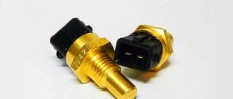
Important ! Coolant temperature sensor VAZ 2114, 2113, 2115 model 2112-3851010 It, like the crankshaft sensor, greatly influences the start and operation of the engine of the VAZ 2114, 2113, 2115
Causes of malfunctions
In 90% of cases, this is contamination of sensitive sensors.
- a low-quality (not certified) or incorrectly installed air filter allows dust to enter the mass air flow sensor measuring channel;
- when operating the vehicle in wet weather or driving through puddles, droplets of water may enter the intake manifold;
- If the crankcase ventilation system does not work (damaged hoses, broken valve), drops of oil enter the air duct pipe.
A dirty sensor can be cleaned or even washed.
Important! Mechanical impact (brushes, cotton swabs) and the use of aggressive agents (acetone, gasoline) are not allowed.
For small amounts of dirt, blowing with compressed air is sufficient. If the air attack does not help, use a special aerosol cleaner for carburetors and mass air flow sensors.
Before reinstallation, the flowmeter must be allowed to dry in the open air.
DMRV connection diagrams VAZ 2114, 2113, 2115 8 valves
Depending on the model of the installed DMRV controller of the VAZ 2114, 2113, 2115, 8 valves have various connection options:
- 1. Connection diagram for air flow sensor with ECU BOSCH M1.5.4, M1.5.4N, January 5.1, 5.1.1, 5.1.2, VS 5.1 (* - for distributed fuel dosing modes with ECU 2111-1411020-60, -61,- 62 instead of terminal “30” of the ECU, terminal “48” is used).
- Terminal “1” is empty;
- Terminal “3” - to contact 30(48) of the controller;
- Contact “4” - to terminal 12 of the ECU;
- Terminal “5” - to pin 7 of the controller.
Contact “2” - to the main relay and speed sensor;
- Pin “1” - to pin 44 of the ECU;
Contact “2” - to the main relay and speed sensor;
Examination
The check is carried out in 2 stages: the first is a visual inspection, the second is a test using a device (multimeter or computer diagnostics). Let's consider each of the options in more detail.
First stage (visual inspection)
To do this, you need to remove the mass air flow sensor and inspect it.
The inspection includes checking:
- Integrity of contacts on the connector;
- Cleanliness inside the sensor;
- Integrity of the sensing element inside the sensor;
- No cracks or chips on the body;
If no damage is found, you can proceed to the second stage of the inspection.
Second stage (test with device)
To test the device, you can use computer diagnostics or a multimeter. In most cases, the ELM327 scanner and the OpenDiag program help to diagnose the sensor; you just need to install this program on your smartphone and connect to the scanner via Bluetooth, after which you can check the status of the sensor using the ADC channels.
The test can also be carried out using a multimeter, as this is described in detail in the video.
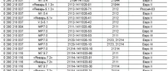
Applicability of the mass air flow sensor depending on the controller
| Table of application of various models of mass flow sensor 2114, 2113, 2115 depending on the brand of controller | ||||||||||||
| the name of detail | Model DMRV VAZ 2114, 2113, 2115 | Controller name | ||||||||||
| G.M. | January 4.1 | M 1.5.4 | MP7.0N | M1.5.4, I 5.1.1, I 5.1.2, VS 5.1 | M 1.5.4N, I 5.1, VS 5.1 | MP 7.0N, EURO 3 | ||||||
| 8th grade | 8 classes | 16th grade | 8 classes | 8 classes | 8 classes | 16th grade | 8 classes | 16th grade | 8th grade | 16th grade | ||
| DMRV 2114, 2113, 2115 | ||||||||||||
| 2112-1130010 2112-1130010-01* | + | + | + | — | — | — | — | — | — | — | — | |
| 21083-1130010-01 | — | — | — | + | — | — | — | — | — | — | — | |
| 21083-1130010-10 | — | — | — | — | + | + | + | + | + | + | + | |
Note: * - products manufactured by GM; the arrangement of two or more numbers on one line indicates their interchangeability.
Important ! Tightening torques for VAZ 2114
DMRV pinout for VAZ 2114, 2113, 2115
The VAZ 2111 (l.5i) and VAZ 11183 (l.6i) engines were installed on VAZ 2114, 2113, 2115 cars. These motors have different methods of connecting the air flow sensor and therefore have slightly different wiring. The pinout options for the mass air flow sensor are presented below.
Pinout of MAF VAZ 2114, 2113, 2115 for VAZ 11183 (l.6i) engine:
- — temperature sensor signal;
- — + 12 V;
- - weight;
- — + 5 V
- - DMRV signal.
Pinout of MAF VAZ 2114, 2113, 2115 for VAZ 2111 (l.5i) engine:
- — ;
- — + 12 V;
- - weight;
- — + 5 V
- - DMRV signal.
Malfunctions of the MAF sensor VAZ 2114, 2113, 2115
| Symptom of malfunction of VAZ 2114, 2113, 2115 DMRV on the engine | Fault signal | Remedy |
| The engine runs rough or stalls at idle | The "Check Engine" light comes on. The malfunction is typical for a frequency type sensor (System with a GM or January-4 controller). The "Check Engine" light may not be on. | Replace the faulty air sensor. You can get to the repair site by disconnecting the connector from the sensor (in this case, the engine speed will increase to approximately 2000 rpm |
| High idle speed | The "Check Engine" light comes on. Check the sensors and circuits with an autotester. | Replace the faulty sensor. Ensure contact in electrical circuits.. |
| The engine does not develop full power and does not have sufficient throttle response. Jerks and dips when the car is moving. | Typically the check engine light is on. If there is a break in the circuit or air flow sensor, the engine speed does not drop below 2000 min-1. The car accelerates poorly when you press the gas pedal. | Restore contact in electrical circuits. Replace the faulty mass air flow sensor 2114, 2113, 2115. |
| Increased fuel consumption | Typically the check engine light is on. If there is a break in the circuit or air flow sensor, the engine speed does not drop below 2000 min-1. The car accelerates poorly when the gas pedal is pressed. | Restore contact in electrical circuits. Replace the faulty air meter. |
| Increased content of harmful substances in exhaust gases | Typically the check engine light is on. If there is a break in the circuit or air flow sensor, the engine speed does not drop below 2000 min-1. The car accelerates poorly when you press the gas pedal. | Restore contact in electrical circuits. Replace the faulty air sensor. |
Checking and repairing at home
There are eight ways to independently check amplitude and frequency mass flow sensors.
Method No. 1 - disabling the air flow meter
The method consists of disconnecting the sensor from the fuel system of the car and checking the functionality of the system without it. To do this, you need to disconnect the device from the connector and start the engine. Without a mass air flow sensor, the controller receives a signal to switch to emergency operation mode. It prepares the air-fuel mixture only based on the throttle position. If the car moves faster and does not stall, it means that the device is faulty and requires repair or replacement.
Method No. 2 - flashing the electronic control unit
If the standard firmware has been changed, then it is unknown what reaction of the controller is programmed in it in case of an emergency. In this case, you should try to insert a 1mm thick plate under the throttle stop. The turnover should increase. Now you need to pull out the chip from the air flow meter. If the power unit continues to work, then the cause of the malfunction is the firmware.
Method No. 3 - installing a working sensor
Install a known good part and start the engine. If after replacement it begins to work better, the motor does not stall, then replacement or repair of the device is required.
Method No. 4 - visual inspection
To do this, use a Phillips screwdriver to unscrew the clamp holding the air collector corrugation. Then you need to disconnect the corrugation and inspect the internal surfaces of the air collector corrugation and the sensor.
Inspection of duct corrugation
There should be no traces of oil or condensation on them, the surfaces should be dry and clean. If you do not take care of the air filter and change it rarely, then dirt can get on the sensitive element of the sensor and cause it to break. This is the most common malfunction. Traces of oil may appear in the flow meter if the oil level in the crankcase is high, or if the oil sump of the crankcase ventilation system is clogged. If necessary, you need to clean the surfaces using special cleaning products.
Method No. 5 - checking the mass air flow sensor with a multimeter
To do this, you need to turn on the tester in a mode in which constant voltage is checked. The limit value for measurements should be set to 2V.
DMRV operation diagram
Sensor pinout:
- The yellow wire is located closer to the windshield. It serves as an input for a signal from the flow meter.
- The white-gray wire is the sensor voltage output.
- The black and pink wire leads to the main relay.
- The green wire is used to ground the sensors, that is, it goes to ground.
The wires may have different colors, but their location is unchanged. To check, you need to turn on the ignition, but do not start the car. The red probe from the multimeter must be connected to the yellow wire, and the black one must be connected to ground, that is, to the green wire. We measure the voltage between these two outputs. Multimeter probes make it possible to connect without disturbing the insulation of the wires.
On the new device, the output voltage ranges from 0.996 to 1.01 V.
During operation, this voltage gradually increases and by its value one can judge the wear of the flow meter:
- if the sensor is in good condition, the voltage is from 1.01 to 1.02 V;
- in satisfactory condition - from 1.02 to 1.03 V;
- the sensor resource ends if the voltage is in the range from 1.03 to 1.04 V;
- a value in the range from 1.04 to 1.05 indicates a near-death state; if there are no contraindications, then you can continue to use the sensor;
- if the voltage exceeds 1.05 V, the mass air flow sensor requires replacement.
ADC flow meter readings
Diagnostics of the mass air flow sensor "Tseshkoy" is not difficult and can be done with your own hands.
If there is dirt on the removed sensor, you can clean it yourself. You can use WD-40 to wash it. To clean the mass air flow sensor, you must first remove the pipe from it, and then dismantle the device itself. Inside the device there is a mesh and several wires - sensors.
They need to be sprayed with cleaning agent and washed. Then let the liquid dry. If dirt remains, the procedure should be repeated. You need to clean the pipe with the same product. It must be free of dirt and oil stains. After replacing the air filter, all parts must be returned to their place. After the cleaning procedure, the functionality of the device can be restored to 80%, the error about the reduced sensor signal level disappears (the author of the video is “24 hours”).
Flushing the sensor will help avoid costly repairs.
Method number 6 - checking with a scanner
Test method:
- Install a diagnostic program on your phone (smartphone), tablet or laptop computer (for example, Torque Pro, Opendiag, BMWhat, OBD Auto Doctor).
- Connect your mobile device or laptop to the diagnostic connector located on the vehicle's electronic control unit using a special cable, Bluetooth channel.
- Launch the diagnostic utility on your phone (smartphone) or computer.
- Wait until the program finishes scanning all vehicle components. As a result, the utility will check the serviceability of each vehicle unit.
- Decipher the error codes that the program will show after the diagnostics are completed.
To perform this method, testers are used:
- K-Line 409/1;
- Scanmatic;
- ELM (ELM) 327;
- OP-COM.
Method No. 7 - checking by Vasya the Diagnosticist
To identify a malfunction of the mass air flow sensor without removing it from the car, you need to:
- Install a program called “VASYA diagnostician” on your laptop (laptop) and run it.
- Connect the adapter to the vehicle's diagnostic port.
- Select the item “Electronics 1” or “01 – Engine electronics” from the “Control unit” tabs to connect to the vehicle’s control unit.
- Go to “Custom Groups”.
- Select 211, 212 (passport value) and 213 (current value).
- Compare current indicators with passport data. If the deviations are high, then it is necessary to replace the mass air flow sensor.
Method No. 8 - using a motor tester
GOOD TO KNOW
This method is used to test frequency-type flowmeters.
To check the mass air flow sensor with a motor tester (oscilloscope), you need to connect it to the sensor (depending on the car brand) and start the engine.
Mass air flow sensor check parameters:
- transient time when the ignition is on;
- air consumption readings at idle and a sharp increase in engine speed;
- voltage in the sensor network.
IT IS IMPORTANT TO KNOW
The output data is individual for different types of engines. Before diagnosis, you should check the current indications with an official representative.
How to check DMRV 2114, 2113, 2115 8 valves with a multimeter?
Checking the mass air flow sensor model 21083-1130010 with a multimeter is carried out in the following sequence:
- Open the hood of the car;
- Press the lock with your finger and remove the terminal block from the air flow sensor of VAZ 2114, 2113, 2115 model 21083-1130010.
- Take a multimeter and switch it to voltmeter mode:
- We connect the negative probe of the multimeter to the motor housing (to ground);
- We turn on the ignition in the car and measure the voltage at terminal 2 of the wire harness with a multimeter (the numbering of the terminal terminals is marked on the air flow sensor VAZ 2114, 2113, 2115 8 valves model 21083-1130010) The voltage measured with a multimeter at terminal 2 must correspond to at least 12 V. When the voltage is not supplied to the terminal connector or it is less than 12 V, then the battery is discharged, the power line is broken or the ECU is broken.
- Using a multimeter, we measure the voltage at terminal 4 of the air meter connector, twist the wires. The voltage at terminal 4 should be about 5 V. When the voltage does not meet the standard, the sensor power line is damaged or the ECU is broken.
- We dismantle the air flow sensor VAZ 2114, 2113, 2115 8 valves and inspect it for mechanical damage. If mechanical damage to the sensitive elements is visible, then replace the MAF 2114, 2113, 2115 with a new one.
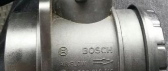
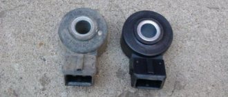
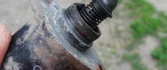
Design
The sensor is a cylindrical part made of special plastic that is resistant to high temperatures. The body of the sensor contains a special sensitive element that counts the amount of air entering the combustion chamber of the engine. A special mesh is installed in front of this element, which prevents the entry of large debris that can damage not only the sensor, but also the internal combustion engine itself.
The sensor has a connector for connecting a control circuit with 4 pins. The connector is connected to the sensor on one side, and on the other to the engine control unit.
VAZ 2114 car models
| Car model | Option code | Body type | Execution | Engine | Engine capacity | Toxicity standards | Controller |
| VAZ 2114-20 | 10 ->06.05 | Hatchback | Standard | 2111-86 | 1,5 | R83-02 | 2111-1411020-60 2111-1411020-61 2111-1411020-62 |
| 30 | Hatchback | Standard | 2111-80 | 1,5 | Euro-3 | 2111-1411020-80 2111-1411020-81 2111-1411020-82 | |
| 40 | Hatchback | Standard | 2111-75 | 1,5 | Euro 4 | 2111-1411020-30 | |
| 110 ->02.05 | Hatchback | Standard | 2111-86 | 1,5 | Euro 2 | 2111-1411020-40 | |
| 120 | Hatchback | Standard | 2111-80 | 1,5 | Euro-3 | 2111-1411020-80 2111-1411020-81 2111-1411020-82 | |
| VAZ 2114-21 | 10 ->06.05 | Hatchback | Norm | 2111-86 | 1,5 | R83-02 | 2111-1411020-60 2111-1411020-61 2111-1411020-62 |
| 30 | Hatchback | Norm | 2111-80 | 1,5 | Euro-3 | 2111-1411020-80 2111-1411020-81 2111-1411020-82 | |
| 40 | Hatchback | Norm | 2111-75 | 1,5 | Euro 4 | 2111-1411020-30 | |
| VAZ 2114-22 | 10 ->06.05 | Hatchback | Lux | 2111-86 | 1,5 | R83-02 | 2111-1411020-60 2111-1411020-61 2111-1411020-62 |
| 30 | Hatchback | Lux | 2111-80 | 1,5 | Euro-3 | 2111-1411020-80 2111-1411020-81 2111-1411020-82 | |
| 40 | Hatchback | Lux | 2111-75 | 1,5 | Euro 4 | 2111-1411020-30 | |
| VAZ 2114-22 | 110 ->02.05 | Hatchback | Lux | 2111-86 | 1,5 | Euro 2 | 2111-1411020-40 |
| 120 | Hatchback | Lux | 2111-80 | 1,5 | Euro-3 | 2111-1411020-80 2111-1411020-81 2111-1411020-82 | |
| VAZ 21144-20 | 10 | Hatchback | Standard | 11183-30 | 1.6 | Euro-3 | 21114-1411020-10 21114-1411020-11 |
| 20 | Hatchback | Standard | 11183-20 | 1,6 | Euro 2 | 21114-1411020-30 21114-1411020-31 21114-1411020-32 | |
| 110 | Hatchback | Standard | 11183-20 | 1,6 | Euro 2 | 21114-1411020-30 21114-1411020-31 21114-1411020-32 | |
| VAZ 21144-22 | 10 | Hatchback | Lux | 11183-30 | 1.6 | Euro-3 | 21114-1411020-10 21114-1411020-11 |
| 20 | Hatchback | Lux | 11183-20 | 1.6 | Euro 2 | 21114-1411020-30 21114-1411020-31 21114-1411020-32 | |
| 110 | Hatchback | Lux | 11183-20 | 1,6 | Euro 2 | 21114-1411020-30 21114-1411020-31 21114-1411020-32 |
Repair manuals and catalogs for the VAZ 2114 car
These manuals and catalogs can be downloaded and saved to your gadget.
- CATALOG OF PARTS AND ASSEMBLY UNITS VAZ 2114, 2113, 2115. —
- 266 pp.
- Size – 7,448 MB
- Format - pdf
- 2002
- 2002