On a modern car, several systems and a large number of sensors simultaneously monitor the operation of the engine and adjust its behavior when internal and external parameters change.
If any malfunctions or irregularities appear in the operation of the internal combustion engine, they are recorded by the control unit (ECU) and stored in memory. These errors may appear as lights on your dashboard. Most often we are talking about Check Engine.
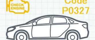
One of the errors that motorists may encounter when connecting to the ECU with a scanner is P0113. You should know what it means, what symptoms it is accompanied by and how to eliminate it on your own.
How does a mechanic diagnose a P0113 code?
When diagnosing this error, the mechanic will do the following:
- Reads all stored data and error codes using an OBD-II scanner to find out when and under what circumstances the P0113 error code appeared
- Clear error codes from the computer's memory and test drive the vehicle to see if P0113 appears again
- Visually inspect the intake air temperature sensor and associated electrical wires and connector
- Disconnect the intake air temperature sensor connector and observe the sensor readings in real time using a scanner. This will help determine if there is a short circuit inside the sensor or in the associated wires or connector
If no problem is found, the mechanic will continue diagnosing by following the vehicle manufacturer's procedure.
What does the error mean?
When the P0113 error occurs, the first thing that interests the motorist is its meaning.
Error P0113, stored in the ECU memory, indicates a failure on the part of the intake air temperature controller. Namely, a high signal level is observed.
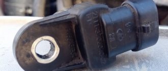
This is a sensor that monitors the temperature of the air entering directly into the engine for further formation of the air-fuel mixture.
Some vehicles use a separate sensor to perform these tasks. But most often it is an integral component of another controller. This could be an absolute pressure sensor or a mass air flow controller. Inside them there is a sensor that controls the pressure.
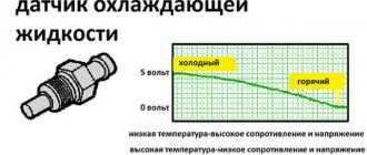
Structurally, the element is located in the air pipe. It's actually a thermistor. Depending on the temperature of the incoming air, the resistance of the controller changes. The control unit reacts to this and monitors the signals and behavior of the device. This allows:
- change the width of the pulse supplied to the engine injectors;
- change the ignition timing;
- influence the volume of supplied fuel;
- control stable idle speed, etc.
This sensor is also often called IAT (Intake Air Temperature).
The sensor parameters are most important at the moment the power unit starts. Working together with the coolant sensor, based on their resistance, the ECU receives accurate information and determines the optimal time for injection. This eliminates problems specifically during a hot start of the internal combustion engine.
If resistance data is transmitted incorrectly, error P0113 appears. If information is not transmitted at all, then error P0110 will pop up.
The error code in question indicates that the current incoming air density is higher than the maximum set level. That is, the temperature of the air that is sucked into the engine is low. This is usually due to a malfunction of the controller or its breakdown.
Symptoms
An error such as P0113 does not have pronounced and characteristic symptoms by which it could be accurately diagnosed. These are, rather, indirect signs that force the motorist to connect a scanner to the computer and read the errors in the memory.
You can suspect problems with the intake air temperature controller based on the following symptoms:
- the Check Engine light comes on on the dashboard;
- The ECU switches the engine to emergency or safe operating mode;
- fuel consumption indicators are increasing;
- If the car is all-wheel drive, the rear axle may spontaneously disengage.
If you continue to operate the car in such conditions, the wear of the valves and piston group increases. It is better to fix the problem as quickly as possible.
Yes, the symptoms discussed do not indicate that the intake air sensor has failed. But this is a reason to read the errors and look at their codes.
P0113 - engine intake air temperature sensor failure
If an error occurs, P0113 indicates an interruption in the operation of the sensor that controls the air intake temperature. In another way, when an error pops up, you can say for sure that the level of the signal coming from the IAT sensor, whose main task is to control the temperature regime of the inlet air, has been increased. In other engines this may be a separate sensor, but usually it is a regular sensor indicating absolute pressure.
The pop-up code P0113 signals a high temperature of the incoming air, nothing more than a thermistor.
The sensor is placed in the air duct pipe, the resulting resistance is associated with changes in temperature conditions, while the control unit helps to adjust the pulse width supplied to the injectors, this behavior entails an effect on the fuel, and also adjusts the ignition angle to advance, and also controls the idle speed. The indicators of the IAT sensor are considered very important; when starting the car, when interacting with the coolant sensor, the exact value of the injection time interval is determined, therefore it controls the engine starting when the engine is hot. If a problematic situation occurs with the inlet air temperature sensor, the resistance changes in direct proportion, so error P0113 occurs, called IAT, which can be identified during diagnostics. If the readings from the sensor are inconsistent, an error called P0110 is generated.
In what cases does error p0113 occur?
An error is generated in the EMC block, if the temperature drops below the minimum norm, in this case the incoming signal increases and leaves the maximum level, after which it lasts for 1-1.5 minutes. Next, the signal enters the memory located on the dashboard, after which the indication light turns on, but the shutdown will only occur in the case of 4 consecutive ignition processes, after which no malfunctions were detected. Clearing the memory of a fault will only occur after 40 consecutive ignition processes without detecting errors. In this case, after displaying code P0113 and then resetting it using a scanner or removing the terminals from the battery, the light will not simply stop lighting because the problem has not been resolved, so the speed will continue to jump.
Factors causing the occurrence of code p0113
Basically, the causes of occurrence are primarily related to the incoming air sensor:
- The contact in the power connectors has disappeared;
- IAT sensor wire is broken;
- Accumulated dirt;
- Damage to the incoming air temperature sensor itself. What to do to eliminate an error that occurs when the incoming air temperature changes.
First of all, when error P0013 pops up on the scanners, every car enthusiast first of all rushes to search for this sensor in order to replace it with a new one. But it is not entirely appropriate to immediately replace the sensor, because even after installing a new one, the error will not always disappear. Therefore, even if after changing the sensor the error continues to pop up, it’s tedious to look for another problem.
Follow these tips:
First of all, measure the resistance of the IAT sensor at different temperature readings, in which case you need to use a hair dryer or a container of warm water. To do this, make sure that the readings change proportionally, so it is not necessary to have a table with readings of the technical values of the sensors.
After this, we check the safety of the contacts and wiring of the sensor, because a rupture may have occurred or an oxidation process may have occurred.
To remove contaminants, it is worth using a carb cleaner, because accumulated quarry gases can contribute to the failure of the sensor.
Only after the above procedures can you resort to changing the air sensor itself, whether it is located in the flow meter or located on the intake manifold. Therefore, regardless of your brand of car, you should first use our recommendations and first check the DBP and start cleaning it, because buying a sensor can lead to loss of costs, and quite large ones.
DTV failure
Reasons for the release of DTVV:
- short circuit;
- contamination of the device;
- mechanical damage;
- oxidation or contamination of contacts or terminals;
- manufacturing defect.
Once a malfunction of the intake air temperature sensor has been diagnosed, it is necessary to dismantle and replace it.
Before changing the device, you should make sure that its malfunction is not caused by a simple accumulation of dirt, which is quite easy to remove with a rag moistened with an alcohol solution. In general, a breakdown, the cause of which may be corrosion of the contacts, is a fairly common occurrence. To avoid this, you should clean them of carbon deposits and dirt more often.
If these manipulations did not help and there are still errors in the operation of the detector, it should be replaced.
Conditions for generating an error
Such an error can only appear when certain conditions, a certain scenario, are met.
The error is recorded in the ECU when the engine starts. When starting the internal combustion engine, the ECU reads data from all sensors. If the air passing through the air duct has a density higher than the allowable value and this continues for more than 1.5 minutes, the check engine light will illuminate on the instrument panel.
If this is an accidental error, then after 4 normal starts the indicator on the instrument panel will go out. But the error itself will still be in the ECU memory. It is automatically erased only after 40 successful engine starts.
Repair instructions
When repairs are complete, perform Diagnostic Confirmation of Repairs Completed.
| • | Replacing the MAF Sensor/Intake Air Temperature Sensor to replace the MAF Sensor/Intake Air Temperature Sensor |
| • | To replace, program, and configure the engine control module, follow the Control Module Reference. |
How to eliminate an error in the incoming air temperature
Often, when car owners take readings from a car scanner, the display of which displays the code p0113, after receiving the decoding, they immediately look for the location of this sensor and rush to replace it with a new one. Although it is not always reasonable to do this, because there is no 100% certainty that error p0113 will go away after replacing the air pressure sensor or mass air flow sensor. Therefore, it often happens that I changed it, but the error does not go away - what should I do?
Tips for eliminating P0113 high signal level of the incoming air sensor are quite simple:
First you need to check the resistance of the IAT sensor at different air temperatures. This can be done using a hairdryer or a tank of warm water and a multimeter. Although the numerical ratio is different for each sensor model, it should always change proportionally. Therefore, even if you do not have a table with the technical characteristics of the sensor (°C/kOhm) at hand, it is important that the resistance changes proportionally with respect to temperature.
The next step is to check the contacts in the connector and the wiring of the sensor for air entering the engine (possibly oxidation or a break).
cleaning of the sensitive element with a carb cleaner can help eliminate error p0113 , since crankcase gases could heavily “clog” it with oil deposits.
And only if the above procedures did not help eliminate the problem, should you replace the air sensor , which, as a rule, is built into the flow meter or is a pressure sensor located on the intake manifold. Therefore, if error P0113 appears on your car, be it a VAZ, Ford, Audi or Subaru, then the first thing you should do is listen to the recommendations and start by checking the DBP and cleaning the sensor, since the price for some car models is quite steep.
Source
Checking the mass flow sensor with your own hands
In order to carry out the test, you must first ensure that the electrical wiring is in good condition. To do this, you can use a multimeter. The check is performed as follows:
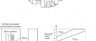
- The power supply cable in the VAZ 2114 has 5 contacts. They need to be numbered from 1 to 5.
- You need to measure the voltage between 2 and 3. It should be approximately 15 V. Between 3 and 4 the voltage should be 5 V.
- If you measure it between 3 and mass, then it should be equal to 0 .
- Now the multimeter is switched to measuring resistance. Between contact 5 and ground its value should be zero.
If the obtained values correspond to the expected ones, then the power supply wire is working, and the cause of the breakdown must be looked for elsewhere.
You need to check the operation of the thermal resistance. To do this, use a hairdryer or warm water. With their help you can change the temperature of the sensor. It is necessary to measure the resistance before and after heating. The readings must vary proportionately.
You need to inspect the sensor and make sure that there is no dirt on it that could distort the signal it transmits.
Scheme of work
How to recognize a detector malfunction?
The main signs of detector failure are the following:
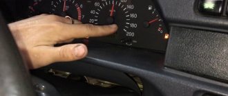
- difficulty starting the engine at low ambient temperatures;
- failures at idle speed;
- excessive fuel consumption;
- interruptions in engine operation;
- error code in the on-board unit or flashing of the corresponding indicator.
The fact that the thermistor stops transmitting correct data leads to errors in calculating the level of enrichment of the fuel mixture and its subsequent overconsumption.
This is because the sensor signals that the intake air is at a low temperature, causing the system to mix less air with the fuel than required. And here it is - the extra gasoline flies away where it shouldn't.
In addition, oversaturation of the mixture with fuel can lead to flooding of the spark plugs, which can lead to their failure.
IAT connection diagram
The electrical circuit for DTVV is shown below:
The sensor is calibrated and produces a voltage proportional to the air temperature. Higher temperatures result in higher voltage being applied to the ECU because the internal resistance of the IAT decreases as it heats up.
Errors associated with high circuit input signal are mainly caused by faulty generators that create excess voltage. Although there may be other reasons, such as short circuits that "leave" current into a particular system from other, unrelated systems operating at higher voltages.
Note that in the case of short circuits, there are likely to be other seemingly unrelated fault codes present.
Diagnosing a "high input" code will always involve thorough testing of the charging system as a first step, followed by isolating the circuit from all other possible voltage sources while checking resistance, continuity, and voltage reference.
On what cars does it appear?
Error P0113 itself is quite universal. It may appear on cars produced by VAZ, companies such as Toyota or Honda.
It is only important to note that an error such as P0113 occurs on a car where there is an electronic control unit and the sensor itself that controls the intake air temperature parameters. This is almost any modern car, starting from the already outdated VAZ 2112 or VAZ 2114, and ending with more recent models such as Ford Focus 2, Ford Transit, Chevrolet Lacetti, Lada Kalina, Priora and Grant. For all of them, seeing code P0113 on the scanner is not a surprise.
Motorists note that error P0113 appeared on various models of Volswagen, Honda, Nissan, BMW and Mercedes.
Regardless of which vehicle the P0113 error occurred on, it should be eliminated. For this, there is a certain algorithm of actions and recommendations from specialists.
Probable Causes
Error P0113 hides certain reasons that led to the recording of the corresponding code in the memory of the control unit.
The main reason lies in a problem with the temperature sensor. But the occurrence of an error may be due to various malfunctions. The main ones are:
- breakdown of the temperature sensor, its complete failure;
- contamination of the controller with oil particles, which reduces sensitivity;
- loss of contact in the connector;
- broken wiring in the electrical circuit.
Statistics show that most often the reason lies in a short circuit in the circuit or in the sensor housing.
Much less often the device becomes contaminated with oil and other deposits, which entails a decrease in the sensitivity of the sensor.
Chevrolet orlando 2022 repair manual trouble code p0112, p0113 or p0114
Table 1:Intake Air Temperature (IAT) Sensor Table 2:Intake Air Temperature (IAT) Sensor
| • | Before you begin diagnostics, see Diagnostic System Check - Vehicle. |
| • | For an overview of the diagnostic procedure, see Diagnostics Based on a Strategic Approach. |
| • | Diagnostics - Procedural Instructions provides general information about each diagnostic category. |
| DTC P0112: Intake Air Temperature (IAT) Sensor Circuit Low Voltage |
| DTC P0113: Intake Air Temperature (IAT) Sensor Circuit High Voltage |
| DTCs P0114: Intermittent Intake Air Temperature (IAT) Sensor Circuit Failure |
Circuit Short to Ground Open/High Resistance Short to Supply Voltage Signal Characteristics
| Intake Air Temperature (IAT) Sensor Signal | P0112, P0114 | P0111, P0113, P0114 | P0113*, P0114 | P0111 |
| Low Alarm | — | P0111, P0113, P0114 | P0113*, P0114 | — |
| *If the circuit is shorted to terminal B, there may be internal damage to the ECM or sensor. |
Circuit Short to ground Open Short to supply voltage
| Operating conditions: Engine running Normal parameter range: Varies depending on ambient temperature | |||
| Intake Air Temperature (IAT) Sensor Signal | 150°C (302°F) | -40°C (-40°F) | -40°C (-40°F)* |
| Low Alarm | — | -40°C (-40°F) | -40°C (-40°F)* |
| *If the circuit is shorted to terminal B, there may be internal damage to the ECM or sensor. |
The Intake Air Temperature (IAT) sensor is a variable resistor that measures the air temperature at the sensor port. The IAT sensor is integrated into the mass air flow (MAF) sensor.
The Engine Control Module (ECM) supplies a 5V supply voltage to the IAT sensor signal circuit and connects ground to the IAT sensor low reference circuit.
The signal varies with intake air temperature and is displayed on the scan tool as °C (°F).
| Intake Air Temperature (IAT) Sensor Intake Air Temperature Sensor IAT Resistance Intake Air Temperature Sensor IAT Signal Voltage Cold | High | High |
| Warm | Short | Short |