On any passenger vehicle that runs on gasoline, the gasoline pump performs the function of supplying fuel from the tank to the metering device. There are two types of fuel system: carburetor and injection.
Fuel pumps on cars with carburetor engines are located on the back of the valve cover, not far from the distributor. In a car with an injection engine, the fuel pump (hereinafter referred to as BN) is located in the fuel tank. In the case when the BN fails, it becomes difficult for the engine to develop speed and pull. In frequent cases, the engine does not start at all.
Relay and fuse diagram for VAZ 2110
The mounting block, in which the main fuses and relays are located, is in the cabin. Its location is to the left of the driver, below the dashboard, like other cars from this manufacturer. Relays are traditionally designated on the diagram by the letter K, and fuses by F. There are 8 fuse elements in the main block:
| Relay no. | Purpose |
| K1 | Lamp condition |
| K2 | Front glass cleaner |
| K3 | Relay-breaker for direction indicators and hazard warning lights |
| K4 | Low beam |
| K5 | Turning on the high beams |
| K6 | Additional starter relay |
| K7 | Heated rear window |
| K8 | Rear fog light |
As for fuses, there are 20 of them:
| Fuse no. | Current (amps) | Description of fuses |
| F1 | 5 | License plate lamps. Instrument lighting lamps. Indicator lamp. Trunk light. Left side lamp |
| F2 | 7,5 | Near left headlight |
| F3 | 10 | Far left headlight |
| F4 | 10 | Right fog light |
| F5 | 30 | Door window motors |
| F6 | 15 | Portable lamp or socket |
| F7 | 20 | Engine cooling fan motor. Sound signal |
| F8 | 20 | Heated rear window. Turning on the heated rear window |
| F9 | 20 | Recirculation valve. Windshield and headlight cleaners and washers. Rear window heating coil |
| F10 | 20 | Reserve |
| F11 | 5 | Right side light |
| F12 | 7,5 | Right low beam |
| F13 | 10 | Right high beam. High beam warning lamp |
| F14 | 10 | Left fog light |
| F15 | 20 | Electrically heated seats. Trunk lock lock |
| F16 | 10 | Relay-breaker for direction indicators and hazard warning lights (in hazard warning mode). Hazard warning lamp |
| F17 | 7,5 | Interior lighting. Individual lighting. Illuminated ignition switch. Brake light bulbs. Clock or trip computer |
| F18 | 25 | Glove compartment lighting. Heater controller. Cigarette lighter. |
| F19 | 10 | Locking door locks. Relay for monitoring the health of brake light lamps and side lights. Direction indicators with warning lamps. Reversing light. Generator excitation winding. On-board control system display unit. Instrument cluster. Clock or trip computer |
| F20 | 7,5 | Rear fog light |
Main unit
The main mounting block is located near the driver's seat on the front panel, to the left of it. The niche is closed by a plastic lid with a shutter above it in the shape of a button - to open it you need to press it. Under the cover there are fuses, numbered in the diagram from F1 to F20 - they are responsible for all vehicle control elements, except for those placed in an additional block (there are three of them). The power of the fuses is different. There are also eight relays responsible for the main elements of the car control power circuit.
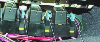
Console additional mounting block
You can find it inside the center console. It is located behind a plastic cover attached with screws, to the left of the front passenger seat. The block contains three relays and three fuses. In particular:
- Fan motor relay;
- Ignition relay;
- Fuel pump motor relay;
- Engine ECU and ignition module fuse;
- Fuse for electronic elements of the fuel supply system;
- Fuse for the electrical circuit of the speed and oxygen sensors, as well as the air flow meter and the canister purge valve.
The power of all fuses is rated at 15 Amps.
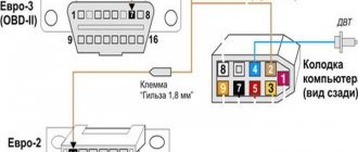
Numbering of plugs in the connecting blocks of the mounting block and the colors of the wires connected to them
In the diagram, the letters indicate the following colors:
- B - white;
- Ch - black;
- F - yellow;
- O - orange;
- G - blue;
- P - pink;
- Z - green;
- C - gray;
- K - brown;
- P - red.
If the letters are together, then wires of two colors must be connected to the plug.
Changes in switching and layout of mounting blocks
The most important innovation in the VAZ 2110 fuse box from old to new models affected the location of the fog lamp fuse. In the first modifications, this device was located behind the block, and not inside it, and was supported by a bundle of wires, without being equipped with a board. Over time, the designers provided a special board for it, which was still located outside the main unit, but was placed to the left of the console. Only ten years later did it find a place among the other fuses.
Blocks with different layouts differ in numbering. The first models with 6 relays have the number 2110-3722010, while those equipped with 7 devices were marked 2110-3722010-08, and the most modern ones - 2110-3722010-01. Modifications that do not have relay legs for turning on the front lighting are marked as 21110-3722010-12. Also, the manufacturer produces units equipped with legs, but not relay K1, which can be either with or without jumpers - in both cases, independent installation of the device or jumpers instead of it is allowed.
Advantages of injection models
The main function of the pump is to supply fuel to the combustion chamber. It must meet certain requirements. The main criterion is pressure.
The pumps for injection and carburetor engines are different. Thanks to the engine with direct fuel injection, there is no need for preliminary preparation of the combustible mixture. As you know, the carburetor is the weak link. Difficult adjustments, clogged jets, difficult starting in cold weather create inconvenience for owners of classic VAZ brands.
Tens and VAZ-2112 internal combustion engines have significant advantages. Let us note the advantages of injection units:
- support for environmental standards;
- direct injection into the combustion chamber;
- fuel economy;
- system reliability;
- increased engine power;
- starting a cold unit without warming up;
- dispensing a portion of the mixture;
- The fuel module is controlled electronically.
Unfortunately, the injector has a number of disadvantages. Maintenance and repairs have to be carried out at a service station. It also requires qualified personnel and a computer to determine the malfunction of electronic components. Let us point out other disadvantages:
- design complexity;
- high requirements for the octane number of gasoline;
- complex diagnostics and repairs;
- expensive spare parts and equipment.
Types of mounting blocks
VAZ 2110 has 2 types of mounting blocks:
- basic;
- additional.
The first contains most of the fuses and relays in the vehicle's power supply circuit. The second one houses the devices responsible for the motor power supply circuits. Over time, the main block experienced a number of transformations and modernizations - there were three in total. The main difference between them is the number of relays. From the first models to today, it has grown from six to eight.
New mounting block
The area required updating with each modification of the VAZ 2110. It was necessary to correct some design flaws that were noticeable from the very beginning. The fog lamp fuse did not have a circuit board and was hanging on a bundle of cables next to the mounting block itself.
The first change in the layout of the main mounting block occurred precisely in connection with the placement of a fog lamp fuse in it, as well as an increase in the number of relays. In the updated modification of the latter there are not 6 or 7, but 8.
Particular variability in new block modifications is associated with the presence or absence of the K1 front light relay: some models have only legs and jumpers that require cutting when installing K1 yourself, or just the legs, without jumpers. In other modern units they also install the relay itself.
Old style mounting block
There are six relays and 20 fuses. Its location is the same as that of modern models. Over time, another relay was added, responsible for the front light. Otherwise, its design is no fundamentally different from subsequent ones.
Description for Renault Kanga 2nd generation
Communication block
It is quite difficult to get to it. To do this, you need to remove the battery, unscrew the cover of the unit next to it and turn it over.
Scheme
Description
| 1 | 7.5A - Fuse for right side light bulbs (172-226) |
| 2 | 7.5A - Fuse for left side lights (173-227) - right rear light (172) - middle license plate lamp (1324) cigarette lighter (101) - socket for additional equipment of the 1st row of seats (506) - door lock and emergency switch alarm (1391) - headlight range control switch (562) - climate control panel (319-419) - audio system (261) - multifunction display |
| 3 | 10A - Right headlight fuse (low beam) (226) - headlight range control switch (562) - right headlight range control motor (538) |
| 4 | 10A - Left headlight fuse (low beam) (227) - left headlight leveling motor (537) |
| 5 | 20A - Fuse for right and left fog lights (176-177) |
| 6 | 10A - Left headlight fuse (high beam) (227) |
| 7 | 10A - Right headlight fuse (high beam) (226) |
| 8 | 25A - ECU of the anti-lock brake system (118) or trajectory stabilization system (1094) |
| 9 | 30A - Windshield wiper motor fuse (212) |
| 10 | 5A - Fuse “+” after the ignition switch of the electric power steering (1232) |
| 11 | Not used |
| 12 | 20A - automatic transmission ECU (119) |
| 13 | Not used |
| 14 | 15A Car with a gasoline engine: injectors 1-2-3-4 (193-194-195-196) – adsorber (371) – lower oxygen sensor (242) – upper oxygen sensor (887) or Car with a diesel engine: supply regulator fuel (1105) – cylinder sensor solenoid valve (746) |
| 15 | Not used |
| 16 | 5A - automatic transmission ECU (119) |
| 17 | 7.5A - Auxiliary heater relay 1 (1067) - Auxiliary heater relay 2 (1068) - Diagnostic connector (225) - Airbag/seat belt pretensioner ECU (756) - Parking assist ECU (1222) |
| 18 | 5A - Fuse "+" after the ignition switch, water in fuel sensor (414) - relay unit in the engine compartment 2 (1683) - injection computer (120) |
| 19 | 10A - Fuse “+” after the ignition switch of the reverse light switch (155) or the reverse light switch with top dead center sensor (1109) |
| 20 | 20A -Injection computer (120) |
| 21 | Not used |
| 22 | 10A - Fuse for the electromagnetic clutch of the air conditioning compressor (171) |
| 23 | 30A - Heated rear window (200) - outside rear view mirrors (239-240) |
Power supply circuit block
Scheme
Purpose
| 1 | 60A Coolant Heater Interface Unit |
| 2 | 7A Diesel engine glow plug relay unit (980) - coolant heater interface unit |
| 3 | 30A Relay block in the engine compartment 2 (1683) – heating element of the fuel heater |
| 4 | 40A Door Power Window Motor Fuse |
| 5 | 70A Fuse and relay box in the passenger compartment |
| 6 | 50A ABS ECU (1094) |
| 7 | 40A Additional heating relay 1 |
| 8 | 70A Fuse and relay box in the passenger compartment |
| 9 | 70A Additional heating relay 2 |
The design and principle of operation of the relay
First you need to understand how this device works and what functions it performs. A relay is an electromagnetic switch that connects and disconnects a circuit when certain conditions are created. In appearance, it is a box with a plug with American-style outlets.
The relay has 9 terminals, each of which is marked with a special marking:
- Voltage + 12 V has three pins - regardless of the ignition, this voltage has pin 30, when the starter is running - marked 50, when the ignition is running - marked 15.
- Signals from the ignition system are transmitted by TD.
- Information about the engine temperature from the unit that controls the injection KE is transmitted by TF.
- Mass - pin 31.
- There are also three outputs: 87V is responsible for turning on the starting injector, 87H is used to heat the oxygen sensor, and 87 supplies power to the fuel pump or fuel pump.
Fuel pump relay diagram
All of the above functions must be performed by the relay; if it fails to cope with at least one, then a breakdown has occurred. To understand what led to the failure, you need to understand on what principle this mechanism works.
When the driver turns the ignition to the “ON” position, the relay is activated and the pump begins to build up pressure in the pipes through which the fuel flows. In some cars, the TN is activated when the driver's door is opened. The relay turns on the fuel pump for a few seconds, inside of which there is an electric motor that raises the pressure to operating pressure. In the future, the pump will only start under certain conditions. To do this, the engine must be running, or this is possible when the engine is cranked with the starter.
Fuel pump relay
When the VT turns on, a characteristic click is heard, and if it is not there, the car will not start. During the test, it is important to consider that even a broken relay can function when the starter is turned on and the control transistor is working.
When starting a “cold” engine, the starting injector and starter operate for the same period of time. The length of the time interval depends on the temperature of the engine. The injector operating time is set by a relay based on temperature readings received from the injection control unit. On older cars there was no heating of the oxygen sensor, but on new ones it is started in various ways. In some relay models, the sensor is turned on simultaneously with the pump.
How does the device work?
After the driver turns the key in the ignition switch, the relay begins its work. The part sends a signal to the fuel pump and it turns on for 2 - 3 seconds to achieve the required pressure in the rail. The relay turns off the pump and then it starts only when the engine is rotated by the starter or while driving. After stopping the engine, the relay turns off the fuel pump and relieves pressure. In the latest models of gasoline pumps, the device performs several additional functions:
- Acceleration. If the automatic transmission needs to increase speed, the relay can additionally turn on the pump to supply more fuel.
- Slowing down the engine speed. If the engine is running at maximum speed, the relay may temporarily turn off the fuel pump. Temporarily turning off the device allows you to normalize the number of engine revolutions.
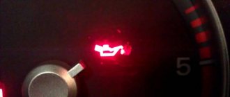
A sign that the fuel pump is working is a slight hum. Normally, the hum lasts only a few seconds, but if the relay or other parts of the system fail, the device may not turn off for a long time or may not turn on at all.
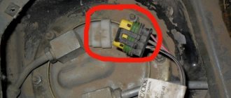
Where is it located?
Often, to fix a breakdown in the fuel system, you need to change the relay. It is located in the car interior near the console. To access it, you need to remove the protection cover.
Unscrew the two fastening screws.
Remove the cover.
Fuel pump relay number 5 in the diagram:
Fuse diagram in the power unit.
Where is
The relay can be easily found on the circuit board of the mounting block along with other control modules. Each manufacturer implemented the block placement scheme in its own way. Thus, on VAZs, the mounting blocks were located in the car interior under the glove compartment or were hidden in the right side of the interior heater console.
In the vast majority of modern car models, the mounting block is located in the engine compartment of the car. It is relatively easy to recognize by the FUEL PUMP type designation and is externally a standard rectangular case with pin legs, usually black, blue or brown. The relay itself is inserted with legs into the socket of the switching panel and, as a rule, is adjacent to several relays similar in appearance and size, which are responsible for turning on and operating the starter, electric radiator fan, air conditioner, and various heaters. The device itself can be pulled out of the socket with a little effort, but only with the battery disconnected.
The contacts on the relay body are numbered in accordance with the DIN 72552 standard. Therefore, their purpose in the wiring diagrams of any car will be the same.
The simplest relay options have four contacts. Two of them are intended for connecting power wiring from the pump motor, another two are for receiving a control signal from the ECU. An example of the simplest four-pin relay is the version installed on the Hyundai Accent or Kia RIO.
Fuel pump relay - main contacts on the relay housing:
- 30 – power wiring contact;
- 87, 87a or 88 – power wiring contacts. On the wiring diagrams of foreign models, this contact is marked with the number 87a, in Russian products - 88, but there is no fundamental difference in the operation of the relay;
- 86, 85 – contacts of the electromagnet coil winding, receiving a control signal from the ECU.
Contact No. 30 is mandatory, it is present in all models of fuel pump relays, in the idle position it is closed to terminal 87a, and when the engine starts, it is connected to terminal 87. After resetting the power from the starter, the fuel pump control relay will keep its operating contacts closed until the engine stops.
In a four-contact relay, two contacts, 87a or 87, are combined into one, and the device will operate as an electromagnetic power circuit switch.
https://youtube.com/watch?v=CV1xNbemKUA
Signs and Symptoms of a Bad Fuel Pump Relay
Let's start with the fact that the fuel pump is controlled through a relay according to the following general scheme:
- the driver inserts the key into the lock and turns on the ignition;
- after turning on the ignition, the relay turns on the fuel pump for 2-3 seconds, which is necessary to create pressure in the fuel rail.
- then you can hear a characteristic sound as the fuel pump relay clicks, which has turned off the fuel pump;
- subsequent operation of the fuel pump will be possible under 2 conditions: rotation of the engine by the starter during startup and further independent operation of the already running engine.
- after turning off the ignition and stopping the engine, the relay turns off the fuel pump immediately or after 1 second.
Also on some cars the device serves as a kind of engine speed limiter. If the engine speed approaches maximum and begins to exceed the permissible threshold, the fuel pump is switched off via a relay. The gasoline supply stops, the speed decreases, after which the element supplies power to the pump again.
It should be additionally noted that on some vehicle models the fuel pump does not turn on after turning the key in the ignition, but at the moment the driver's door is opened. This solution allows you to quickly start the engine, as it ensures that the necessary operating pressure is created in the fuel system in advance. In other words, the pump pumps gasoline until the driver decides to insert the key and start the engine.
If the relay malfunctions, then power may not be supplied to the fuel pump. The second option is that the pump hums or hums constantly, that is, it does not turn off a few seconds after the required pressure is created in the fuel line. In the first case, the engine often cannot be started because the pump does not pump and there is no gasoline in the fuel rail. In the second case, the fuel pump relay gets stuck (the fuel pump relay does not work) and the battery charge is consumed for the constant rotation of the fuel pump motor. Let us add that on some cars, starting the engine is possible even if there are certain malfunctions in the operation of the element, since the pump relay connection diagram allows the device to operate while the starter is cranking.
Causes of fuel pump relay malfunction
Most often, anomalies in operation are associated with natural wear of the part. There are times when there is little fuel left in the tank and the engine stops starting. The gasoline sensor sends a signal to the ECU that there is a lack of fuel, and the system blocks the fuel pump. When the part is new, you need to look for another reason:
- Ingress of water - in this case, there are oxides on the surface of the part, and corrosion may occur. This breakdown is often observed during the cold season.
- Broken capacitors.
- To find out why the system failed, you need to consider the type of engine. In the case of a carburetor.
- Short circuit or electrical fault. This is often due to the use of fuses that are of the wrong value.
- Got a defective relay.
- Incorrect installation of the immobilizer - in anti-theft systems, the operating principle is usually based on blocking the power supply to the voltage transformer. In such a situation, the problem lies in the immobilizer, and it is this that needs to be checked.
If oxides have appeared, after cleaning the contacts the relay will still work. To avoid subsequent damage due to moisture, you can treat them with WD-40 lubricant. A working relay may overheat and not operate, or it may start up late. This anomaly is explained by a broken fuse.
You should not troubleshoot the breakdown yourself; only if water gets in, the relay can be cleaned and continued to be used. Purchasing a spare part will not require any special expenses; you can install it yourself. For example, a TN relay for a domestic car will cost around 100 rubles. Relay malfunctions and their causes can be found in the table:
| Main malfunctions associated with relays and their causes | ||
| Sign | Type of malfunction | Possible reasons |
| When the ignition is turned on, there is no sound of the fuel pump running. | No power is supplied to the fuel pump. | Short circuit. A defective relay has been installed. Natural wear of the part. |
| Contacts are oxidized, rusted or damaged. | It starts poorly and the engine stalls while driving. There may be extraneous noise. | Water ingress, condensation, short circuit. |
| The car stopped starting after installing a non-standard immobilizer. | Blocking the power supply to the fuel pump. | Incorrect installation of the immobilizer, or incompatibility with the new security system. |
| The pressure in the fuel system is less than optimal for this car model. | The fuel pump pumps poorly and does not create the required pressure. | Wiring problems, relay or fuse fault. |
Master node of the system
The VAZ-2110 fuel pump is equipped with an electric drive. Its body is lowered into the fuel tank. Gasoline is both a pumpable fuel and a coolant. It should be remembered that traveling with an empty tank is fraught with overheating of the VAZ-2110 injector fuel pump.
This electrical device is an independent unit. Accordingly, its operation does not depend on the state of other mechanisms. A necessary condition for rotating the VAZ-2110 fuel pump rotor is maintaining normal voltage on the on-board network.
The voltage comes through the ignition switch. When the key is moved to position 1, the circuit is closed to turn on the drive. The VAZ fuel pump fills the fuel rail. The engine is ready to start.
If symptoms of poor fuel system performance occur, the pump should be checked. We list the signs that make it possible to replace the VAZ-2110 fuel pump:
- the car is malfunctioning;
- accelerates poorly;
- twitches while driving;
- won't start at all
- gasoline does not flow to the ramp.
First of all, a hearing test is performed. After turning the ignition key to position No. 1, there should be a noise under the rear seat. The sound lasts for a couple of seconds. This means that the pump has pumped up the required pressure.
How to understand that you need to check the fuel pump relay
You can determine that the relay is faulty by paying attention to the following anomalies during the operation of the VT:
- The pump stopped turning off when it reached the required pressure, which is manifested by an unpleasant hum.
- There is no characteristic sound when the ignition is turned on.
- No power is supplied to this unit.
- The engine does not turn on because it is not connected to the power supply of the VT.
- In some car models, even when the maximum permissible engine speed is exceeded, the fuel pump turns on. But it may not start the first time, the engine stalls while driving, or there is noise coming from the running pump.
What tools will you need?
To check, take a test lamp, the current consumption of which should not exceed 0.25 A. Instead, you can use a multimeter - a device that has the functions of a voltmeter, ammeter and an apparatus for measuring ohmic resistance. To unscrew the relay blocks, you will need wrenches corresponding to the diameter of the bolts.
It is advisable to have a relay diagram, main characteristics and current values with you. As a rule, the necessary data is applied to the device body. Typically, on most models, the connectors are located according to a standard layout. But it’s better to know the exact location so you can check the number of contacts later. The standard relay layout is shown below:
Checking the fuel pump relay yourself
At the beginning of the test, you need to get to the following elements: the pump fuse and its relay. Having decided which relay is responsible for the fuel pump, you should also inspect the fuse. Additionally, you need to check the fuse because the fuel pump relay heats up and then does not respond in a timely manner or does not operate at all due to a malfunction of the specified fuse.
The easiest way to check is to install a known working device. Also in the list of general ways to check a fuel pump relay with your own hands, you can highlight one when a test lamp is connected instead of a relay. After turning on the ignition, the light should light up. You can also place a jumper on the terminals during diagnostics. If after turning the ignition key the fuel pump starts to work, then this indicates a malfunction in the fuel pump control device.
Now let's look at another available way to check using the example of a VAZ 2110 car. The fuel pump relay itself in this model is located near the fuse.
- To check, you will need a multimeter or a test light of no more than 0.25 A. Next, you should alternately measure the voltage at the control terminals of the device, simultaneously fixing the contact to ground. This method allows you to accurately determine whether the fuel pump relay needs to be replaced.
- If the warning light does not light up, the pump fuse is working or replaced with a known working one, then attention should be paid to the wiring from the relay to the computer. At the same time, the possibility of malfunctions in the engine control unit should not be ruled out.
Finally, we add that the element may also refuse to work or stick after failures or unqualified installation of a car alarm/immobilizer. The fact is that security and anti-theft systems with an engine start blocking function are often based on interrupting the power supply to the fuel pump. In this case, these systems must be diagnosed separately.
What will happen to your car if you don't check the fuel pump relay?
The likelihood of an emergency situation increases, because the engine may stall while driving on the highway. It is impossible to predict how a broken relay will behave and at what point it will stop performing its functions. It happens that in the morning the car starts for the nth time, but in the evening the pump does not react at all to turning the key. As a result, you may need to call a tow truck, for which you will have to pay a lot of money.
Diagnostics
A malfunction of the VAZ 2114/2115 fuel pump can be caused by:
- malfunctions in the device’s power supply circuit;
- failure of starting and protection elements (relay and fuse);
- wear of electric motor parts.
Checking the electrical circuit
At the beginning of the diagnosis, you should check the electrical circuit of the fuel pump. To do this you will need:
- car tester (multimeter);
- crosshead screwdriver;
- two pieces of wire about 2 m long.
Checking the electrical circuit is carried out in the following order:
- Turn on the ignition without starting the engine. When the key is in the first position, a click should be heard, characteristic of turning on the relay, followed by a slight whirring of the pump electric motor. If there is no click, the relay is faulty or is not receiving power. If there is a click, but no buzzing, the wiring coming from the relay or the pump motor itself is faulty.
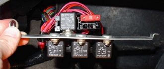
- Under the glove compartment, find an additional mounting block consisting of three relays and three fuses. The pump relay is located in the middle, and the fuse is located to the left of it. Remove the fuse from its socket, test it with a multimeter, and if the result is negative, replace it. When replacing the fuse, please note that it is rated for a maximum of 15 A.
The relay and fuse for the fuel pump on the VAZ 2114/2115 are located in the mounting block under the glove compartment.
Set your multimeter to voltmeter mode. Connect one probe of the device to the relay terminal to which the pink wire fits, and the second to the car body. Turn on the ignition. The device should show the on-board network voltage in the range of 11.7–12.4 V. If there is no voltage, the problem may be a broken wiring or a malfunction of the ignition contact group. In this case, it is better to contact an auto electrician. If power is supplied, check that the relay is working. With the ignition on, use a screwdriver or a piece of wire to close the contacts to which the pink and gray wires go. This closes the circuit bypassing the relay. If the fuel pump works, replace the relay.
The ground wires of the fuel pump are attached to the body with a self-tapping screw
Pressure check
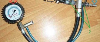
If the pump is working properly, but the engine begins to operate intermittently, you should check the fuel pressure in the system. For this you will need:
- pressure gauge (can be a tire gauge with a measurement limit of 5–7 kPa);
- petrol-resistant hose with a diameter of 10–12 mm and a length of 50–80 cm;
- two clamps for a hose of the appropriate diameter;
- Phillips screwdriver;
- nipple cap;
- dry rag.
In addition, the presence of an assistant is desirable.
The verification procedure is as follows:
- In the engine compartment on the engine fuel rail, locate the pressure measuring fitting (on the right side).
- Remove the plastic cap (plug) from the fitting.
Find the pressure fitting and remove the cap from it
When unscrewing the spool valve, fuel may spray out of the fitting.
Connect the pressure gauge to the fitting using a hose and clamps
Features of relay operation with car alarms
In cars that have an alarm system with an ignition blocking function, there are sometimes situations where the alarm is the cause of the relay malfunction. Most anti-theft systems block the operation of the fuel pump, so that fuel does not enter the system and the car does not drive. If the system was not installed correctly, it is possible that the alarm is preventing the relay from operating. Part repairs are not always necessary in this case. Sometimes it is enough to disconnect the output to the pump or reconnect it.
It is necessary to trust the installation of car alarms only to professionals, since a violation of the technology can lead to a decrease in the functionality of the equipment and damage to various vehicle systems.
Video instructions for replacement
In this short article you will learn about the VAZ 2110 fuel pump relay. Such a device can be found not only on tens, but also on nines (injection), as well as more modern Priors and Grants. But why is this relay needed and what to do if it fails? This is what we will now try to figure out. But it’s worth starting with the principle of operation of the fuel supply system of the VAZ 2110 car.
Mechanical fuel pump "tens" VAZ
The VAZ 2110 (Lada-110) car has been produced at AvtoVAZ since 1995, and the first engines on this model came with carburetors. Eight-valve VAZ 2110 engines with a power of 72 hp. With. were set to “tens” until 2000, and the fuel pumps on these internal combustion engines, accordingly, were mechanical.
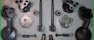
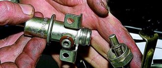
The 2110 mechanical fuel pump consists of parts:
- metal case (two halves);
- top cover;
- pusher with diaphragm;
- two valves;
- return spring.
Gasoline is pumped from the fuel tank by oscillating the diaphragm and opening and closing valves. The diaphragm with a pusher is driven by the camshaft eccentric; on the lower BN housing there is a manual pumping lever for gasoline.
Checking relay power.
In the case when the fuel pump relay turns on when the ignition is turned on, but the pump itself does not work, you need to check the power at terminal 87 of the fuel pump relay. To do this, touch terminal 87 of the relay socket with the output of the control lamp connected to the vehicle ground, and the lamp should light up. If the lamp does not light, it means the fuse has blown or there is a break in the wire.
If there is power at terminal 87, you should remove the relay from the socket, and instead place a jumper between pins 87 and 30. In this case, if the pump and connecting wires are working properly, the pump should start working and if this happens, the relay should be changed. If the pump does not start working, then, without removing the jumper, you need to touch the power wire on the fuel pump with a test lamp connected to the vehicle ground.
Checking the fuel pump power circuit.
If a submersible pump is installed on the car as part of the fuel module, you need to remove the connecting connector and touch one of the thick wires. When you touch one of them, the indicator lamp should light up. If the lamp does not light up on any of the wires, then it is necessary to eliminate the break in the wire from the fuel pump relay to the module connector or the pump itself, if the pump is of a remote type. One of the reasons for the break may be the anti-theft blocking of an installed non-standard alarm system.
In the case when the test lamp lights up on one of the thick wires of the connector or one of the terminals of the remote pump, you need to connect these terminals with a test lamp to each other. In this case, the control lamp should light up. If the lamp does not light, it is necessary to eliminate a break or poor contact in the wire connecting the pump to the vehicle ground.
If, when checking the wires and relay for turning on the fuel pump, no malfunction is detected, the electric motor of the fuel pump or its connection to the module connector is faulty. It is not difficult to find the cause by removing the fuel pump module from the tank. If there is poor contact with the connector, melting of the plugs will be visible. If melting is not noticed, then to check the pump itself, you can connect it to the battery. It should be taken into account that operating a submersible pump without liquid will damage the pump. A faulty pump should be replaced.
Purpose
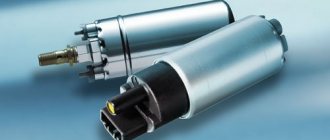
Electric fuel pump VAZ 2110
The principle operation of an electric fuel pump is based on pushing fuel under pressure into the engine. Conventional VAZ fuel pumps suck gasoline from the gas tank; a small gap from the pump to the carburetor allows it to operate at low pressure. Electric fuel pumps of the first VAZ cars worked at the same speed. The industry has launched the production of pumps that meet the growing requirements of the automotive industry; now their operation is completely dependent on the speed of the engine.
Note. The vehicle's electronic system controls the operation of the fuel pump. It corresponds to several factors: ambient temperature, what position the throttle is in, and the composition of the exhaust gases.
Electric fuel pumps operate under pressure, resulting in increased noise and rapid heating. For these reasons, they are installed in the gas tank. Gasoline cools and muffles the sound of the running pump.
How to disassemble the starter solenoid relay on a VAZ 2110
When operating a VAZ 2110 car, it may happen that at one point it stops starting. When the engine starts, the driver will not hear characteristic sounds, but instead, the operation begins to be accompanied by a strange hum. This may reliably indicate problems with the starter relay. In such a situation, the VAZ 2110 requires replacement of the solenoid relay.
Sometimes it happens that the device operates normally and nothing indicates a breakdown. But suddenly, in order to start the car, you have to push it. The only radical solution to fix the problem is to replace this part. In this regard, another question arises: how to change the solenoid relay on a VAZ 2110? You must understand that replacing it requires dismantling. This review will tell you how to do this in practice.
Purpose of the retractor relay
It exists to remotely turn on the electric starter motor. This is necessary so that the bendix and flywheel mesh. This design consists of various systems with a return, contact and magnetic mechanism. They serve to turn on two coils. The core is represented by a pipe in which the anchor is located. There is a winding of copper wire there. At one end it is connected to the electric motor, and at the other to the housing.
Due to the created electromagnetic field, the armature moves in the core. When the voltage disappears, the armature takes its original position. When power is applied, a magnetic field is generated. When it operates, the return springs are retracted. Starting the engine causes the voltage to disappear. The spring pressure on the armature causes it to return to its original position. In this case, the contacts open.
When replacing the starter solenoid relay, you need to make sure that it is the problem.
To check the operation of the starter, you need to take a battery and two wires:
- First you need to remove the starter.
- The relay output is connected to the positive terminal of the battery.
- The connection point for the second cable is the starter ground.
If there is a click, you can tell that the Bendix is working. It is accompanied by a fast and sharp sound. A sluggish, prolonged click indicates some kind of malfunction. Then the device needs to be replaced, and it is purchased at a car dealership.
Algorithm of actions for replacement
When it is necessary to replace the device, the question immediately arises of how to disassemble the VAZ 2110 starter solenoid relay. If there is a non-removable starter, the relay needs to be replaced completely.
In the case of a collapsible starter, the following actions are carried out:
- it is necessary to unscrew the screws located on the relay housing cover. Sometimes the ends of the winding need to be unsoldered;
- It is necessary to check the power contacts. Quite often this is the cause of the malfunction. If the contacts are completely burnt, they need to be replaced. If the defect is minor, then the surface is cleaned with sandpaper;
- The order of assembly upon completion of the actions is in reverse order.
When purchasing a new device, you should take the old element with you. This will help you avoid mistakes when purchasing. The device is secured with three screws.
Sources
- https://rus-avtomir.ru/remont/rele-vaz-2110
- https://avtoskill.ru/remont-obsluzhivaniye/kak-proverit-rele-benzonasosa.html
- https://motorsguide.ru/system/rele-toplivnogo-nasosa
- https://carfrance.ru/kakoj-predoxranitel-otvechaet-za-benzonasos-na-vaz-2110/
- https://KrutiMotor.ru/zamena-rele-benzonasosa/
- https://scart-avto.ru/remont/gde-nahoditsya-rele-toplivnogo-nasosa-3-vozmozhnyh-mesta/
- https://vaz-2110.ru/elektrika-i-provodka/rele-startera-na-vaz-2110.html
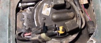
Removing the pumping unit
Before starting work, you must disconnect the terminal from the battery. This will prevent damage to electrical equipment. In addition, replacing the fuel pump may cause a fire.
Let's prepare tools and materials. To remove the VAZ-2110 fuel pump, you need the following:
- Screwdriver.
- 10mm socket wrench.
- Collar.
- Open-end wrench 13.
- Rags.
The device itself is located under the rear seat cushion. To get to the installation location of the fuel pump 2110, you need to remove the seat. Under the casing we find a hatch. We unscrew the hatch. Disconnect the electrical drive connector.
Using an open-end wrench, unscrew the tips of the fuel pipes. We pull off the pipes. Using a spanner, unscrew the 8 nuts around the perimeter of the clamping ring. Release the flange.
There is a gasket under the pressure ring of the fuel pump 2110. The gasket is removed. It is better to change worn tires.
Then we raise the VAZ fuel pump together with the float. Gasoline will leak from the body. To avoid staining the interior, place a rag. There will be up to 1 liter of gasoline left in the old building. Drain it into the tank.
Assembly is carried out in reverse order. There is an arrow on the top of the cover. It should point towards the trunk. This is the correct pump position.
When replacing, do not forget to remove the float and level sensor.
These spare parts are installed on the new structure.
All operations, including preparation, will take less than an hour. After replacement, perform a test. Start the engine. Finally, you should check the fuel pump, make sure the connections are tight and there are no leaks.
Schematic electrical diagrams, connecting devices and pinouts of connectors
The fuel pump on a car is designed to supply fuel to the combustion chamber. Its operation is controlled using a relay. On a VAZ (depending on the model), the fuel supply unit can be electrical or mechanical - it all depends on the fuel supply system. On a fuel-injected car, the fuel pump is located in the tank. When the ignition is turned on, voltage is supplied to the terminals of the unit and it begins to pump fuel. If the required pressure is created in the system, the relay automatically turns off the fuel pump - the engine is ready to start.
Basic principles
Regardless of the type of engine used, the basis of the wiring used in the VAZ 2110 car is the same. It's easy to find a diagram, but not so easy to understand.
Let's look at the basic principles of wiring.
- All equipment and devices powered by electricity in the VAZ 2110 are based on a single-wire connection. VAZ designers specially provided for wires of certain colors to each be responsible for their own functions. Therefore, certain equipment is connected using wires of their own color. This allows you to independently understand the wiring, make it easier to carry out repair work and not spend money on car repair services.
- The downside to the VAZ 2110 is that the mass is the car body itself.
- The positive wire of the batteries on the top ten always comes only in red. Therefore, when making repairs, try not to change the color of the wire, so as not to confuse yourself.
- For each system that is connected to the electrical system, it is equipped with its own separate wiring harness.
- The VAZ 2110 is designed in such a way that when the battery is turned on, all electrics and electrical equipment are energized. This is related to the most common recommendation, which you have seen more than once in our materials, where we described the repair or replacement of certain components - disconnecting the negative terminal from the battery.
- Do not forget about the existence of the so-called contactless system. This system is required to create a high-quality spark, which is simply necessary to ensure combustion of the air-fuel mixture. In order for a contactless system to function, high voltages are indispensable.
What do the measurement results say?
If the pressure is too low or rises very slowly, it is necessary to find out the reason. The culprit may be either a worn fuel pump, a dirty fuel filter or a pressure regulator. To remove suspicion from the latter, you need to clamp the fuel drain line with a clamp. If the pressure increases, then the regulator is faulty.
If the pressure in the system is too high, it is necessary to disconnect the drain pipe and direct it into any suitable container. A drop in pressure indicates that the return line is clogged; if it does not change, the regulator is faulty.
After starting the engine, the pressure in the fuel rail should decrease by 0.5 MPa due to the fact that vacuum is applied to the pressure regulator. When you press the gas pedal sharply, it should remain unchanged.
Then you need to briefly clamp the fuel drain line or adapter hose after the pressure gauge. In this case, the pressure should double - this is the maximum that a working fuel pump is capable of.
If the pressure does not increase when clamped, and the operating pressure is within normal limits, this indicates that fuel does not pass through the fuel drain line, and the pump is worn out to such an extent that it is not able to overpower the fuel pressure regulator valve, or there is a fuel leak in the supply hose inside the tank. Other possible causes - low supply voltage and leaks in the fuel line - were noted at the first stage of diagnosis.
Next, you need to pay attention to the behavior of the pressure gauge needle when the engine is idling. Normally it should tremble a little
If the needle fluctuates greatly, the fuel pump screen is most likely clogged. The problem can be solved by washing or replacing. Sometimes the pressure regulator is to blame (this happens quite rarely).
Continue checking the fuel pump as follows. The ignition is turned off. The engine stalls, but the pressure should remain unchanged (in this case, the diagnosis is completed). If it drops, this indicates a malfunction of the pump check valve, a breakdown of the fuel pressure regulator, or a leak in one or more injectors.
To determine the cause, the engine is started again and turned off again, while the fuel supply line is pinched. If the pressure does not decrease, the problem is in the regulator; if it decreases, the problem is in the injectors.
The last thing you can check is the performance of the fuel pump and compare it with the nameplate values. To do this, you need to disconnect the fuel line at any convenient place after the fuel filter, turn on the pump for 1 minute and direct a stream of fuel into a measuring vessel. If the amount of fuel is less than the specified amount, either the fuel pump or the filter is to blame. To clear things up, you need to disconnect the fuel filter and check the performance again.