Along with other options for improving the units and systems of the VAZ 2107, a non-contact (electronic) ignition system (BSI) is being considered instead of the standard one. This modernization makes it possible to provide stable increased voltage on the spark plugs, which, in turn, makes it easier to start the engine and increases spark energy.
Installing and adjusting a contactless ignition system is quite a difficult task, so if you do not have sufficient skills in working with automotive electronics, it is better to entrust this work to specialists. If you feel that you are able to install the BSZ kit on a VAZ 2107 yourself, then carefully study these instructions and get to work.
To work you will need the following set of tools and materials:
- Key to 8;
- Key for 10;
- Key to 13;
- Phillips screwdriver;
- Two self-tapping screws;
- Drill with a drill of the same diameter as the self-tapping screws;
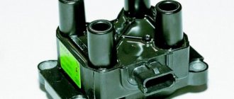
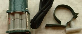
Naturally, in addition to all this, an electronic non-contact ignition system must be purchased, or rather a set of its components: a coil, a switch, a distributor and wires for connecting all the elements together.
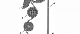
Below is a schematic diagram according to which the contactless ignition system for the VAZ 2107 is connected.
Setting the ignition timing with advance
This setup is completely easy to do. Even a beginner can cope with this task. To do this, prepare a 13 mm wrench and a special 38 mm crankshaft wrench in advance.
If your car is started, be sure to turn off the engine, since you can only turn on the ignition when the engine is turned off. First, the piston of the first cylinder is installed at the top dead center of the compression stroke, that is, in the ignition position. Before doing this, remove the candles and plug the hole from them with cotton.
You need to align the mark on the crankshaft and the front engine cover. To do this, use a wrench to start turning the crankshaft clockwise. During this action, the air compressed there should push out the cotton wool, thereby indicating the compression stroke. Continue turning the shaft slowly until the marks on the timing belt pulley and cover line up.
Please note that there are 3 marks on the cover:
- The first indicates ignition advance by 10º;
- the second – by 5 º;
- the third is equal to zero.
Since a VAZ 2107 engine with a carburetor runs on 92 or 95 gasoline, we need to set the ignition for these types of fuel. That is why you should select the second mark, which will indicate an ignition advance of 5º.
Once the required parameters match, put the spark plugs in place and remove the wires. The system is ready for use.
Installation Guide
How to install BSZ with your own hands on the “seven”? How to properly set and adjust the device? First you need to prepare everything you might need.
Tools and materials
To complete this task you will need:
- a set of keys;
- self-tapping screws;
- screwdriver set;
- construction drill.
Stages
Installation of electronic ignition must be carried out on a de-energized on-board network, otherwise a short circuit may occur in the system.
So disconnect the battery and then follow these steps:
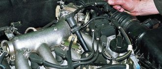
- Disconnect all high-voltage wires from the spark plugs.
- Dismantle the distributor cover.
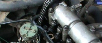
- After this, by rotating the crankshaft, it is necessary to set the slider to a position perpendicular to the axis of the power unit. Also mark the location on the middle mark of the distribution element scale, this will allow you to make adjustments without any problems in the future.
- The distributor fixing nut must be unscrewed, after which the device is dismantled.
- A non-contact regulator is installed instead of the dismantled distributor, while the slider and housing must be placed in the desired position in accordance with the previously established marks.
- The device cover is installed.
- Then you need to connect the high-voltage cables with the spark plugs.
- After completing these steps, you can replace the coil. In general, this task is quite simple, but when performing it, you should take into account the position of contacts B and K. If they are different on the new short circuit, then the element should be rotated relative to the fastener so that the contacts are located similar to the one that was installed previously.
- At the final stage of installation, the switch is installed; the best option would be to place it between the washer expansion tank and the headlight. The mechanism is fixed using self-tapping screws, and the so-called zero wiring should be brought out under one of them. As for the radiator, it should be leaned against the body.
Adjusting the ignition timing
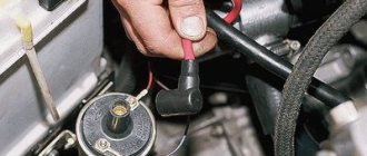
For subsequent actions, use a 13 key to loosen the fastening nut of the distributor (ignition distributor). Connect one wire from the light bulb (it will act as a voltmeter, that is, indicate the presence of voltage) to the low-voltage terminal that the coil has, the second to ground.
Now turn on the ignition. Slowly and carefully rotate the distributor body clockwise, stopping immediately when the light goes out. The sparks that appear will indicate the moment of ignition. Move the distributor counterclockwise until the contacts are disconnected and the lamp lights up again. Everything is in order, you can safely tighten the distributor, the setup is complete.
Contact distributor
All models and modifications of Zhiguli were equipped with contact type distributors until the early 90s of the last century. A distributor with serial number 30.3706 was installed on the VAZ 2107.
Design of contact breaker-ignition distributor 30.3706
The contact distributor consists of the following elements:
- frame;
- rotor (shaft);
- slider (rotating contact);
- contact breaker;
- capacitor;
- centrifugal and vacuum ignition timing regulators;
- cover with main (central) and four side contacts.
Housing and shaft
The base of the device is cast from aluminum. A cermet bushing is pressed into its upper part, playing the role of a support bearing for the distributor shaft. The side of the housing is equipped with an oiler through which the bushing is lubricated in order to reduce the friction force. The lower part of the shaft (shank) has splines for connecting additional engine elements to the drive gear. With their help it is set in motion.
Runner
A slider is installed at the top of the rotor. It is made of plastic and has two contacts connected through a resistor. Their task is to receive voltage from the coil through the central electrode and transfer it to the side contacts of the distributor cap. The resistor is used to eliminate radio interference.
chopper and capacitor
The breaker mechanism includes a group of contacts and a cam with four protrusions. The contacts are fixed on a movable plate, the rotation of which is ensured by a ball bearing. To be able to adjust the gap between the contacts, one of the mounting holes is made in the form of an oval. The moving contact is located on a spring-loaded lever. The other contact is stationary. In a calm position they are closed.
The cam is the thickened part of the shaft. Its protrusions serve to actuate the moving contact. When the breaker-distributor shaft begins to rotate, the cam with one of its protrusions rests against the movable contact block, moving it to the side. Then the protrusion passes the block and the contact returns to its place. This is the simple way to close and open the low voltage circuit in the contact ignition system.
Despite the fact that the voltage on the contacts is small, when they open, a spark is still formed. In order to eliminate this phenomenon, a capacitor is installed in the breaker circuit. It is attached with a screw to the distributor body.
Centrifugal regulator
The primary adjustment of the moment of spark formation in VAZ 2107 cars is carried out by turning the entire distributor . Further adjustments are made automatically. The function of the centrifugal regulator is to change the ignition timing depending on the number of engine crankshaft revolutions.
The basis of the mechanism design is the support and drive plates. The first is soldered to a bushing that is movably fixed on the distributor shaft. It can rotate relative to the shaft with an amplitude of 15°. On top it has two axles on which weights are installed. The drive plate is mounted on the upper end of the shaft. The plates are connected to each other by two springs of different stiffness.
When engine speed increases, centrifugal force also increases. It first overcomes the resistance of a softer spring, then a stiffer one. The weights rotate on their axes and rest against the support plate with their side protrusions, causing it to rotate together with the slider to the right, thus increasing the ignition timing.
Vacuum regulator
The vacuum regulator is attached to the distributor body. Its role is to adjust the ignition angle depending on the load on the power plant. The design of the device consists of a reservoir, a membrane with a rod located in it, as well as a hose through which the regulator is connected to the primary chamber of the carburetor.
When a vacuum appears in the carburetor, it is transmitted through a hose to the reservoir of our device. A vacuum is created there. When this happens, the membrane moves the rod, and it acts on the rotating breaker plate, turning it counterclockwise, increasing the ignition timing.
Contact type distributor malfunctions and their symptoms
Taking into account the fact that the distributor is a rather complex device, it is subject to the influence of a number of negative factors that can damage the elements of its design. That is why the distributor can have a lot of malfunctions. Well, as for common device breakdowns, they include:
- electrical breakdown of the lid;
- wear of the central electrode or side contacts of the cover;
- burning of the slider contacts;
- electrical breakdown of the capacitor;
- violation of the gap between the contacts of the breaker;
- wear of the moving plate bearing.
Installation of electronic ignition
Electronic ignition makes engine operation smoother and softer, makes it easier to start in the winter, and reduces fuel consumption. If you, having a carburetor engine, decide to switch to contactless (electronic) ignition, we will tell you how to correctly install it on a VAZ 2107 car.
An electronic system for a car with a carburetor should not be too expensive or cheap. It is best to opt for a product in the mid-price category, so that later you don’t have to change anything after a while.
Before work, prepare a drill and a set of keys.
For an overview, first read the included instructions carefully and open the carburetor type engine kit. It includes:
- ignition coil;
- distributor;
- switch;
- 4 candles;
- connecting and high-voltage wires.
The system is easy to install. First of all, remove the negative terminal from the battery and turn the crankshaft until marks numbered 3 and 4 align, that is, the highest dead center.
Now you can begin the main steps. The coil should be disconnected from all wires, remove it and install a new one. The coil can now be connected to the central high voltage wire. Connect 2 brown wires to contact “K”, and 2 blue wires to contact “B”.
Now remove the distributor cover. Please note that the slider must be set exactly as shown in the picture. Mark this place with a marker on the block to correctly install the new distributor. Now you can unscrew this part and put it to the side.
After opening the cover of the new distributor, place the slider perpendicular to the engine and insert it into the hole in the cylinder block. Align it with the mark on the block. Next, put on the cover and connect the wires.
Decide where the switch will be located, since there is no space for it in the VAZ 2107 car. We recommend installing it next to the washer reservoir. Secure it with self-tapping screws and install the connector.
Don't forget the candles. To replace them on a VAZ 2107 car, you will need a spark plug wrench, which you should use to unscrew the old spark plugs from the cylinders and put new ones in place.
Installation and connection of additional elements
Many cars do not have hood, trunk, or fuel filler door sensors. You can purchase limit switches, connect them in parallel and connect them to the control input. This is how, for example, they install the hood button:
One subtlety must be taken into account - the “open” position must correspond to a closed state. Installation is carried out in the following sequence:
- Secure the switch body;
- Additional wires are passed through the seal where the hydraulic corrector tubes pass;
- Connect the sensor, and at the same time the siren.
Now let’s add movement control to the car, that is, the alarm will “know” whether the car is actually moving.
Connecting to the speed sensor
Let's talk about the "Seven" with an injection engine. Then the speed sensor is installed and connected from the factory. It will be easy to find the contact of this sensor:
As you can see, you need to make a tap connected to one ECU terminal (1/59). Here we are talking about the control unit, that is, the standard engine controller.
Not every alarm system has a separate input connected to the speed sensor. But if the connection is still made, take care of good contact with ground. Under the “dashboard” there are two copper studs connected to the body. One of them is located near the ECU, and it is better to connect to it (see figure).
It would seem that the speed sensor is a fairly simple additional device. And if this element is missing, you can buy it and install it yourself:
The sensor housing must cover the hole in the gearbox housing. Everything looks simple, and you can do the installation yourself, but the tightness of the assembly will then be broken. In general, it's better not to take risks.
Subtleties of engine control
If autostart is not used, the alarm should not read data from the engine. Otherwise, it is necessary to implement control that allows you to turn off the starter at the right time. The control itself is usually carried out like this:
- The signal can read the value of the supply voltage;
- The cord from the generator is connected to the terminal of the VAZ-2107 tidy - the control cable can be connected to this terminal;
- It is best to control the launch using the tachometer, for which the alarm will still need to be configured.
The third option is preferable. The cord is not connected directly to the tachometer terminal, but through a capacitor and resistor:
Direct connection is used for “generator” control.
In practice, only one control method can be used. First, installation and connection are performed, then the system is configured.
Handbrake control
The dashboard diagram of the VAZ Seven looks like this:
The cord from the handbrake limit switch goes to terminal 8 (connector X2). Connect to this contact unless the instructions indicate that a diode must be installed. Otherwise, use terminal 4.
Connecting to the 4th terminal if the diode is not specified in the basic diagram is incorrect. Remember this and be careful.
https://youtube.com/watch?v=2ug2Eu6ajLM
Replacing the starter relay
Another common problem on VAZ 2107s with a carburetor is a malfunction of the starter relay. When you turn the key in the lock, the system makes a click, but the retractor relay does not operate. Replacing the relay is very simple.
First you need to remove the starter from the relay. Unscrew the 2 bolts that secure it. Slide it to the right and take it out, turning it backwards. Unscrew the nuts securing the starter and relay.
Turn it to the side.
Remove the 2 bolts securing the relay to the starter.
Install the new one in reverse order.
If you follow these simple steps, your VAZ 2107, which has a carburetor system, will serve you for many more years.
Vehicle dynamics, fuel consumption, exhaust toxicity and starting reliability on a carburetor “seven” depend on the correct setting of the ignition timing. The outdated “contact” system requires periodic maintenance and adjustment. Ignition adjustment on a VAZ 2107 with an injection engine equipped with a contactless ignition system is not required. But owners of outdated modifications of the VAZ 2107 have to go to a service station for adjustments or perform the operation themselves. This is not difficult to do.
Low pressure
For what reasons does the car pull to the left and how to fix it? Why won't the VAZ-2107 (injector) start? Problems may be hidden in low fuel line pressure. For normal starting of an injection engine, at least 2.8 atmospheres are required. You can check this by disconnecting the supply tube from the ramp. Use a pressure gauge for this. Malfunctions with the pump may occur due to frequent overheating. But how does this happen if it is submersible? The fuel pump is killed by driving on an empty tank. If the light comes on, do not delay refilling. The cost of a pump for an injection “seven” is 3 times higher than for a carburetor.
What is “ignition timing”
Ignition advance means the air-fuel mixture ignites before the piston reaches top dead center (TDC) during the compression stroke. This factor has a great influence on engine performance. A certain amount of time passes between the moment the spark occurs and the moment when the gas pressure in the cylinder reaches its apogee. Although this period of time is extremely short, due to the high speed of the crankshaft, during the time the mixture is ignited, the piston can travel a long way from the moment of sparking to the explosion of the mixture. When the advance angle is correctly set, the mixture explodes at the moment when the piston is at TDC and ready to move down. If the mixture ignites earlier (“pre-ignition”), it explodes during the lifting phase of the piston and interferes with the movement of the piston (the engine detonates). This leads to premature wear of parts and deterioration of engine performance. If ignition is done late (“late ignition”), the mixture explodes after the piston has left TDC, which leads to fuel burning out already in the exhaust manifold, a decrease in gas pressure in the cylinder and, therefore, loss of power and reduced efficiency. Therefore, installing the ignition on a VAZ 2107 is an important and necessary procedure. Sparking should occur at the most appropriate moment, which depends on the position of the gas pedal and crankshaft speed.
What is needed to install BSZ on the seven
The first BSZ kits, which were installed on injection engines, had an unreliable switch that often failed. At the same time, there was a need to replace it until the manufacturers improved the system. As a result, the weakest part of the contactless ignition module is only the Hall sensor.
To install the BSZ on the seven, you need to first prepare not only a set of necessary equipment, but also tools. These tools include:
- Screwdriver Set.
- Open-end wrenches for “8”, “10”, and “13”.
- Pliers or pliers.
- Spark plug wrench for replacing spark plugs.
- A drill for drilling holes in the body, with the help of which the switch will be secured.
- Key set to “36” to rotate the crankshaft.
When all the tools are ready for modification, we begin work. It is worth noting that installation is not difficult and can be done independently at home.
How to choose contactless ignition on a VAZ 2107?
As a result of the fact that VAZ 2107 cars were equipped with different engines, the BSZ system must be installed taking into account the design of the distributor. For power units with volumes of 1.3 and 1.5-1.6 liters, different distributors are purchased. In 1.3-liter internal combustion engines, a unit with a shortened shaft is installed, while in other engines the pulley has the same length.
The BSZ system includes:
- Distribution unit. Its catalog number is 38.3706-01 for a 1.3 liter engine. For power units designed for 1.5 and 1.6 liters - marking 38.37061.
- High voltage coil. Its catalog number is 27.3705.
- System control module. Catalog number 36.3734 or 3620.3734.
- Set of connecting cables.
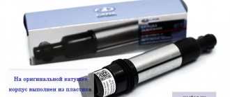
Switchgears for the VAZ 2107 and Niva VAZ 2121 models are similar in appearance, but they are different and are not interchangeable. “Nivovsky” mechanisms have different technical parameters and are not marked as such. If we talk about manufacturers, then products from SOATE have proven themselves on the positive side.
For proper operation of the BSZ, you will need new spark plugs - A-17DVR, they are not included in the package and must be purchased separately. For more efficient operation, it is recommended to install new high-voltage cables, especially if they have not been replaced for a long time.
The channel “ICE Theory” spoke in detail about the work of the BSZ and the features of choosing a system for classic models.
Necessary tool
To perform the work with the tool you will need the following:
- keys for 8, 10 and 13;
- crosshead screwdriver;
- two self-tapping screws;
- drill with a drill of the required diameter for self-tapping screws.
What causes an incorrectly set ignition on a VAZ 2107
An incorrect lead angle causes the following problems:
Engine overheating. Early ignition causes detonation, which changes the temperature regime of the engine. At the same time, the load on the crank mechanism increases, reducing their service life.
Reduced vehicle dynamics. Early and late ignition of the VAZ 2107 leads to the fact that fuel energy is not optimally consumed. The explosion of the mixture must occur exactly when the piston is at TDC.
Burnout of valves. With late ignition, the mixture continues to burn throughout the exhaust phase, causing the valves to overheat and “popping” to occur in the exhaust manifold.
Why turn on the ignition?
Incorrect ignition installation is a rather serious problem that haunts owners of cars with ZMZ-402 engines, but we are not talking about it now. The combustion of the flammable mixture must occur strictly at a certain time. If this timing is incorrect, the engine does not perform as it should.
Correct installation of the ignition on a VAZ 2107 can solve several problems, one way or another related to engine operation:
- Motor overheating. Often ignition too early causes detonation. Because of this, the engine temperature changes. The load on the parts of the crank mechanism increases, and its service life is significantly reduced.
Reduced vehicle dynamics. It does not matter before or after switching on, this malfunction will occur in any case. When an explosion occurs when the piston is at top dead center, all the energy from the explosion is transferred to the crankshaft and converted into torque. Therefore, the engine throttle is at its maximum at this moment.
If you set this earlier, the explosion will occur in the direction of the upward moving piston, which also exceeds the pressure in the cylinder. Of course, this slows down the rotation of the crankshaft, despite the considerable inertia of the flywheel.
- If the moment comes later than necessary, the piston will already fail during the explosion. When the piston reaches bottom dead center, the gases will continue to expand and some will escape into the exhaust manifold. Hence the pop in the exhaust manifold.
Ignition marks VAZ 2107
When adjusting the advance angle, you must focus on the marks marked on the crankshaft pulley and on the front engine cover.
There is a notch on the engine pulley that should align with one of three marks on the cover, depending on the fuel used.
The marks on the lid are of different lengths - short, medium and long. The first corresponds to an advance angle of 10 degrees, the second - 5 degrees, the third - 0 degrees (the mixture is ignited at TDC).
High octane fuel burns faster than low octane fuel. The VAZ 2107 is designed for gasoline with an octane number of 92-95, so the optimal advance for it is 5 degrees.
Armored wires
High voltage wires serve to transmit pulse voltage from the ignition coil to the fixed contacts of the distributor cover, and from there to the central electrodes of the spark plugs. The VAZ 2107 has five such wires. Structurally, each of them consists of a conductive core, several layers of insulation (PVC or silicone) and tips.
The set consists of five wires: four transmit voltage to the spark plugs, and the fifth serves to supply it from the ignition coil to the distributor
Wire faults
Armored wires can have only three faults:
- breakdown of the insulating layer;
- breakage of the current-carrying conductor;
- core wear.
Failure of one or more high-voltage wires at the same time is accompanied by the following symptoms:
- “triple” of the motor;
- its difficult to start;
- drop in power unit power;
- increase in the amount of fuel consumed.
How to check high voltage wires
Checking armored wires consists of determining the integrity of their insulation and establishing the resistance of the current-carrying conductors. To assess the condition of the insulating layer, it is enough to remove the wires, clean them of dirt and inspect them by twisting and bending them in your hands. If during such a check it is discovered that at least one of them has cracks, severe abrasions, or traces of electrical breakdown, the entire set should be replaced.
Long-term operation of high-voltage wires leads to wear of the current-carrying core, as a result of which its resistance changes up or down. Naturally, this affects the magnitude of the transmitted voltage and spark energy.
The process for measuring wire resistance is as follows:
- Turn on the ohmmeter and set it to the range 0–20 kOhm.
- We connect the probes of the device to the ends of the current-carrying wire.
- We look at the ohmmeter readings. Serviceable wires, depending on the manufacturer and service life, can have a resistance in the range of 3.5–10 kOhm. If the indicators are different, we change the wires as a set.
The core resistance should be in the range of 3.5–10 kOhm
Video: checking armored wires
How to set the ignition on a VAZ 2107
There is no need to adjust the ignition even in a garage. If you have the tools, you can set the lead angle literally on the street. The procedure is as follows:
- Allow the engine to cool (if it is hot). This will avoid burns during operation.
- Remove the high-voltage wires from the spark plugs.
- Unscrew the spark plugs (you can limit yourself to just the spark plug of the first cylinder, but with all the spark plugs unscrewed, there is no compression in the cylinders and it is much easier to rotate the crankshaft).
- Close the spark plug hole on the first cylinder with your finger (this will help determine the beginning of the compression stroke in the cylinder).
- Using a special key, rotate the crankshaft until the compression stroke begins (your finger should feel the air pressure).
- Continuing to rotate the crankshaft, align the mark on the pulley with the second mark on the front engine cover.
Repair of contactless distributor
To determine and eliminate the malfunction, careful diagnostics are required, which involves dismantling and disassembling the device. The only element of the distributor that can be checked without disassembling it is the capacitor. Let's start with him.
Capacitor check
As already mentioned, the capacitor serves as a kind of spark arrestor. It prevents the formation of an electric arc between the breaker contacts at the moment they open. To check its functionality, you must perform the following steps:
- Disconnect the low voltage wire connecting the coil and distributor.
- Disconnect the capacitor wire from the distributor.
- Connect these two wires to a regular twelve-volt car lamp.
- Turn on the ignition. If the lamp lights up, the capacitor is broken.
- Replace the capacitor, check how the engine works.
Removing the distributor from the engine
The distributor is installed in the engine cylinder block on the left side. It is fixed on a special bracket with one nut. To dismantle the device you must:
- Disconnect the “-” wire from the battery terminal.
- Unfasten the two latches securing the breaker-distributor cover to the housing.
- Disconnect all armor wires from the cover.
Disassembling the distributor and replacing faulty elements
The functionality of each part of the device can be determined already at the stage of disassembling it. To do this you need:
- Carefully inspect the distributor cover from the outside and inside. Particular attention should be paid to the central electrode (carbon) and side contacts. If wear, damage, or severe burning is detected, the cover must be replaced.
Video: disassembling and repairing a contact distributor
Installation of the distributor and setting the ignition timing
The distributor is assembled after replacing the faulty parts in the reverse order. There is no need to install the cover to the device at this stage. To install the distributor and set the correct ignition timing, you should:
- Engage neutral gear.
- Install the distributor into its seat, not forgetting the O-ring.
Video: setting ignition timing
Setting the angle of the closed state of the contacts
The stability of the engine operation depends on how correctly the angle of the closed state of the contacts (the gap between the contacts) is inserted. To configure it you need:
- Using a “38” wrench placed on the crankshaft pulley mounting nut, rotate the shaft until the moving contact lever stops on one of the cam protrusions.
After carrying out this work, you can install the cover on the distributor body, connect the high-voltage wires and try to start the engine.
Checking the ignition timing
First of all, you need to start the engine. If it started before, but after adjustment it doesn’t, it’s worth checking again that the advance angle is set correctly. If the engine is running, it is necessary to check the advance angle while driving:
- Accelerate the car to 45 km/h.
- Turn on 4th speed.
- Squeeze the gas pedal sharply.
- Detonation should occur for 2-3 seconds, and then, after accelerating the car, it should disappear.
If the detonation does not disappear after accelerating, the ignition is “early”. If detonation does not occur at all, ignition is “later”. To reduce the advance, you should unscrew the distributor fixing nut and turn it clockwise a little less than a scale mark. You can increase the advance by turning the distributor counterclockwise.
Tip: when the ignition is perfectly set, you should paint a mark on the scale. This will make subsequent ignition adjustments easier.
Adjusting the gap of the VAZ 2107 distributor breaker
The quality of the spark depends on the gap between the breaker contacts and the condition of the contacts themselves. To adjust the VAZ 2107 distributor, you must perform the following operations:
- unclip the fastening brackets and remove the distributor cover;
- unscrew the screws securing the slider;
- remove the slider;
- Clean the breaker contacts with sandpaper (to avoid damaging the contacts, you must use sandpaper with a grain size no larger than 600).
- loosen the screw securing the breaker contacts;
- turn the adjusting screw to set the gap to 0.4 mm, using the appropriate feeler gauge;
- tighten the fixing screw;
- install and secure the slider;
- fix the distributor cover.
In addition to adjustment, repair of the VAZ 2107 distributor may be required. This consists of cleaning the contacts on the distributor cover or replacing the cover itself, replacing the slider, resistor or contact group.
The ignition system is one of the components of any gasoline engine. Incorrect ignition adjustment of the VAZ 2107 becomes a problem: the spark plugs flood, and the engine completely loses power. Let's look at what the advance angle is, what it affects, and how the ignition of a VAZ 2107 carburetor is installed.
Adjusting the ignition of a VAZ 2107 carburetor
Selection of BSZ
When purchasing a new BSZ, you should pay attention to the presence of the components of the entire kit. The factory kit should contain:
- Distributor (main distributor). The code for engines 1.5 and 1.6 is 38.37061. For 1.3 engines, the number will be 38.3706–01, because the height of the 1.3 engine block is lower and the distributor shaft is shorter.
- Switch number 36.3734 or 3620.3734.
- High voltage coil (reel). Marking 27.3705
- Thin wires with connectors.
In appearance, the BSZ kit for the VAZ 2121 NIVA is very similar. But it’s better not to install this kit on a VAZ 2107 or a VAZ 2106, because the characteristics of the “six” and “seven” are very different from the “Niva”. Distributor brands for Niva: 3810.3706 or 38.3706–10.
The best manufacturer of electronic ignition systems for old VAZ cars is. The production capacity base is located in the city of Stary Oskol. According to reviews from car owners of classic BSZ SOATE models, this is an excellent option.
How does the ignition system work?
The standard ignition system consists of the following components:
- High voltage coil;
- Cables;
- Candles;
- Breaker;
- Switch and Hall sensor (if it is contactless);
- Distributor;
During operation, a low voltage current is applied to the primary winding of the coil and creates a magnetic field, through which it creates a high voltage current on the secondary winding. By means of a distributor and a breaker, the impulse is distributed to the desired spark plug.
BSZ uses the operation of a commutator and a Hall sensor, which transmit energy taking into account the number of revolutions of the distributor. The electronic ignition switch distributes currents more efficiently. Its advantages are that there is no need to clean the contacts and it makes it easier to start the engine in the cold season.
Unlike a carburetor, an injection system uses an ignition module to distribute energy, the operation of which is adjusted by the ECU, which fixes the position of the crankshaft at top dead center. This is why there is no need for adjustment.
Design and principle of operation of the BZ
Contactless or electronic ignition on the VAZ 2107 is installed on models with injection engines. Carburetor sevens were supplied from the factory with contact ignition systems, which have many disadvantages. If you plan to install a contactless ignition module, then before starting it won’t hurt to understand the issue of its design.
The ignition system is the mechanism by which a pulsed voltage is created to supply the spark plugs in order to promptly ignite the fuel-air mixture in the cylinders. The main disadvantage of contact SZ is that the contact groups require regular cleaning, replacement and adjustment. As soon as difficulties arose with igniting the combustible mixture, the car owner immediately knew where to look for the reasons.
With the advent of the BSZ, these difficulties automatically disappeared. To understand why, let’s look at the components of the mechanism:
- Electronic type switch with transistors.
- Double winding coil.
- A distributor or distributor equipped with a Hall sensor, a slider and a contact cover.
- Spark plugs with armored wires.
The BSZ diagram for the VAZ 2107 is shown in the photo below.
Ignition circuit for VAZ 2107
Based on this diagram, let's consider the principle of its operation:
- When you turn the ignition key, current is supplied to the primary winding of the coil, thereby creating a magnetic field.
- When the engine starts, power is supplied to the starter coil and the rotor begins to turn the crankshaft.
- In this case, the crankshaft rotates the distributor shaft, which is connected to the runner.
- As soon as the shaft with the slider rotates, this phenomenon is detected by the Hall sensor (along the protrusion on the shaft) and transmits the corresponding signal to the switch.
- When a signal arrives at the switch, the primary winding of the coil is de-energized (on the low-voltage side).
- A powerful discharge of about 25-30 kV is induced in the secondary (high-voltage) winding, transmitted to a moving contact located at the end of the distributor shaft.
- When the slider moves in a circle, it practically touches the contacts in the cover, a spark occurs between them, and a high voltage discharge is transmitted to each of the contacts in turn.
- This discharge flows through armored cables to the spark plug electrodes.
The mechanism in question received the name “contactless” due to the connection and disconnection of the circuit of the primary winding of the coil with a commutator due to the output transistor (without using contacts).
Operating principle of BSZ
Electronically controlled spark generation operates according to a fairly simple algorithm, which determines the reliability of such a circuit. When the driver turns the key in the ignition switch, a constant voltage from the on-board network is applied to the primary winding of the coil, causing a magnetic field to form around it. Then the system works like this:
- The starter turns the crankshaft and drives the distributor shaft along with the slider.
- The Hall sensor, which reacts to the passage of a metal mass nearby, registers the rotation of the shaft along the protrusion on it and sends a signal to the switch.
- The electronic unit, based on a signal from the sensor, turns off the voltage supply to the primary winding of the coil.
- At the moment the circuit breaks, a high voltage pulse (up to 24 kV) is formed in the secondary winding of the coil. It is directed along a thick wire to the moving contact of the distributor.
- The slider redirects the impulse to one of the fixed contacts built into the cover. From there, the voltage goes to the spark plug of the cylinder where the piston is at top dead center.
- At this moment, the fuel is already in a compressed state in the combustion chamber. When a spark jumps across the electrodes of the spark plug, it ignites.
- The runner rotates and transmits a spark to all cylinders according to the 1-3-4-2 scheme, after which the car engine starts and starts working.
Note. In old VAZ 2107 cars there was no switch, and the electrical circuit was broken mechanically - the shaft cam opened the contact group.
Outdated circuit with contact breaker
This is interesting: How to replace the ignition switch cylinders
Pros and cons of the system
If you decide to install a carburetor-type BSZ on a VAZ 2107, then it is recommended that you first understand all the advantages and disadvantages of the device. The advantages of the mechanism under consideration include:
- The absence of contacts automatically eliminates the need for their maintenance. As a result, we have a more reliable system that does not require frequent maintenance.
- Stability of spark propagation through the cylinders, which is due to the absence of the breaking effect of the contacts using the cam method.
- A large discharge in the spark plug, the value of which reaches 25-30 kV, while in contact modules it does not exceed 12 kV. High voltage promotes a stronger spark and improved ignition of the fuel assembly, as well as its complete combustion.
- Simplified engine starting at low temperatures.
This system has much fewer disadvantages, and they consist in the impossibility of repairing the Hall sensor, which has a relatively short service life of up to 50 thousand km. In addition, such a system is more expensive, due to its design features.
What is included in the electronic (contactless) ignition kit for VAZ 2107
The contactless ignition system for VAZ includes:
- distributor;
- ignition coil;
- switch;
- set of wires
What is ignition timing?
For the ignition to work correctly, the following condition must be met: sparking must occur at the moment when the piston is at TDC. This should be a compression stroke. This moment should be the flash point.
| Options | Units | Classical | Contactless |
| Spark energy | mJ | 20 | 60 |
| Secondary voltage rise time from 2 to 15 kV | mks | 30 | 20 |
| Secondary voltage max | kV | 26 | 29,5 |
| Spark duration | ms | 1,5 | 2 |
However, that's not all. The time it takes for the fuel mixture to completely burn must also be taken into account. Therefore, the spark plugs must create an impulse with some advance, which is called the advance angle. As a result, the mixture reaches the peak of combustion, and the cylinder begins to move downward.
If sparking occurs earlier, then such ignition is called earlier, and if late, then later. Early leads to detonation. This is why the engine quickly overheats and becomes inefficient, although fuel consumption can sometimes be greatly reduced. This can be determined by the spark plug electrodes, which are covered with a white coating. With late ignition, power is noticeably lost, and black smoke comes out of the exhaust pipe, which indicates that gasoline, without having time to burn in the cylinder, burns out in the exhaust system.
What does the distributor consist of?
A device such as a distributor includes a large number of different parts. It is not the purpose of this material to consider their purpose, but you can see what components the distributor consists of in the figure below
As can be seen from the figure, the distributor consists of several independent units. And if the purpose and operating principle of the voltage distributor unit are simple and clear, then you can familiarize yourself with the work of others in more detail. However, it is advisable to check the condition of the high-voltage distributor and slider each time the car is serviced.
Centrifugal regulator
Such a device determines the moment when fuel assemblies begin to burn in the engine cylinders. As already noted, a spark initially appears when the piston reaches the TDC position, and it is at this moment that the distributor is initially adjusted. However, two points need to be taken into account:
- Combustion of fuel assemblies occurs at a constant speed, starting from the spark plug and then spreading further throughout the volume of the cylinder. Combustion does not occur instantly, and the greatest efficiency of a gasoline internal combustion engine is achieved when the piston has passed TDC and reached BDC (bottom dead center).
- When the engine is running, the crankshaft speed changes; increasing it reduces the time required for efficient combustion of the fuel assembly.
To eliminate this contradiction, the concept of CVD is introduced, which implies the start of fuel combustion before the piston reaches TDC. The device that ensures the formation of the UOZ is a centrifugal regulator, shown in the figure; it consists of weights connected by springs and a plate.
Its operating principle is based on centrifugal force; an increase in crankshaft speed causes the weights to diverge, and through the plate - a change in the position of the cam and the runner. This will cause the contacts to open sooner and will also cause high voltage and spark to occur earlier. The fuel assembly will ignite when the piston position has not reached TDC, which will ensure its efficient combustion.
Distributors from different manufacturers have a similar adjustment of the fuel assembly ignition moment, including in VAZ 2109, 2106, 2107, 2108.
Vacuum regulator
Such a device is designed to change the SOP when the engine load changes, determined by the position of the throttle valve. The following figure will help you understand how this is done:
The vacuum regulator is a closed cavity separated by a diaphragm. One of the cavities is connected to the carburetor. The vacuum created in it, depending on the position of the throttle valve, causes the diaphragm to move. A change in its position is transmitted through the rod to the movable disk, which affects the position of the breaker cams, adjusts the time of its operation (earlier or later), and, accordingly, the ignition time of the fuel assembly.
Thus, the distributor, depending on the load on the engine, changes the moment of spark formation, affecting the characteristics of the engine. This adjustment is present in all VAZ 2109, 2106, 2107, 2108 cars, and the joint operation of the described regulators can ensure efficient engine operation over the entire range of loads and crankshaft speeds.
Octane corrector
This device allows you to mechanically change the OZ depending on the fuel used (octane number) or its quality. You can see the corrector in the figure below. In fact, these are two plates, one is installed on the distributor and has an arrow, the other is attached to the engine, and there are marks on it. By changing their position in relation to each other, you can mechanically set the desired ignition angle. This is required mainly when using different types of gasoline.
How to set the ignition on a VAZ 2107 carburetor with your own hands?
There are many ways to set up the ignition on a VAZ 2107, so let's start with the simplest one, which will not require any costs. The posting process doesn't change much. To do this, the car is placed on level ground, wheel chocks are placed under the front wheels, and neutral gear is installed at the gearbox. Prepare your instrument. If you don't have a ratchet wrench, lift the rear wheel and engage 4th gear. The car must be insured to avoid injury.
First of all, it is necessary to install the piston in the 4th cylinder at TDC and this must be a compression stroke. To make it easier to set up contactless ignition, remove the spark plugs and install a paper plug in the 4th cylinder in place of the spark plug holes. Rotate the crankshaft using a ratchet or spin the wheel as it rotates. As soon as the plug flies out, this will be TDC. It is exhibited there. After this, loosen the nut 13 holding the distributor and pull it out. It must be installed so that the slider faces the contact of the fourth cable. To do this, you need to look at the distributor cover, where all the cables are marked with numbers. The housing is located next to the engine.
Now tighten the distributor nut slightly so that the breaker can move. Ask an assistant to start the engine after installing the spark plugs. While the starter is rotating, you need to position the distributor so as to catch the starting moment and tighten the nut. You need to adjust slowly. When the engine starts, you also need to install the distributor so that the speed becomes stable. This ignition setting for the VAZ 2107 carburetor is optimal.
If you have any questions, I recommend watching this video on installing the ignition on a classic VAZ:
Switch
The commutator is necessary to create an electrical impulse by interrupting the constant supply of current from the battery to the primary winding of the coil. The BSZ VAZ 2107 uses a switching device of type 3620.3734. The working elements in it are ordinary bipolar transistors, which open the circuit when a signal is received from the Hall sensor.
The switch serves to generate an electrical impulse in the low voltage circuit
Switch 3620.3734 is built according to a simple single-wire circuit, in which the device body is connected to the vehicle ground and, accordingly, to the negative terminal of the battery. The advantages of using this unit instead of a traditional breaker include:
- no need for maintenance or adjustment;
- high spark energy, which makes it easier to start the engine in the cold season, as well as the ability to use gasoline with a lower octane number;
- the presence of a stabilization system that protects the Hall sensor from voltage surges.
This switch has one drawback - low production quality. It happens that the device fails after just a few months of use. Its design is non-demountable, therefore, repair is impossible. That is why experienced owners of “Sevens” and other VAZs with a contactless ignition system carry spare switches in their cars . Fortunately, the part is inexpensive - 400–500 rubles.
Table: main technical characteristics of switching unit type 3620.3734
| Characteristics | Indicators |
| Operating voltage, V | 12 |
| Voltage range, V | 6–18 |
| Permissible voltage exceeding the range for 5 s, V | 25 |
| Switching current, A | 7,5±0,5 |
| Current interruption time, s | 1–2 |
| Rated impulse overvoltage, V | 150 |
| Temperature range, 0С | -40 — +80 |
Where in the “seven” is the switch located?
Depending on the modification and year of manufacture of the car, the switch in the VAZ 2107 may have a different location. It is usually installed on the mudguard on the left side of the engine compartment or on the engine shield. In any case, you need to look for it next to the ignition coil.
In a VAZ 2107 car, the switch can be mounted on the left mudguard or on the engine shield
Typical switch failures
The switch has only two signs of malfunction: the engine either does not start at all, or it starts but is unstable. It is impossible to determine that exactly it has failed without a thorough diagnosis, since similar symptoms may be inherent in other breakdowns.
Electronics failure
Most often, the switching device simply burns out. More precisely, one or more of its electronic elements located inside burns out. In this case, there will be no spark either on the central armored wire running from the coil to the distributor, or on the electrodes of the spark plugs.
Signal delay
It also happens that the engine starts, but runs intermittently, overheats, and periodically stalls. Similar symptoms accompany many other problems, including incorrect carburetor adjustment, fuel pump failure, clogged fuel lines, breakdown of the coil, high-voltage wires, etc. A faulty switch can cause these symptoms due to distortion of the shape of the output electrical pulses. Usually there is a delay in the signal, which leads to a shift in the moment of spark formation back.
How to check a VAZ 2107 switch
At service stations, switches are checked on a special stand using an oscilloscope. But, given the low cost of the part, it is not practical to pay for its diagnostics at a service station. At home, it will not be possible to accurately check the switching device, but there are three options for doing this without the involvement of specialists:
- using a new switch;
- through a control lamp;
- using a piece of wire.
The first option involves replacing the device with a new one or a known good one. To do this you need:
- Remove the negative terminal from the battery.
- Disconnect the connector from the switch being tested.
- Connect the connector to a working switch.
- Place the terminal on the battery.
- Start the engine and check its operation.
To check the switch, the easiest way is to temporarily replace it with a new one or a known good one and start the engine
If the engine started and began to work normally, the problem was in the switch.
To check the second method, you will need a test lamp. This is a simple device consisting of an ordinary twelve-volt car lamp and wires connected to it. Diagnostics is carried out as follows:
- Using an 8 mm wrench, unscrew the nut on the ignition coil that secures the wire to the “K” terminal.
- We connect the test lamp into the gap between the indicated terminal and the end of the removed wire.
- We ask an assistant to sit behind the wheel and start the starter.
To check the serviceability of the switch, you need to disconnect the wire from contact “K” and connect a test light to the open circuit
If the switch is working properly, the lamp should blink. This is evidence that the device reads the Hall sensor signals and periodically breaks the circuit. If the lamp lights up constantly or does not light up at all, the switch is faulty.
Video: diagnosing a switch using a lamp
The third method is the most radical. It is perfect for those drivers who are caught by a malfunction while on the road, when there is neither a new switch nor a warning lamp at hand. To implement it, you only need a piece of insulated wire with a cross-section of 0.5 mm2. The procedure is as follows:
- Disconnect the central high-voltage wire from the distributor cover.
- We place it on some metal component of the engine or body so that the contact of the core is next to the “ground”.
- Disconnect the connector from the Hall sensor on the distributor.
- We strip the ends of the wire section from insulation. We plug one of them into the central hole of the sensor connector. Turn on the ignition without starting the starter.
- With the other end of the wire we touch the ground of the car in any convenient place. If the switch is working properly, sparking will be observed between the core of the central high-voltage wire and the ground. Otherwise, the device must be replaced.
Video: checking the switch using a piece of wire
How to set up contactless ignition using tags?
This method is not much different from the previous one, but this time the first cylinder is used. There are marks on the large crankshaft oil seal cover, and on the pulley itself there are marks. You need to turn the mechanism so that the mark on the crankshaft coincides with the middle mark and does not move to the side.
The further procedure is similar to the previous one: install the distributor and collect the elements.
After complete assembly, it is necessary to check the operation of the system. Otherwise, the installation will not work properly.
Contactless systems and Hall sensor in the distributor
The distributor described above is a classic version and was used for many years on all cars, including the VAZ family, such as 2109, 2106, 2107, 2108. However, as electronics developed, voltage switches began to appear in which the breaker signal was used not for switching the ignition coil, but for controlling the electronics. Later, the distributor lost its mechanical breaker and was replaced by a Hall sensor.
The Hall sensor used has a fairly simple design. Yes, it must be recalled that the Hall sensor is an element that responds to a magnetic field. Therefore, the design of the sensor using Hall elements is based on this principle. To do this, a Hall sensor is located directly on the plate, on the other side there is a permanent magnet, and between them there is a rotating metal screen in which special slots are made.
When the screen blocks the field from the installed magnet, the Hall sensor has zero voltage at the output; when windows are opened instead of a solid screen, the Hall sensor generates a high voltage at the output. The distributor transmits this generated sequence of pulses to the voltage switch, and it controls the ignition coil.
How to check early/late ignition?
To check the correct setting of early or late ignition, you need to do this while driving. To do this, you need to accelerate at 4th speed to 60 kilometers per hour and reset it to 40. Now sharply press the gas pedal and listen to the engine. If the angles are set correctly, a chirping sound will appear and disappear after a few seconds. The car should begin to pick up speed. With early ignition, detonation will not disappear for a long time, and with late ignition, it will not appear at all.
That is why you need to adjust the position of the distributor by loosening the nut to 13. If you cannot achieve the desired adjustment, proceed to the next step.
Octane corrector
It's no secret that the gasoline we buy at gas stations often does not meet the standards provided by the car manufacturer for normal engine operation. As a result of using such fuel, clogging of the fuel system, an increase in the amount of deposits on piston parts, and a decrease in engine performance may occur. But the most dangerous thing for the power unit is detonation, which occurs due to the use of low-octane gasoline.
In cars with an electronic control system, detonation is eliminated using a special sensor and control unit. Such elements are found in injection “sevens”. The computer receives the signal from the sensor, processes it and automatically adjusts the ignition timing, increasing or decreasing it. The carburetor VAZ 2107 does not have such equipment. Drivers have to do this manually, turning the distributor in the manner described above.
But there is a special electronic device that makes it possible not to adjust the ignition angle after each refueling. It's called an octane corrector. The device consists of two parts: an electronic unit, which is installed in the engine compartment, and a control panel located in the car interior.
Noticing that the piston fingers begin to “ring”, the driver turns the knob on the control panel of the device, making the ignition later or earlier. Such a device costs approximately 200–400 rubles.
The “seven” distributor is indeed a complex device, but if you understand the design and operating principle, you can easily maintain, repair and adjust it yourself.
How to adjust the contactless ignition of a VAZ 2107 using a light bulb
All previous methods are primitive and allow you to set the desired angle only approximately. To achieve the most accurate adjustment, you must continue the adjustment using a regular 12-volt test light. This will allow you to set the most optimal lead angle.
Adjusting contactless ignition
One of the wires of the light bulb needs to be connected to the positive contact of the ignition coil, and the second one should simply be shorted to ground. Loosen the nut by 13 and, holding the octane corrector, slowly turn the distributor until the light goes out. Next, rotate the breaker clockwise until the light comes on. The moment when this happens and there will be the most optimal ignition timing angle on the VAZ 2107. Now the nut can be tightened. If the spark plugs are still flooded, then you need to check the engine power supply system - the carburetor. It needs to be adjusted. There may be reasons in other systems.
Ignition coil design
Almost all ignition coils on VAZ cars are conventional step-up transformers equipped with two windings - primary and secondary. Between them is a massive steel core. All this is placed in a metal case with insulation. The primary winding is made of copper wire coated with varnish insulation. The number of turns in it can vary from 130 to 150. It is this winding that is supplied with an initial voltage of 12 volts.
The secondary winding is located on top of the primary. The number of turns in it can reach 25 thousand. The wire in the secondary winding is also copper, but its diameter is only 0.2 mm. The output voltage supplied to the spark plugs from the secondary winding reaches 35 thousand volts.
Location and connection diagram
The ignition coil on VAZ 2107 cars is located under the hood, near the left mudguard. Attached with two long studs. A rubber cap with a high-voltage wire is connected to it.
The coil is connected according to the diagram below.
Is there a difference between contact and electronic ignition?
On carburetor VAZ 2107, both an electronic and a contact device were installed. The adjustment process is no different. The only difference may be that before setting the marks, it is necessary to clean the contacts on the contact breaker and check the gap so that the system can be adjusted more accurately.
By the way, many people mistakenly call the switch the ignition relay. This relay is only a way to reduce the inrush current and is designed to preserve the life of the contacts. This relay is located in the engine compartment. The ignition setting does not apply to it.
This is how you can adjust the ignition on a carburetor VAZ 2107. Good luck on the roads!
How to be sure to perform the procedure correctly
Often, owners of “classic” VAZ cars who decide to independently install and adjust contactless ignition have certain questions regarding the implementation of this procedure. This is due to the lack of experience in this matter. That is why, before carrying out the procedure of dismantling the “native” system and then installing a contactless one, you should study the connection diagram for the contactless ignition. If you neglect this procedure, then most likely you will have difficulties even at the stage of dismantling the old system. In the worst situation, it may happen that certain technical components will simply be damaged and repairs will be quite expensive.
That is why, if you are not sure that the installation and configuration of contactless ignition can be done by you yourself, it is recommended to seek help from professional craftsmen who specialize in this issue. It is worth saying that today installation services for such systems are widespread and, as a rule, are provided at every service center. At the same time, it is also necessary to be extremely careful in this matter.
It is worth recognizing that “classic” VAZ cars are already outdated and the issue of installing an ignition system is being addressed less and less. Therefore, you may encounter a situation where a technician who has been working at a service station for a long time has never encountered this procedure before.
Please note that when searching for specialists, it is recommended to give preference to those who have experience and know how to correctly carry out the procedure so that the car works as it should. If the work is done correctly, you will immediately notice that the car begins to start without problems in the cold season, and gasoline consumption has been significantly reduced.
Installing contactless ignition is the most correct solution that will make the vehicle work better, as well as help save money on purchasing fuel for the car.