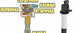
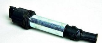
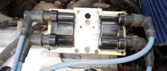
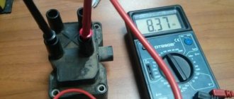
The car jerks, there is no traction, vibration is felt, or the engine is rough; all these are symptoms of improper operation of the individual ignition coil (IIC). Other signs of a faulty ignition coil are the presence of errors 0301, 0302, 0303 and 0304, indicating misfire in one of the cylinders. Let's look at a few simple ways to check the ignition coil with your own hands.
It is worth noting that the process of checking IKZ on modern Lada cars (XRAY, Vesta, Largus, Granta, Kalina and Priora) does not have significant differences. All actions are performed in the same way.
Visual inspection of the IKZ
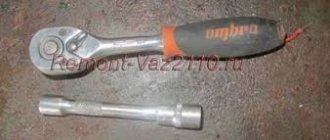
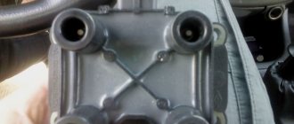
Remove the ignition coils from the engine using a 10mm or Torx E8 socket wrench (depending on the powertrain model). Carefully inspect the removed coils. There should be no cracks, damage to the rubber cap, melting or leakage of plastic. The spring located inside the coil must be in the correct position.
Connecting and replacing VAZ short circuit
The procedure for removing and installing the ignition coil on old VAZ models:
- First, disconnect the central high-voltage wire leading to the distributor (ignition distributor).
- Disconnect all power wires from the coil contacts. Since they are fastened with nuts, you will need an 8 wrench for this.
- If you don’t know which wires to connect to which connector later, it’s better to immediately remember or mark them somehow, so that later during installation you can connect them correctly.
- Unscrew the coil housing. It is attached to a clamp (clamp), which is pressed to the car body with two nuts.
- After the work has been done, you can remove the ignition coil and replace it if necessary.
Checking the ignition coil with a multimeter
Checking the voltage at the terminal block of the wires:
- Disconnect the block with wires from the ignition coil (on the H4M engine, to access the coils of cylinders 1 and 2, remove the intake pipe).
- Turn on the ignition and measure the voltage at terminal 3 of the wiring harness block (the numbering of the terminals is on the ignition coil).
- The voltage at the terminal must be at least 12 V. If it is less or absent, it means the battery is discharged, there is a fault in the power circuit, or the engine control unit (ECU) is faulty.
- Turn off the ignition.
How to check ignition coil resistance:
- We set the switch on the multimeter to the 200 Ohm position and close the probes (the instrument error will be displayed on the screen, which will need to be subtracted from the readings during testing).
- We check the primary winding of the ignition coil by connecting the probes of the device to the contacts.
- The resistance between pins 1 and 3 should be close to zero (about 1 ohm).
- The resistance between pins 1-2 and 2-3 should be high (tend to infinity).
- Set the switch on the multimeter to the 2000 kOhm (or 2 MOhm) position.
- We check the secondary winding of the coil by connecting the red probe to the spring inside the rubber cap, and the black probe to pin 2.
- For good contact, it is best to remove the rubber cap from the coil and connect the probe directly to the coil contact, having first cleaned it of deposits.
- The resistance should be about 300-400 kOhm.
Attention! The resistance of the secondary winding of the ignition coil is highly dependent on its temperature. Carry out the test when the coil is completely cool. Compare the resistance of all four ignition coils to each other. A faulty ignition coil can be identified by very different values, provided that all coils are from the same manufacturer.
The process is also shown in the video:
Checking the ignition coil yourself. Video instruction ZR:
Which reel to buy
Many car enthusiasts advise buying the cheapest devices. Why is that? It is believed that the coils burn primarily due to a poor-quality spark plug. Of course, it would be useful to make sure that all the spark plugs are in good working order, but even if there are no problems, but the coil still burns out, it is recommended to replace the spark plug in the cylinder where the malfunction occurred. At the same time, not all car owners are ready to trust the most budget reels, and such an opinion also has a right to life.
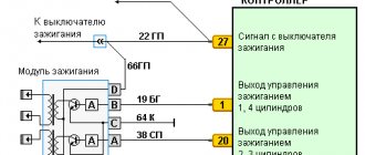
Ignition coils in the electronic circuit of Lada Priora
The ignition system on Priora differs from the usual classic scheme of carburetor models. On old cars there was one ignition coil, and the specific distribution of impulses to the spark plugs was carried out by a distributor, which still needed to be configured correctly. On injection models of cars with electric fuel injection, each cylinder has a personal > newspaper, a personal ignition coil, which supplies an impulse to the spark plug for its own cylinder.
The entire process is controlled by the ECU, an electrical on-board device, from which the signal goes directly to the short circuit. If you set a goal to correctly control the injection process and send a signal to an electronic impulse at the right time, the ECU uses data from the following sensors:
- DPK - taking into account the position of the engine crankshaft, it sends an impulse to the ECU;
- phase sensor - it talks about the position of the camshaft, masters call it a synchronization sensor;
- tachometer - from it a signal is sent to the ECU at what frequency the crankshaft rotates;
- Mass air flow sensor - through the use of measuring air flow through the air filter, determines the load on the engine at this point in time;
- DTOZH - determines the engine temperature;
- DT is a knock sensor, its readings affect the ignition timing.
Under standard criteria, according to the ECU signal, the cylinders operate in the subsequent cycle - 1 - 3 - 4 - 2.4.
In other words, the impulse to the spark arrives in those cylinders in which the compression cycle is completed, before the valve opens, fuel is injected and a discharge occurs, detonation occurs and the cycle continues.
Ignition of gasoline in the cylinders of an internal combustion engine occurs using a spark generated by the ignition system. The ignition module is the main element of the system, creating a spark on the spark plugs using high voltage. Each car manufacturer develops and produces its own original module, but the principle of its operation is the same for all devices. During operation, deviation from the specified parameters or breakdown of the ignition module negatively affects engine operation until the power unit fails.
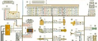
Instrument cluster block diagram
| № | Decoding |
| 1 | Electric power steering |
| 2 | Emergency gang control VAZ-2170 |
| 3 | Connection to oil pressure sensor |
| 4 | Parking brake indicator light |
| 5 | Electronic anti-theft device |
| 6 | Airbag control module |
| 7 | External lighting switch |
| 8 | Right turn signal indicator and doubler |
| 9 | Left turn signal indicator and backup |
| 10 | Engine control unit |
| 11 | Disabling the passenger's front airbag |
| 12 | Seat belt warning light |
| 13 | ABS brake system unit |
| 14 | Steering column switch button |
| 15 | Brake expansion tank indicator |
| 16 | ABS safety control module |
| 17 | Main beam headlight control unit |
| 18 | Shield backlight module |
| 19 | General disadvantage of the device |
| 20 | Constant positive battery terminals |
| 21 | Ignition switch contact |
| 22 | Fuel flow meter |
| 23, 24 | Steering wheel turn switches |
| 25,26 | Overboard temperature sensors |
| 27 | Fuel sensor VAZ-2170 |
| 28 | Speed sensor |
| 29 | Coolant temperature sensor |
| 30 | Tachometer signal |
| 31 | Shield diagnostics |
| 32 | Generator Regulator Relay Terminal |
Purpose and principle of operation
Ignition module VAZ 2110
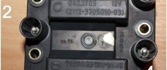
The ignition module of a modern car performs the function of generating high voltage to produce a spark at the spark plugs. It consists of two coils with a closed magnetic circuit and a two-channel switch. Sometimes the switch is made as a separate device, but in most cases it is combined with an electronic control unit for the engine. Externally, the modules differ in the number of wires in the connection connector: a module with a switch has 4 wires, and paired coils have 3.
The ignition module is controlled by the ECU, which supplies constant voltage in the form of low-voltage control signals to the windings of its coils at the right moment. The end of the signal is the beginning of the spark. Thanks to magnetic induction, at the moment of application, a high voltage is generated, creating a spark at the spark plug. The device is located in the engine compartment and can be easily identified by the high-voltage wires leading to the spark plugs.
Designations for the rear wiring harness of the VAZ Priora
The wiring harness, located in the passenger compartment and rear of the car, has the shape of a flexible barrel with branches on which contacts are installed with blocks for docking with consumer electrical appliances. The rear electrical circuit is also connected to lighting fixtures, locks, power windows, front and rear doors.
The pinout of tips and terminals looks like this:
| Contact no. | Decoding |
| 1 | Dashboard |
| 2 | Left rear door wiring harness block |
| 3 | Right front door wiring harness block |
| 4 | Used double-glazed windows and door locks |
| 5 | Left turn signal |
| 6 | Right turn signal |
| 7 | Interior lighting module |
| 8 | Handbrake warning lamp switch |
| 9 | Left side light |
| 10 | Right side lamp |
| 11 | Interior temperature sensor |
| 12 | Interior light switch in the left front door pillar |
| 13 | Interior light switch in the front right door pillar |
| 14 | Interior light switch in the right rear door pillar |
| 15 | Interior light switch in the left rear door pillar |
| 16 | Driver's door wiring harness |
| 17 | Right rear door wiring harness |
| 18 | Rear right speaker |
| 19 | Rear left speaker |
| 20 | Cigarette lighter |
| 21 | Fuel pump block |
| 22 | Trunk light switch |
| 23 | Rear window heating device |
| 24 | Trunk light |
| 25 | Additional brake light |
| 26 | Tailgate lock switch |
| 27 | License plate lamp harness |
| 28 | Right front door harness block |
| A 1-A4 | Grounding |
| XP, XP3 | Electrical package power controller connectors |
The rear wiring harness is marked 2170-3724210.
Signs of a malfunctioning ignition module
A malfunction of the ignition module is determined by the following symptoms:
- Difficulty starting a cold engine due to lack of spark on one or more spark plugs.
- Floating engine speed at idle is a situation in which the speed changes without any action on the part of the driver.
- Dips in power, which manifests itself during acceleration and driving up a long climb.
- Decrease in engine power.
- Cylinders 1-4 or 2-3 do not work (engine “troits”).
- Indication of the “Check Engine” indicator.
Signs of Engine Cylinder Failure
When driving, the engine begins to pull poorly. Work intermittently. However, at idle it seems to run smoothly. At speeds, if the neutral gear is engaged, there are no interruptions either. But as soon as you start moving, the engine shakes. Speed is gained pl
The electronic injection system is designed in this way. That it will compensate for the lack of operation of one cylinder. If you are supposed to maintain a certain number at idle. Even if the cylinder is not working, the electronic unit will give a command to increase the speed. And compensates for the loss of one cylinder. Also, as the speed increases, the injectors will begin to supply more fuel to the remaining cylinders than usual. The absence of one cylinder will not be noticeable. It's worth starting to move. The electronic control unit will also equalize engine speed by increasing the fuel supply to the working cylinders. But the loss of power will already be visible. Three cylinders are not four. The engine will choke. The sound of the engine will change. And there will be no pleasant acceleration like when 4 cylinders are running. Diagnostics involving a tester is expensive. Moreover, a faulty coil can be detected directly on the car.
Possible causes of ignition module malfunction
Despite the high reliability and durability of the ignition module, during operation it can fail, like any other mechanism. Among all possible causes of breakdowns, in 9 out of 10 cases the following occur and are diagnosed:
- Use of inappropriate components in the ignition system. High-voltage wires are selected based on the parameters of the module, since excessively high or low voltage creates malfunctions or burns out contacts.
- Defective or damaged parts, poor quality assembly. Defective components break down faster and damage other components or elements of the system. Practice shows that the selection of high-quality components and their periodic diagnostics allow the module to remain operational for a long time.
Removing and installing a coil on a Priora
The device in a Priora car may fail if damaged from the inside, resulting in “piercing” into the body. If the ignition coil is working properly, a spark should always jump between the electrodes of the spark plug. If this is not the case, you need to check the power supply and coil control circuits.
Part replacement in progress
All actions are carried out using a socket head at “10”. Disconnect the negative battery, press out the plastic fastener, disconnect the wiring harness block from the coil terminal, unscrew the bolt securing it to the cylinder head cover, and remove the coil from the spark plug block. When carrying out repair work, you need to remember that the Priora is equipped with a microprocessor-based high-energy ignition coil (HEC). High voltage ignition wires produce a voltage of 40 thousand volts. Anyone testing a coil needs to be extremely careful as there is a risk of electric shock. When performing an inspection, wearing rubber gloves will save you from possible negative consequences. You can use pliers with insulated handles.
Spark plugs need to be changed every 30 thousand kilometers. The manufacturer recommends a certain type of spark plug for the Lada Priora, but you can use any with a suitable combustion heat. The diameter of the part is 14 millimeters. After turning the candles out, the wells where they are located are thoroughly cleaned. This procedure is necessary to ensure that no dirt gets in after removing the parts. In preparation for winter, before installing spark plugs, you need to check the gap between the side and central electrodes. If the gap does not correspond to the values of 0.7-0.9 millimeters, adjustment must be made.
Despite the huge amount of criticism against the Lada Priora, this is one of the most popular cars that have come out of the AvtoVAZ assembly line in recent years. The Priora is equipped with a fairly successful engine with good dynamics, and the interior is very comfortable. And the maximum trim levels offer useful options. But at the same time, from time to time the car brings minor problems to its owners. One of the most popular malfunctions is that the Priora engine (16 valves) is tripping. The reasons for this phenomenon are quite unpleasant. And besides, the motor eventually overheats.
When the driver starts his car in the morning, the engine does not run smoothly as before, but intermittently. At this time, dull sounds are heard from the exhaust pipe. At the same time, a persistent and strong smell of unburned fuel is felt. Vibrations are constantly increasing, and this is fraught with cracks in the pillows. So
Checking the ignition module
Checking the ignition module for functionality is carried out in the following ways:
Replacing the ignition module with a known good one
1. The easiest way is to connect a known working module. In this case, the devices must be completely identical, the high-voltage wires are in good condition, and the reliability of the contacts has been checked.
Checking the contacts on the ignition module
2. Moving the module, which allows you to identify unreliable contacts. To do this, move the wire block and the module itself. If during exposure the engine reacts by changing its operation, then the cause of the problem lies in poor contact.
Checking the ICP with a spark gap
Procedure
:
- Disconnect the IKZ from the spark plug.
- Install a spark gap on the IKZ.
- Apply ground (from the battery terminal) to the spark gap using a wire.
- Turn the crankshaft with the starter.
- If there is a spark, then the IKZ is working.
Let us remind you that you can find a problem in engine operation by independently measuring the pressure in the fuel rail, or by checking the compression in the cylinders.
Keywords: Lada Vesta engine | lada xray engine | Lada Largus engine | Lada Granta engine | Lada Kalina engine | Lada Priora engine | ignition system for Lada Vesta | ignition system lada xray | ignition system Lada Largus | ignition system for Lada Granta | ignition system for Lada Kalina | ignition system for Lada Priora | universal article
0 0 0 0 1 0
Share on social networks:
Lighting control unit diagram
| G, 56b | To the gear motor for adjusting headlights |
| 58b | Output to backlight sources |
| 31 | Mass (ground) |
| Xz | +12 volts (from terminal 15 of the ignition switch) |
| 56 | To the relay for switching high and low headlights |
| 1,3 | From rear and front fog lights |
| 2,4 | To the rear and front fog lamp relays |
| 58 | For lamps of Lada Priora dimensions |
| 30 | +12 V from terminal No. 30 of the ignition switch |
