December 17, 2020 Lada.Online 18 533 19
Good halogen car lamps can cost more than 1 thousand rubles. It will be a shame if they quickly burn out. To extend their service life, it is enough to implement their smooth ignition. After all, incandescent lamps most often burn out the moment they are turned on. You can modify the design yourself in two different ways.
Relay for running lights 12, 24V DRL unit DRL low, high
News Main Hyundai News Others. Reviews Reviews Solaris new Reviews Solaris Operation Solaris new Solaris Anti-theft systems. Manuals Maintenance regulations Repair and maintenance manual new. Name: Password.
We recommend that you register or log into your account in order to fully use all available tools for purchasing, selling and communicating on the site. In all sections Joint purchases and orders Children's goods Children's clothing and shoes Women's clothing and shoes Men's clothing and shoes Beauty and care Products for home, recreation, holidays Stationery, books, art Services, work Animals, plants, accessories Other Buy, exchange, give away , demand.
What do you need
To properly assemble a soft ignition module for LEDs, you will need a set of the following tools and materials:
- Soldering station and set of consumables (solder, flux, etc.).
- A fragment of a textolite sheet for creating a board.
- Housing for placing components.
- The necessary semiconductor elements are transistors, resistors, capacitors, diodes, ice crystals.
However, before you start making your own soft start/damping unit for LEDs, you need to familiarize yourself with the principle of its operation.
The image shows a diagram of the simplest model of the device:
It has three working elements:
- Resistor (R).
- Capacitor module (C).
- LED (HL).
A resistor-capacitor circuit based on the RC delay principle essentially controls the ignition parameters. So, the greater the value of resistance and capacitance, the longer the period or the smoother the switching on of the ice element occurs, and vice versa.
Schemes for smooth switching on and off of LEDs
There is no point in disassembling cumbersome circuits, because... Most problems can be solved by simple devices operating on elementary circuits. Let's consider one of these schemes for smoothly turning on and off LEDs. Despite its simplicity, it has a number of advantages, high reliability and low cost.
Consists of the following parts:
- VT1 – field effect transistor IRF540;
- C1 – capacitor with a capacity of 220 mF and a voltage of 16V;
- R1, R2, R3 – resistors with a nominal value of 10, 22, 40 kOm, respectively;
- LED – light-emitting diode.
Operates from a voltage of 12 Volts according to the following algorithm:
- When the circuit is connected to the power circuit, current flows through R2.
- At this time, C1 gains capacity (charges), which ensures the gradual opening of the field switch VT
- Increasing gate current (pin 1) flows through R1, and causes the field drain VT to gradually open
- The current goes to the source of the same field switch VT1 and then to the LED.
- The LED gradually increases its light emission.
The LED dims when the power is removed. The principle is the opposite. After turning off the power, capacitor C1 begins to gradually transfer its capacitance to resistances R1 and R2.
The main element is the field-effect n-channel MOSFET transistor IRF540, all other semiconductor devices play an auxiliary role (piping). It is worth noting its important characteristics:
- drain current: up to 23 Amperes;
- polarity: n;
- drain-source voltage: 100 Volts.
More detailed information, including current-voltage characteristics, can be found on the manufacturer’s website in the datasheet.
Improved version with the ability to customize the time
The option discussed above assumes the use of a device without the ability to adjust the ignition time and LED attenuation. And sometimes it is necessary. To implement it, you just need to supplement the circuit with several elements, namely R4, R5 - adjustable resistances. They are designed to implement the function of adjusting the time of complete switching on and switching off the load.
The considered schemes of smooth ignition and decay are perfect for implementing designer lighting in a car (trunk, doors, foot area of front passengers).
Another popular scheme
The second most popular scheme for smoothly turning on and off LEDs is very similar to the two discussed, but they are very different in operating principle. Switching on is controlled by minus.
Differences between the scheme and those discussed earlier. The main difference is a different transistor. The field switch must be replaced with a p-channel one (the markings are shown in the diagram below). You need to “turn over” the capacitor, now the plus of the capacitor will go to the source of the transistor. Do not forget, the modified version has power with reverse polarity.
Minus control
The above translated diagrams are perfect for use in a car. However, the complexity of some electrical circuits lies in the fact that some of the contacts are connected to the positive, and some to the negative (common wire or body). To control the above circuit by minus power, it needs to be slightly modified. The transistor needs to be replaced with a p-channel one, for example IRF9540N. Connect the negative terminal of the capacitor to the common point of three resistors, and connect the positive terminal to the source of VT1. The modified circuit will have power with reverse polarity, and the control positive contact will be replaced by a negative one.
The diagram for this ignition was made based on the recording of a fellow on board. I'm good with soldering irons, but I'm not good with circuits...
Let's return to the diagram; the diagram is very popular on the Internet, therefore it has been tested more than once, but there is one thing - it has one thing that I don’t need - control by plus from the ignition switch and dimensions. I don’t want to crash into the ignition, I just did it by throwing out the same control element from the circuit and setting the resistor that is responsible for the ignition speed to be adjustable (R2* - correction nominal 100 kOhm, ).
DIY crafts for car enthusiasts
Simple electrical tuning of a car using LEDs that flash on and off smoothly. Domestic cars are produced with the average consumer in mind. Many car enthusiasts are not happy with this, so they are trying to improve this car. First of all, this concerns the lighting of the dashboard and interior.
You can assemble a device for continuously adjusting the LED backlight yourself. It’s easy to find an interesting diagram on the Internet.
Without any doubt, the simplest and most reliable circuit is a field-effect transistor. Let's take a closer look.
Instrument lighting.
When they talk about upgrading the dashboard, they mean electrical tuning, which allows you to make it unique using LEDs.
A little about the operation of the circuit.....:
After turning on the ignition, the circuit is powered with a voltage of +12 V and switches to standby mode.
When the dimensions are turned on, the control voltage +12 V is supplied to the KT 503 transistor through a chain consisting of diode D2 and resistor R1. The transistor opens. Electrolytic capacitor C1 is charging.
A smoothly increasing voltage is supplied to field-effect transistor VT1. It opens smoothly and gradually increases the output voltage to the LEDs. They burn smoothly.
When the dimensions are turned off, the control voltage is removed and the transistor KT 503 is closed. The electrolytic capacitor C1 is smoothly discharged through R3. Consequently, the voltage across transistor VT1 decreases, and hence the output voltage.
As the capacitor discharges, the LEDs go out.
When the capacitor is completely discharged, the circuit again goes into standby mode, in which almost no current is consumed.
The load of transistor VT1 can be an LED assembly or an LED strip. The IRF 9540 transistor can handle loads up to 140 W.
The following adjustments are allowed in the diagram:
Interior lighting
Smooth interior lighting has its advantages:
The LED backlight turns on after the limit switches on the doors are activated.
The diagram looks like:
Unlike the previous circuit, the control voltage here is –12 V coming from the limit switches.
Compared to the previous one, individual elements have been removed from the circuit: transistor KT 503, diode D2 and resistor R1, but the operating principle is the same.
Schemes in .lay format -
Circuit assembly
The circuit elements are placed on a printed circuit board, which is manufactured in a certain sequence:
1. Prepare a textolite plate. Its size depends on the number of elements and their location. The cut plate must be treated with fine sandpaper and degreased.
2. Using the Sprint Layout program, draw the future board. To print the picture, a laser printer is used in high definition and image quality mode.
The program selects a mode in which only the layer with tracks without markings will be printed. The drawing is printed onto a glossy magazine page or photo paper.
3. Apply the printout to the heated PCB plate and press it with a hot iron. We hold the iron for several minutes.
4. After cooling, lower the plate into cold water and remove the paper from the surface.
5. In the prepared ferric chloride, lower the plate attached to a piece of polystyrene foam. During etching, you can remove and monitor the board.
6. Wash the etched plate in water and clean the tracks with solvent or sandpaper.
7. Drill holes in the finished board for mounting the elements. 0.6 mm drills are used.
8. We service the board. The most affordable way is to coat the board with flux with a brush and tin it with a soldering iron.
It is important not to overheat the tracks so that they do not peel off
9. Install the circuit elements on the board and solder them.
10. At the end of the work, it is necessary to clean the board from any remaining flux. A clean board will have no shorts between tracks.
As a result of the consideration, it should be noted that the described schemes are successfully used not only for electrical tuning of a car. They are often used with various devices that have +12 V power.
Author; Arseny St. Petersburg, Russia
Popular;
- Delay for turning on the low beam or DRL for 8-10 seconds, diagram
- Simple electronic turn signal relay for lamps or LEDs, diagram
- Simple voltage regulator on LM317, circuit
- Smooth on and off DRL
- Converter for charging capacitors
- Smooth ignition of headlights or LEDs on a microcontroller
- Simple driver for LEDs
- Battery protection circuit from deep discharge
Tags: lighting, ceiling light, soft start
Comments 43
Tell me, is a bipolar transistor suitable here (KT837D)?
did you draw a signet in the sprint? if so, can you send it to me?
I'll look at it on my home computer in the evening, and if I have any left, I'll post it.
as a friendly criticism: 1. instead of a nickname, it would be better to leave a polygon for heat dissipation, and in general route the board so that there is no need to etch, but it would be possible to draw out isolated areas with a craft knife 2. do not solder the wires to the board , and connect it with a connector - when you want to improve the device, you could simply replace it
The heat dissipation is clearly unnecessary... The transistor is powerful, but the diodes in the lampshade consume just a little bit. It is higher than the ambient temperature and does not heat up. Regarding marking the board with a stationery knife - well, I don’t like this kind of collective farm. I’d rather spend an extra half an hour or an hour, but I’ll do everything beautifully. The connector is located, but not on the board itself, but on a five-centimeter piece of wire. This makes it more convenient to place the device under the ceiling - first stick it in place as it should, and then connect the wires.
and how did you etch the board? How did you apply it to the textile?
The tracks were applied using photoresist. Etched in a solution of hydrogen peroxide, salt and citric acid.
I remember, I used to paint paths with varnish... I etched them in ferric chloride))) don’t they do that anymore?))) Psst I’m behind...
Well, probably no one paints with varnish now, it’s easier to do it with the same LUT. But I myself used ferric chloride until recently, until I learned about the method with hydrogen peroxide - it’s easier to get, and cheaper, and it doesn’t stain everything around)))
and how did you etch the board? How did you apply it to the textile?
TextOlit. Actually, it’s fiberglass.
ok, that’s it, I was being clever...
If you like being illiterate, stay...
Do you often use textolite? since there was fiberglass here... I think it’s already clear what kind of material it is... there’s a mistake in the name - yes, I remember it correctly. But. I don’t think it’s a mistake to simply call the material for boards PCB. I think many people say this so as not to lengthen an already understandable word. It's like always adding a lead-acid battery to a car. I don't think you're adding either. fiberglass = textolite. the essence of what we are talking about does not change at all.
The fact is that PCB is a fabric impregnated with glue. It is brown in color. www.ru.all.biz/img/ru/catalog/2068698.jpeg It is not metallized and is not used for the production of printed circuit boards.
And fiberglass is fiberglass impregnated with epoxy resin; it is light yellow in color. And the properties of the materials are very different.
Getinax is also used as a dielectric for printed circuit boards - this is paper impregnated with glue. Also, by the way, brown.
Getinax is often used in household appliances (previously, only getinax was used). Fiberglass began to replace it a couple of decades ago.
Yes, I’ve been doing electronics for a long time, 40 years already. I designed and manufactured my first printed circuit board at the age of 12, i.e. in 1982...
Smooth turning on and off of LEDs: ignition circuits
In some cases, it is necessary to implement a circuit for smoothly turning on or off an LED. This solution is especially in demand in organizing design solutions.
To implement the plan, there are two solutions. The first is to buy a ready-made ignition unit in a store. The second is making a block with your own hands.
In the article, we will find out why it is worth resorting to the second option, and also analyze the most popular schemes.
Buy or make it yourself?
If you need it urgently or don’t have the desire or time to assemble a block for smooth switching on of LEDs with your own hands, then you can buy a ready-made device in a store. The only negative is the price. The cost of some products, depending on the parameters and manufacturer, can exceed several times the cost of a device made by yourself.
If you have time and especially desire, then you should pay attention to long-developed and time-tested schemes for smoothly turning on and off LEDs
What do you need
In order to assemble a circuit for smooth ignition of LEDs, first of all, you will need a small set of radio amateurs, both skills and tools:
- soldering iron and solder;
- textolite for the board;
- body of the future device;
- a set of semiconductor devices (resistors, transistors, capacitors, LEDs, diodes, etc.);
- desire and time;
As you can see from the list, nothing special or complicated is required.
The Basics of Soft Start
Let's start with the basics and remember what an RC circuit is and how it is related to the smooth ignition and decay of the LED. Look at the diagram.
It contains only three components:
- R – resistor;
- C – capacitor;
- HL1 – backlight (LED).
The first two components make up the RC circuit (the product of resistance and capacitance). Increasing the resistance R and capacitance C of the capacitor increases the ignition time of the LED. When decreasing, the opposite is true.
We will not delve into the basics of electronics and consider how physical processes (more precisely, current) occur in this circuit. It is enough to know that it underlies the operation of all smooth ignition and extinction devices.
The considered principle of RC delay underlies all solutions for smooth turning on and off of LEDs.
Schemes for smooth switching on and off of LEDs
There is no point in disassembling cumbersome circuits, because... Most problems can be solved by simple devices operating on elementary circuits. Let's consider one of these schemes for smoothly turning on and off LEDs. Despite its simplicity, it has a number of advantages, high reliability and low cost.
Consists of the following parts:
- VT1 – field effect transistor IRF540;
- C1 – capacitor with a capacity of 220 mF and a voltage of 16V;
- R1, R2, R3 – resistors with a nominal value of 10, 22, 40 kOm, respectively;
- LED – light-emitting diode.
Operates from a voltage of 12 Volts according to the following algorithm:
- When the circuit is connected to the power circuit, current flows through R2.
- At this time, C1 gains capacity (charges), which ensures the gradual opening of the field switch VT
- Increasing gate current (pin 1) flows through R1, and causes the field drain VT to gradually open
- The current goes to the source of the same field switch VT1 and then to the LED.
- The LED gradually increases its light emission.
Automatic headlight switch with delay | Homemade catalog
To comply with the requirements of the new traffic rules changes, you should turn on the low beams on your vehicle when driving on a country highway, even during the day. In the city, you also need to remember to turn on the lights in conditions of poor visibility.
Except for compulsory cases imposed by law, each driver has the right to decide when to protect himself and others. It is recommended to turn on the lights on your car when driving through a section of road near kindergartens, schools, and playgrounds. Any vehicle, especially a gray, black, white body color, becomes many times more noticeable when the head lights are turned on.
On a clear day, when the sun makes you close your eyes, there is no reason to reach for the headlight switch. It’s another matter when automation remembers important things for you. And in order for the automatic light switch circuit to only please you and not be thrown out of the car soon, several conditions must be met:
- The headlights should light up with a delay of 10–15 seconds after starting the engine. This is necessary so that there is no large voltage drop when a powerful lighting load and starter are operating simultaneously.
- The headlights should turn off with a delay (the time must be selected individually) after the engine is turned off. This is important so that the lights do not click again if you need to turn off the car near a crossing or for quick refueling. Homemade DRL control unit .
- Electronics must operate at relatively high currents . So it is necessary that neither humidity nor temperature, which varies widely inside the car, greatly influence the operation of the elements of the automatic headlight switching circuit.
- So, this simple scheme has been tested for a long time and is successfully used:
- Instead of the above elements, you can use others:
- The K561LA7 microcircuit can be replaced with K561LE5, CD4001, CD4011. The input logic does not matter at all, since only the inversion of the outputs is used.
- Diodes KD522 - on KD521, KD105, 1N4148.
- Transistor KT815A - on KT817, KT604.
- All capacitors must be selected for a voltage of 25 V.
Well, or try another, easier to assemble, smooth ignition device .
Power connection
- It is important to connect the anode of the VD1 diode to the output of the ACC ignition switch, from which voltage is supplied to the ignition or injector switching circuit. But not to the starter switching terminal, since in this case the headlights either will not turn on at all or will go out immediately after starting the engine.
- The microcircuit is powered directly from the battery (+Acc, -Acc), and not from a circuit that is switched off.
- The open contacts of a standard automotive relay K1 are connected to the break in the wire running from the power circuit to the low beam contacts of the headlights.
Setting up the scheme
The delay time for turning on the headlights can be set to more than 10–15 seconds by selecting resistor R2 with a higher resistance.
If desired, the delay time for turning off the headlights can be reduced (according to this scheme it is 5–10 minutes) by installing resistor R1 of lower resistance.
Changing the delay time by replacing capacitor C1 is undesirable, since such an element with an unusually high capacitance (used in the circuit at 2200 μF) is necessary to deliver a relatively high current.
If you use a small capacitor in the driving circuit, you would have to install megaohm resistors R1, R2, which are not stable due to high leakage currents.
Conversion to 24 volts
- Take all capacitors of the same capacity, but for a voltage of 50 V.
- Change resistor R3 to another 300 Ohm.
- It is advisable to install a 5 volt zener diode between pins 7 and 14 of the microcircuit.
- And don’t forget to replace the relay with a 24-volt one.
Source: https://volt-index.ru/electronika-dlya-nachinayushih/interesnoe/avtomaticheskiy-vklyuchatel-sveta-far-s-zaderzhkoy.html
DIY connection
First of all, it must be said that having disassembled the dimmer, everyone can understand that its connection is no more complicated than a regular switch.
Let's create step-by-step instructions, using which everyone can get the desired result:
The first and most important step is to disconnect the power from the outlet.
This is a safety measure, because you need to work with exposed wires, and getting hit by 220V is not the most pleasant thing.
Loosen the screws on the terminals.
Next, we connect 2 wires of the switch to the wires from the old switch (it is important not to forget and observe the polarity, otherwise, at best, everything will have to be redone).
We remove the top frame and install the device in a specially designated place in the wall.
Screw in the screws of the mounting tabs.
We fasten the top frame (box).
Automatic switching on of headlights upon ignition
In order to organize such operation of the lighting elements, it is necessary to connect them to the ignition power source, and as many know, some devices can be connected at any position of the ignition switch, while others begin to function only when the ignition is already on. Based on this, the most convenient place to connect the headlights is the heater switch button (the rightmost switch block).
For this scheme you will need:
- any standard five-pin relay;
- diode;
- wires.
Next, we need:
- Remove the size switch (switch block on the leftmost side).
- Disconnect the positive wire from the key block responsible for the low beam operation (usually this is a green double wire) and connect it to the relay.
- You need to insert an additional wire into the positive wire that goes to the heater switch and also connect it to the relay.
- Connect the wire that powers the headlights to the relay.
- Throw the wiring to minus (to the body).
Other reasons why LED lamps burn out
You have reduced the number of harmful factors to a minimum, but the lamps still fail. Why is this happening? There are two more reasons:
- turning on and off too often;
- bad power supply.
Frequently turning lamps on and off
When the light is turned on, a current surge occurs through the smoothing capacitor. Therefore, there is a danger of blowing the fuse or the current-carrying path. To avoid this problem, you do not need to constantly switch the lighting. LED lamps are economical, and an extra hour of work will not hit your budget.
Voltage transformer
Lack of protection against voltage surges is the main problem with lamps in the budget price segment. The driver provides a stable current for LED operation. Often it is this that fails for the reasons described above. Check the presence of voltage at the output of the power supply, as well as the integrity of all LEDs.
For low-voltage lamps (12 V), electronic transformers are also used. If none of your lamps are on, check that one first. By the way, it’s not at all difficult to assemble one from several burnt out ones.
High-quality light is very important for your health and vision, but cheap products are a blow to your budget. Lamps often burn out, pulsation coefficient, and color rendering quality do not meet standards. Monitor the condition of your lamps, switches and wiring to avoid premature “death” of lamps. Then you will avoid unnecessary expenses.
Overview of the main options and their features
We will look at how to automatically turn on the low beam in two ways, each of them has its own characteristics, and the choice ultimately depends on you.
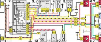
Domestic manufacturers suggest using a special relay as a solution to the problem, its marking is 719.3777-01, with its help you can automatically turn on the low beam and side lights.
The following can be said about this option:
- The system is suitable for VAZs from the 4th to the 15th model, for example, the relay is installed for fog and regular headlights in the VAZ 2110, GAZ, UAZ and others, in which the low beam winding of the relay has a permanent connection to ground;
- The headlights light up approximately 5 seconds after the engine starts, which is very convenient, since, firstly, it makes it easier to start the engine, secondly, the load on the battery is significantly reduced, and thirdly, the life of the lamps increases;
- The lights turn off when the ignition is turned off, which is also very convenient, because now you won’t leave the car with the headlights on;
- If necessary, you can always turn off the light manually; to do this, the switch is flipped to the “low beam” position, and then placed in the “off” position.
Now let’s look at how to implement automatic switching on of low beam headlights with your own hands; the work is carried out in the following sequence:
First, you need to install a new unit instead of the low beam relay, and if you use mini-relays, you will need a special adapter, which should also be included in the kit, the whole process is as simple as possible and will not take much time;
By going through this process, you will get a convenient and reliable system that will prevent many problems.
Schemes for smooth switching on and off of LEDs
There are two popular and self-manufacturing options for soft ignition circuits for LEDs:
- The simplest.
- With function for setting the start period.
Let's consider what elements they consist of, what is the algorithm of their operation and the main features.
A simple scheme for smoothly turning on and off LEDs
Only at first glance, the smooth ignition diagram presented below may seem simplified. In fact, it is very reliable, inexpensive and has many advantages.
It is based on the following components:
- IRF540 is a field-effect transistor (VT1).
- Capacitive capacitor 220 mF, rated at 16 volts (C1).
- A chain of resistors of 12, 22 and 40 kiloOhms (R1, R2, R3).
- Led crystal.
The device operates from a 12 V DC power supply according to the following principle:
- When the circuit is energized, current begins to flow through block R2.
- Thanks to this, element C1 is gradually charged (the capacity rating increases), which in turn contributes to the slow opening of the VT module.
- The increasing potential at pin 1 (field gate) provokes the flow of current through R1, which contributes to the gradual opening of pin 2 (VT drain).
- As a result, the current passes to the source of the field unit and to the load and ensures smooth ignition of the LED.
The process of extinction of the ice element follows the reverse principle - after removing the power (opening the “control plus”). In this case, the capacitor module, gradually discharging, transfers the capacitance potential to blocks R1 and R2. The speed of the process is regulated by the rating of the element R3.
The main element in the smooth ignition system for LEDs is the MOSFET IRF540 n-channel field-effect transistor (as an option, you can use the Russian model KP540).
The remaining components relate to the harness and are of secondary importance. Therefore, it would be useful to present its main parameters here:
- Drain current is within 23A.
- The polarity value is n.
- Drain-source voltage rating is 100V.
Improved version with the ability to customize the time
Often there is a need to change the period of smooth ignition of LEDs. The scheme discussed above does not provide such an opportunity. Therefore, two more semiconductor components need to be introduced into it - R4 and R5. With their help, you can set resistance parameters and thereby control the ignition speed of the diodes.
The above versions of the circuits assume control by plus, but in some situations control by minus is required. In this case, the system will have reverse polarity. Therefore, you need to put a capacitor in it in reverse - so that the positive charge goes to the transistor source. In addition, it is necessary to replace the transistor itself; now it must be a p-channel type, for example, IRF9540N.
Features of connecting LEDs
In most cases, plug-in LEDs require current limiting using resistors. But sometimes it is quite possible to do without them. For example, flashlights, keychains and other souvenirs with LED bulbs are powered by directly connected batteries. In these cases, the current limitation occurs due to the internal resistance of the battery. Its power is so low that it is simply not enough to burn the lighting elements.
However, if connected incorrectly, these light sources burn out very quickly. A rapid drop in the brightness of the glow is observed when normal current begins to act on them. The LED continues to glow, but it can no longer fully perform its functions. Such situations occur when there is no limiting resistor. When power is applied, the lamp fails in just a few minutes.
One of the options for incorrect connection to a 12-volt network is to increase the number of LEDs in the circuits of more powerful and complex devices. In this case, they are connected in series, based on the battery resistance. However, if one or more light bulbs burn out, the entire device fails.
There are several ways to connect 12 volt LEDs, the circuit of which allows you to avoid breakdowns. You can connect one resistor, although this does not guarantee stable operation of the device. This is due to significant differences in semiconductor devices, despite the fact that they may be from the same batch. They have their own technical characteristics, differing in current and voltage. If the current exceeds the rated value, one of the LEDs may burn out, after which the remaining light bulbs will also fail very quickly.
Driver repair
First of all, check the fuse, if there is one. The device should show zero resistance. This can be done without removing the fuse from the board. Did the device show infinitely high resistance? Replace the fuse and plug in the lamp to test. Is it glowing? The renovation is complete. If the fuse is OK, we continue the repair. Check the diode bridge. You can find out in detail how to do this here.
Is the diode bridge working? Then unsolder the smoothing electrolytic capacitor and ring it. If the capacitor is working properly, then at the initial moment of continuity the multimeter will show a small resistance, which will grow before our eyes until it goes to infinity.
If the driver is simple, as often happens, then all these manipulations will certainly lead to success and completion of the repair. If the driver is more complex, then all you can do is ring the remaining electrolytic capacitors and diodes. It is easier to completely unsolder capacitors; only one terminal of a diode can be unsoldered. To make it lose contact with the board, it is enough to lift the device with a needle or tweezers.
If everything is in order here, then, alas, for further more complex repairs you will have to use the help of a qualified electronics engineer.
Main conclusions
Smooth ignition of LED-based lamps is popular in automatic lighting. In addition, the slow switching on of the ice elements allows you to extend their service life, regardless of the installation location. You can buy such a device or make it yourself. In the latter case, it will cost much less. For assembly you will need the following materials and tools:
- Soldering iron with soldering accessories.
- The basis for the board, for example, a piece of PCB.
- Housing for fastening elements.
- Resistors, transistors, diodes, capacitors and other semiconductor elements.
The mechanism of the soft ignition device for LEDs works on the principle of delay that occurs in the resistor-capacitor circuit.
In this case, there are two main schemes - the simplest and with the ability to adjust the ignition time. The latter differs from the first by the presence of two resistors with controlled resistance. The higher its value, the longer the slow start period, and vice versa. No tags for this post.
Algorithms for the operation of the circuit
Slow heating when first turned on
The following happens:
• first 3 sec. The glow of the lamps gradually increases up to 30% due to PWM operation; • level of heat achieved 2 sec. maintained unchanged to warm up the lamps; • in the next 3 sec. smoothly increases to the level of 80% and the headlights provide a satisfactory level of illumination; • for the last 4 seconds. 100% power is achieved