The standard Chevrolet Niva speed sensor is a separate module designed to transmit a signal from the gearbox output shaft to the speedometer. The device is simple - the functionality of the system is limited to only one option. The main advantage of the electronic system is increased accuracy. Such a speedometer has a minimal error, which increases traffic safety and eliminates the appearance of controversial fines for speeding.
This performance means that over a range of 1000 meters, the sensor generates more than 6000 pulses, which allows it to maintain extreme accuracy.
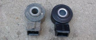
On the Chevy Niva, the sensitive sensor is made entirely of plastic; the contact chip is also quite sensitive. Therefore, care will need to be taken during repairs.
Where is the speed sensor located on a Chevrolet Niva
The DS sits directly on the gearbox housing. It is noteworthy that the location of the device on machines of 2008 and 2022 has not changed. The stability of the structure indicates the correct placement of the device. The module is covered by body panels and the gearbox housing, which makes it inaccessible to obstacles and sharp elements that could damage the sensor.
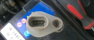
You can see what the module looks like in the photo.
Phase sensor - DF
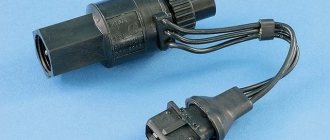
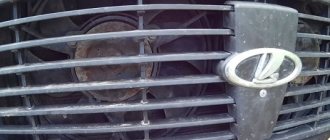
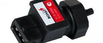
It's also a camshaft sensor. The VAZ phase sensor is designed to determine the angular position of the camshaft. The main function is that when the engine is running, the phase sensor provides a pulse signal to the controller synchronizing fuel injection with the opening of the intake valves. Failure of the phase sensor switches the fuel supply to pairwise-parallel mode, which leads to a slight (up to 10%) increase in fuel consumption. And I’ll also add this “miracle of nature” is a headache and a source of a lot of errors, for example the famous 0301, 0302.... In my humble opinion, this is the same disgusting and abomination as the old-style hydraulic compensators. But what has grown has grown. (How to get rid of it forever, lambda, roll sensor - will be written in the article about chiptuning). The only normal manufacturer of this sensor is Avtovazagregat. The logo is visible in the photo.
The article was written for the NivaFAQ website.
Goal: share knowledge and experience gained with forum members https://www.niva4x4.ru.
It is known that injection Nivas have a speed sensor, the signals from which are transmitted to the ECU and which is located somewhere on the transfer case. There is not much information with details on this matter, so I decided to make a photo report.
The photo quality is not very good, I took it with my phone because... Naturally, I forgot my camera at home.
First, the symptoms: the ECU never gave a DC error, only an XX high speed error. I had problems with IAC, I described this in another article. However, it turns out that if the ECU produces errors that it considers to be primary, then secondary ones, even if they exist, are simply not issued. Therefore, I did not know about the DS error, because having repaired the IAC, I calmed down with joy. But sometimes, especially when coasting, “Jackie-chan” still got out - it’s summer, there was no time to deal with it. It also happened, especially in the heat, that the idle speed would hang high and stay there. If you gasp, they will fall, but they may not fall. Removing the battery terminal helps.
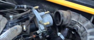
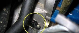
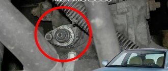
Then the speedometer cut out. Everything was fine in the tidy - I went to look down. And this is what I saw:
On carburetor Nivas, only the speedometer drive is located on this cover (on the right). And on the injection there is also a speed sensor (on the left).
I don’t know how it is on other Nivas, but on my DS it was installed in a very cunning way. In this cover on the right there is a boss on which there is a thread for the speedometer drive. What prevented VAZ designers from doing the same is unclear. I have a hole in the lid on the left into which an aluminum bushing adapter is inserted and then the DS is screwed onto this adapter.
In the photo above you can see that the sensor on the left is wired to the speedometer drive. This is because this aluminum adapter is quite easy to pull out of the cover. The tension is very small. And so that he wouldn’t leave and get lost, they tied him up. I don’t know if it should have been like this from the factory or if it was once broken off and restored this way.
Operating principle and design features
The standard Shnivy speedometer sensor is a hall sensor enclosed in a plastic housing. The element has a specific design that allows it to read the number of shaft revolutions.
The next stage of the device's operation is signal processing. The computer counts the revolutions of the box for a certain period of time and transmits the data to the speedometer display.
Operation of the electromechanical speedometer
Devices with a similar operating principle are more popular, especially in the domestic automotive industry. Their configurations are different. The essence of the work remains unchanged and is similar to mechanical analogs; there is a speed sensor and the counting unit itself. The only difference is the implementation of the functions.
The following sensors are used in electromechanical devices:
- conventional gears connected to the secondary shaft of the efficiency and drive the left wheel;
- pulse, operating on the basis of the Hall effect;
- induction;
- combined.
High-speed units can be modified, magnetic induction units with indication of magnetoelectric devices. They work in conjunction with a gear vehicle speed sensor. Counting units with an electronic unit base and an indication provided using a milliammeter are considered accurate. They operate in conjunction with combined and electronic sensors.
In modified systems, measurement is provided using a special microcircuit or sensor that sets a signal and converts it by an electronic unit, transmitting readings to devices. The magnitude of the current is proportional to the speed of the car, and the arrow of the device is in this dependence. In high-speed nodes, the block processes the signal received by the speed sensor. The principle of indication remains the same.
Connection diagram
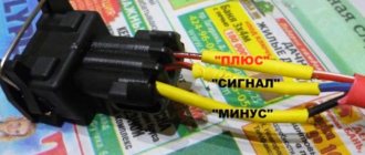
The Shnivy sensor connector itself is a three-pin connector, where:
- red – plus;
- black – minus;
- blue – signal.
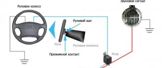
The electrical diagram of the element will tell you how the wiring is connected to the speedometer.
Skipping the details and complexity of the speedometer drive pinout, you should focus on connecting the sensor itself. There are three wires here.
- Cable number 1 is a plus, goes to the brake fluid sensor. To maintain constant nutrition.
- The second wire is connected to the speedometer and is responsible for transmitting the signal.
- The third one is black. The cable is responsible for the minus and is connected to another similar wire, or screwed onto the car body, directly at the installation site.
Basic elements of the electrical system
The vehicle's on-board network is designed so that all components and assemblies function smoothly, and control is as comfortable as possible. According to international standards, the voltage is 12V to be compatible with most consumers.
The circuit itself is single-wire. In practice, this means that the “negative” terminal is connected to the car body, and each individual device is powered by a “positive” wire. This greatly simplifies the routing of wires along the body and reduces the number of wires required. It also reduces the likelihood of cable damage and, as a result, a short circuit.
Fuse
They are located directly in the mounting block.
According to the pinout of the fuse links, there is no separate element for the sensor. The on-board circuit only has a fuse responsible for part of the wiring. This is argued by the fact that the element does not have a separate power supply system - the positive conductor is connected directly to the DVTZh. The fault should be looked for directly from fuse F19.
Causes of breakdowns
There are a number of possible reasons for module failure. The most popular of them are described below.
- Mechanical damage. A similar problem occurs among users who operate the vehicle in off-road conditions. Protruding road surface elements, branches and stones can damage the plastic housing or break wires.
- Moisture ingress. Over time, the insulation of wires and blocks can dry out. The winding cracks and allows water to enter the system, which can cause a short circuit.
- System failure. During power surges, the on-board computer may malfunction. Errors within the module prevent data from being read from the device correctly.
A broken dashboard is the first thing you think about.
The main problem that most drivers think about when there is no speedometer and odometer reading is the breakdown of the dashboard itself. Perhaps some plastic gears in the speedometer, which are so unreliable, have broken, and the connector has come loose from the odometer. There can indeed be a lot of reasons for problems; each reason has its own characteristic manifestation. But often the culprit for the lack of speedometer reading is not the dashboard itself. This element can break for several important reasons:
- a problem that has appeared for a long time, which has not found a normal solution and a sufficiently high-quality diagnosis;
- simultaneously with the cessation of displaying the speed and kilometers traveled, the dashboard backlight also disappeared;
- the wires from old age and difficult operating conditions have become frayed and shorted, creating a local short circuit;
- water got into the instrument panel, the electronic mechanism did not withstand such a test and stopped functioning normally;
- during operation of the car, a certain sound emanates from the instrument panel, similar to a buzzing sound (gears are broken);
- On old mechanical speedometers, the fastening of the cable going to the panel from the gearbox often fails.
Such problems all have a fairly simple solution, but often car owners decide to replace at least the speedometer, or at most the entire dashboard. This is very expensive even for an old domestic car, since the devices have always cost a lot. It is interesting that after going through all the steps of replacing and installing a new speedometer or even a factory-made instrument panel, just removed from the factory packaging, you will not always get the desired results. The expected speedometer operation may not begin for many reasons, including the following:
Symptoms of a problem
Simply observing the car's behavior will help you understand that the speedometer sensor is not working. Typically the symptoms of a breakdown are factors.
- The speedometer needle jumps, jerks or does not respond. This is due to the complete failure of the device and the need for its immediate replacement.
- Increased fuel consumption. Part of the system is interfaced with the ECU, therefore, the remaining sensors will also act up.
- The speedometer is reporting incorrect data. If a motorist sees that the actual speed of the car differs significantly from the measured one, this is a sign of a device failure.
- 4. Separately, instability of idle speed should be considered. The device is also responsible for the operation of the motor at idle.
Basic functions of the device.
Each car has a speedometer in its design, which displays the speed of movement of the vehicle.
But the speedometer is only a display of useful information; the main function of indicating the speed of movement is performed by the sensor. If it malfunctions, further travel becomes a pain, especially on city highways, where it is necessary to maintain the speed of movement. Therefore, the main function of the device is to read information about the movement of the vehicle. Indirect functions of the device include:
- possibility of rational fuel consumption;
- regulation of traffic according to road markings and signs;
- makes it possible to regulate speed in order to avoid fines.
To control the speed of movement, a special device is installed on the dashboard - a speedometer. But it only displays the information received, and the speed sensor is responsible for collecting data. If it fails, it will create many dangerous situations on the road, since it will become difficult to control the speed limit in the city and on the highway.
But besides this, thanks to the integration of the electronic control unit into the system, the speed sensor allows you to perform the following functions:
- fuel consumption control
- displaying information on the instrument panel
- in cars with an automatic transmission it is included in the complex responsible for engine control
In case of failure, you are allowed to continue the journey, but this will become difficult.
A speedometer is installed in the design of almost every car. But the speedometer is only a general display that displays information. The main function of indicating speed is performed by the sensor itself. If the device is faulty, further movements become very difficult, if possible at all. The part needs to be replaced as quickly as possible.
The main purpose of the device is to read information related to moving around the city. There are other, so-called indirect functions:
- Adjust speed to avoid fines.
- Simplified traffic following road markings and signs.
- Rational fuel consumption. It is also important for cars produced in 2007.
Without this part, driving a car is possible, but it becomes much more difficult.
How to check the sensor
Usually, if the speedometer needle readings are incorrect, an error from the 0500 level is displayed on the dashboard. Such a code indicates the presence of problems in the module network and indicates the need for diagnostics. There are also possible ways to check the device.
- Check with a multimeter. Connect the positive terminal of the device to the sensor, and the negative terminal to the car body. If nothing happens when the sensor shaft rotates, it is faulty. In the working position, if you spin the wheel faster, the voltage also increases.
- Using a voltmeter. Raise the car on a jack, connect a voltmeter to the DC and spin the free wheel. In this case, changes should occur on the device proportional to the shaft rotation speed.
- A similar technique using control involves attaching a light indicator.
DIY replacement instructions
The self-replacement procedure is as follows:
- First you need to turn off the ignition, open the hood and disconnect the terminals from the battery.
- Next, you will need to find the DS itself. As stated above, the location of the controller may vary, so check the installation location in the service book. When the DC is found, you will need to clean the area around the controller from dirt. This is done in order to prevent contaminants from entering the transmission.
- Disconnect the power connector from the speed sensor.
- Next, you will need a wrench to unscrew the device. If you cannot unscrew the device the first time, you do not need to apply force, as this may damage the case (usually it is made of plastic). It is better to treat the DS with WD-40 liquid and wait a few minutes.
- When the device is removed, it is necessary to install a new controller, then connect a new sensor.
- If your car is equipped with a control unit, then after replacing it you need to reset its errors. It happens that due to the fact that the error is not reset, the indicator on the dashboard continues to light, and the control unit sends signals about its malfunction.
Photo gallery “Changing the speed sensor”
Replacing the speed sensor
Installation does not require deep knowledge of mechanics or specialized, expensive tools. To change the sensor, just follow a simple sequence of steps.
- Drive the car onto an overpass or inspection hole. If such equipment is not available, you can use a jack.
- Disconnect the wiring from the battery and securely secure the machine. In this case, it is recommended to put the gearbox in neutral position.
- Climb under the car and find the DS on the front flange of the transfer case - this is a plastic part connected directly to the device body.
- Using a rag or brush, remove dirt, dust and possible debris from adjacent surfaces that could harm the operation of the new sensor.
- Using a screwdriver, loosen the clamp of the wiring plug and pull it off. In this case, extreme caution should be exercised - the part is quite fragile.
- Use key No. 22 to unscrew the sensor.
- Install the new part in the seat in reverse order.
The replacement process can be seen in more detail in the video.
Video “Visual instructions for replacing DS”
We offer a more visual understanding of the process of replacing a speed sensor using the example of a VAZ 2110 car (the author of the video is the channel In Sandro’s Garage).
When the car stalls at idle, it is necessary to check the condition of several sensors - DS, MAF, TPS. You can always check the speed sensor yourself; there are three simple ways to do this. At the same time, the sensor and its erroneous data threaten not only the condition of the engine, but also other components of the car. Therefore, it is so important to understand the principle of operation of the DS and its main malfunctions.