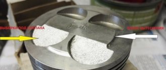
I encountered the following problem: I replaced the piston cap with an auto cap without valves. Diesel is no more. But on a hot engine, a hit appeared, which directly depends on the heating. The feeling is that the block comes off and the piston-cylinder air gap comes out (during installation I made 3 hundred parts). So, the point is that there are two methods of hardening that I found in the literature, 1st is a moment of 20 Nm (2 kgf m); 2nd - with a moment of 69.4-85.7 N m (7.1-8.7 kgf m); 3 ° - turn the bolts 90 °; 4 ° - finally tighten the bolts to 90 °. or Using a torque wrench, tighten the head bolts in three stages: first to 20 Nm (2 kgf m), then turn the bolts 90°, and then turn the bolts 90° again. he pulled out the first one. Is the question correct? If you have links to sources and please share.
Comments 51
In the official VAZ technological instructions for repairing engines TI 3100.25100.40157 on page 49 it is written that the bolts on engines 2112, 21124, 21126 and 11194 must be tightened in 4 stages: 1. Tightening torque 12... 20 Nm; 2. Tightening torque 26… 34 Nm; 3. Rotate 90 degrees; 4. Reverse rotation 90 degrees.
Here are the differences between the motors, taking into account the gasket, for metal in one, for parasite in the other, it remains to be seen which example is for what.
For these engines there is no difference regardless of the gasket. For engines of the “classic” family there is a difference: if a heat-shrinkable gasket is used, 2101 bolts and 2-stage tightening, if not shrinkage, 21213 bolts and 4-stage tightening. For 16 valve engines, only non-shrink seals are used and the tightening torque for them is the same - in 4 steps, as indicated in my comment.
so what's the difference? two books are different, there are still suspicions of a fake author, although how it is possible to put it into circulation with obviously incorrect information is possible, for example, for 8th grade and 16th grade, it’s generally a mystery.
What are these two books? I focus on the official VAZ technological education. The bolts for 8 and 16 valve engines are different: M12x1.25 - for 8 valve engines. M10x1.25 - for 16 valves. The length of the bolts is also different. The material may also be different. The load on the hinges also differs for 8 and 16 valves. As in classic engines, the bolts and their tightening torque depend on whether the gasket is used: shrink or non-shrink. Guides from various publishers, as well as tightening tips from local masters who say that they "feel with their hands that are stretched" (in fact, with your hands you can only feel a woman's ass or your own pussy and stuff like that) should be treated with caution, I wouldn't listen to the latter at all. In the “Dozen” and “Behind the Wheel” manuals, for example, I saw recommendations for tightening the cylinder head bolts in the form of 20 Nm + 90 degrees + 90 degrees, which is incorrect - such a connection will soon weaken.
I apologize for the stupid question, I’m not sharing a link to the company’s manual? The search request contains 10 pages of dubious sites, not a single link to an official source.
There is no reference, but the technical education itself is there. Write a letter in PM and I’ll send it.
What are these two books? I focus on the official VAZ technological education. The bolts for 8 and 16 valve engines are different: M12x1.25 - for 8 valve engines. M10x1.25 - for 16 valves. The length of the bolts is also different. The material may also be different. The load on the hinges also differs for 8 and 16 valves. As in classic engines, the bolts and their tightening torque depend on whether the gasket is used: shrink or non-shrink. Guides from various publishers, as well as tightening tips from local masters who say that they "feel with their hands that are stretched" (in fact, with your hands you can only feel a woman's ass or your own pussy and stuff like that) should be treated with caution, I wouldn't listen to the latter at all. In the “Dozen” and “Behind the Wheel” manuals, for example, I saw recommendations for tightening the cylinder head bolts in the form of 20 Nm + 90 degrees + 90 degrees, which is incorrect - such a connection will soon weaken.
How else is the 30-60-90 method and this is not an ideal life, these are moments in newtons)))
so how to pull it?
First way. First 2 kg: smoke. Then 7 kg (with this load the bolt begins to turn without increasing the force. And then 2 times by 90 degrees. With a break so that the gasket settles evenly.
Second question. I read a lot of literature on tightening bolts, if everything is clear with the tightening diagram, it is the same everywhere, so everyone writes about stresses differently. In the primer they write about 4 kg +90 +90, etc. In short, I use the following formula, M10 bolts are supposed to withstand a force of 10 kg, M12 bolts - 12 kg and so on, obviously unburned bolts. So I lift 4 kg first, then 6-7, then 8-9. I do all this with a break of 20, then 30 minutes... I don’t dare tighten the bolts to 10... Why don’t I use the pattern recommended in the primer? Because there it is suggested that after tightening with a force of 4 kg (in a sense), simply turn it 90 * a couple of times. If you follow this advice, it turns out that we will tighten the bolts with different forces, and our task is to tighten them with the same, uniform force... Good day everyone and Happy New Year.)))
Sometimes it happens that it is necessary to urgently replace the gasket or change the cylinder head. Such work at a gas station is not cheap, and to save money, you can try it yourself. This work is not difficult, but it requires attention; it is important to observe the sequence and tightening torque of the Priora 16 valve head.
Here you also need to know that the tightening sequence is different for 16cl and 8cl blocks, so you need to be careful. The torque on 16- and 8-valve engines is the same and is equal to four revolutions.
Video “How to properly tighten cylinder head bolts”
In this video, a master with extensive experience shows and describes in detail how cylinder head bolts are tightened correctly. On a Lada Priora car with a 16-cell unit, work is carried out according to the same scheme.
Today we took one of our old clients to Priora; as it turned out, the jammed pump broke the belt and, as a result, the valves were bent.
But progress at AvtoVAZ does not stop, and if on engines of the tenth family the valves simply fold, then even on the Priora 126 the connecting rods lose alignment and, if they are not changed, there is a high probability that the engine will start to eat oil, and therefore your money. Glory to the designers of AvtoVAZ!
But there are no breakdowns without good things; there are piston kits for 126 engines with grooves that do not bend the valve. In this article we will describe the procedure for repairing the cylinder head after a broken timing belt, as well as replacing the piston. Removing and installing the timing belt is described in this article, so we will not go into detail.
This procedure requires torque wrenches!
Diagram and tightening torque of the cylinder head in LADA Priora cars
Many owners of Lada Priora, in the process of car maintenance and repair, independently replace the head gasket or grind valves. When performing such work, it is important to observe the sequence and tightening torque of the cylinder head on the Priora.
In what cases is it necessary to tighten the block?
Tools and materials
Video “Installing and tightening the cylinder head on a Priora”
Comments and Reviews
Let's start to disassemble
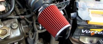
First drain the oil and antifreeze. We remove the protective cover, the air filter with hoses, and disconnect the connectors of the ignition coils, throttle cable and throttle assembly.
We remove the thermostat housing and at the same time disconnect all the connectors and hoses connecting them. We remove all the cables that were in our way towards the battery.
We remove the generator. We unscrew eight of the thirteen nuts holding the intake manifold and remove it. We unscrew all the bolts securing the valve cover, as well as the side engine support.
Unscrew the eight nuts and remove the exhaust manifold.
Remove the timing belt, camshaft pulleys and pump.
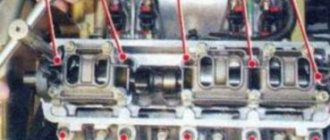
In three steps, so as not to deform the part, we first loosen and then unscrew twenty bolts of the camshaft bearing housing, head eight. Be sure to follow the sequence shown in the photo.
Remove the bearing housing. After removing the camshafts, there is a noticeable lip left on the intake camshaft.
Also, in several steps, we first loosen and then unscrew the ten head bolts. Be sure to follow the sequence shown in the photo.
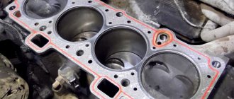
Remove the cylinder head. All sixteen valves have been replaced.
Photo gallery
The photo below shows the procedure for loosening the bolts and tightening them, which must be taken into account when repairing the cylinder head on a VAZ 2170 Priora.
Scheme for loosening bolts on an engine with 8 valves
Scheme for loosening bolts on an engine with 16 valves
16 valve head tightening diagram
8 valve head tightening diagram
Cylinder head repair
We mark all hydraulic lifters with numbers in the usual voicemail flourish and move them away. A regular magnet will help you pull them out. We dry the valves and remove the seals (valve seals), scrap valves, seals in the trash. Let's clear all channels. We take the head for polishing, just in case. Having once again rubbed it with kerosene and blown it with air, we begin collecting.
We arrange the newly acquired valves in the sequence in which they will remain in the cylinder head and, in turn, begin grinding in. Lubricate the valve stem with clean oil and apply lapping compound to the edge.
We insert the valve into its place and put a valve sharpening device on the valve stem. A manual grinding device is sold in stores, but since we are mechanizing the process in the twenty-first century. We take the old valve and cut out the stem from it, assemble a rubber tube of such a diameter that it can be worn with tension. One rod in the reversible drill, one end of the pipe on it, the other on the valve overlap. At low speeds we begin to grind the valve, constantly change the direction of rotation and periodically press it against the seat, then weaken the force. On average the valve takes twenty seconds to complete. We take it out and clean it. The valve is considered ground in if a uniform gray stripe with a width of at least 1.5 mm appears on the chamfer.
The same stripe should appear on the valve seat.
Video of manually grinding valves
For a sixteen-valve head, everything is the same, except there are twice as many valves. After lapping, thoroughly clean all valves and seats and rinse with kerosene to remove any remaining lapping paste. Let's check the tightness. We turn over the old spark plugs and put all the valves in place. We fill the kerosene and wait three minutes; if the kerosene does not flow, everything is fine, otherwise we grind off the valves on this cylinder.
I had to sharpen the four valves again, after which the kerosene stopped leaking.
Filled in new valve seals.
We put the valves in place and dry them. Before this, the valve stems are lubricated with clean oil. After lubricating it with clean oil, we put the hydraulic system pushers in place and, covering them with a clean rag, remove the head so that it is not visible. Finished the cylinder head.
crank mechanism
This main engine unit consists mainly of the following groups:
Each part of the group has several additional elements. For example, each piston carries a set of O-rings, a connecting pin and pin retaining clips. The crankshaft has bearings and oil seals. The most interesting thing is the structure of the connecting rods.
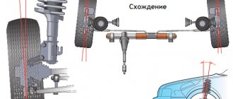
The principle of operation of the mechanism
VAZ engines, like other cars, are based on explosive combustion of fuel. The piston creates a certain compression of the air-gasoline mixture, a spark from the spark generator ignites it, pushing the piston down, and the crank mechanism (CPM) converts translational motion into rotational motion. This occurs due to the special shape of the crankshaft. The mounting points of the connecting rods are located so that while the connecting rods pushing the pistons rise, the connecting rods pushed by the piston are lowered. And this process takes place in shifts.
Set of connecting rods "Priors"
These parts are collapsible. The main part is made of high quality metal. Only in the upper ring, where the piston locking pin fits, is an insert made of a different metal installed. In general, the connecting rod consists of the following parts:
- connecting rod;
- liner covers;
- coupling bolts 2 pcs.;
- special washers;
- connecting rod bearing.
This is due to the fact that the liners have special grooves for the passage of engine oil. Due to the high rotation speed, this unit requires uniform and abundant lubrication. The slightest discrepancy between these grooves and the oil supply holes of the crankshaft will lead to a disruption in the flow of lubricant and, as a result, jamming of the engine.
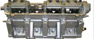
Let's move on to the cylinder block
We remove the pallet. Rotating the crankshaft as convenient for us, unscrew two bolts on each connecting rod cap. For this we use a TORX E10 head.
We take out the piston along with the connecting rods. To do this, use the wooden handle of a hammer to rest against the connecting rod from below and lift it slightly. We remove the old inserts and buy new ones of the same size according to the markings on them. Here is another stone in AvtoVAZ’s garden; the owner’s car was never lifted from the cab to the engine, but three pistons were from group “B” and one “C”. It turns out that at the factory the cylinder was sharpened a little and simply stuck into an enlarged piston, no words. There are no options, let's take group “C”, don’t sharpen the engine for this. We will not touch the root inserts.
We purchase a new piston assembly that does not bend the valves, connecting rods and connecting rod bushings.
Eliminating longitudinal play of the crankshaft
It was visible on this engine. To eliminate it, replace the thrust half-rings. Standard and repair sizes available. We take the first repair measures; if they are tight, we sharpen them a little. We unscrew the central main bearing and carefully press the half rings with a screwdriver. The sign on it is in the shape of the three graces shown below.
When the half ring has come out a little, we turn the crankshaft, it will push it out. Half rings of two types are white at the front and yellow at the rear; the grooves on them should point towards the cheeks of the crankshaft.
While we are installing and removing the new half rings, if they fit in with great effort, you can sand them a little on a fine abrasive bar, but not from the side of the grooves. Let's check the rollback. We tighten the main bearing with a torque of 8 kgf * m.
Assembling the piston
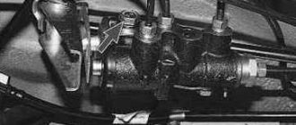
An arrow is thrown out above the piston, it should be directed towards the front of the engine. And there are marks on the connecting rod, which in turn should look the same. Don't mix!
Insert the retaining ring into the groove on the piston. We insert the connecting rod into the piston and, having lubricated ours and the piston pin with oil, insert it into place. Insert the second retaining ring. This operation, even if it seems simple, will have to suffer. We inspect the assembled structure; all retaining rings must be clearly in their grooves, otherwise, with the engine running, a protruding ring can cause a lot of trouble.
After assembly, it is necessary to break the connecting rod bearing cap, since the connecting rod is made of one piece. This is the case with our cars. First, unscrew the bolts. We insert the connecting rod into the cleats at the level of the mark shown in the figure with a black arrow, and squeeze it slightly, then break it with a slight movement of the hand. Very scary the first time. We put the cover in place and tighten the bolts so as not to mix it up in the future.
Checking the thermal gap in the piston rings
We place each set of rings on each cylinder. In the future we do not change their places. We insert each ring in turn into our cylinder and lightly push it with the piston approximately in the center.
We measure the gap with feeler gauges.
Nominal clearance: 0.25 - 0.45 mm.
The maximum distance for all is 1 mm. But it already tastes boring.
Installing new rings
First we install the expansion spring of the scraper ring, then the ring itself. The scraper ring holder should face the opposite side of the spring holder. We then install the lower compression ring and finally the upper compression ring. The rings must have the inscription “TOP” embossed on them, it should look up. The rings in the piston grooves must rotate easily.
Features of tightening fasteners
Even a non-professional can handle this work. It is important to follow two rules - the tightening torque and the sequence of working with fasteners. The tightening torque on engines with 8 and 16 valves is no different, while the sequence is different. Pay attention to the diagrams below; numbers indicate the order of tightening the bolts.
It is necessary to pay attention to the cylinder block:
- if during operation the bolts become loose due to vibration (the malfunction is detected by leakage of the gasket);
- after dismantling the cylinder head and installation;
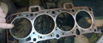
- if the iron gasket is replaced;
- during tuning of the cylinder block.
Before work, take the instructions from your Priora to understand which engine is installed in the car.
Engine assembly
We wipe the crankshaft pins, cylinder mirror and connecting rod bearing seats with a clean rag; by the way, you can degrease them. We insert new liners into the connecting rod and cover so that the antennae of the liners fit into the grooves.
Lubricate the liners, crankshaft pins and cylinders with clean oil. We open the elastic bands in blocks as shown in the figure, the angle between them should be 120 degrees.
We put a mandrel on the piston to compress the rings, having previously lubricated it from the inside with clean oil. Not forgetting the direction, the arrow on the piston should be directed towards the front of the engine, insert it into our cylinder.
Turn the crankshaft so that the connecting rod is at the bottom. Lightly tap the wooden handle of the hammer to press the piston into the cylinder. Remove the spindle and push the piston until the connecting rod rests on the crankshaft. Place the connecting rod bearing cap on the bottom, remembering the marks. Tighten the connecting rod cover bolts to a torque of 5 kgf * m. We repeat the same with all other cylinders.
We put back everything that was removed from below. We blow air from above and clean the holes for the head bolts. We install a new head gasket and the head itself. Lubricate the bolts with a thin layer of oil, most importantly without fanaticism. We tighten the bolts in several stages in the reverse order of unscrewing, see the photo at the beginning of the article. The tightening sequence is as follows:
- first we tighten everything with a torque of 2 kgf * m
- then tighten everything with a torque of 7-8 kgf * m
- rotate 90 degrees
- rotate 90 degrees again
We install hydraulic lifters, camshafts and camshaft bearing cover. All rubbing surfaces are lubricated with clean oil. Before installing the camshaft bearing cap, lubricate the perimeter and rims around the spark plug wells with a thin layer of sealant. Tighten the bearing cover bolts in the reverse order of unwinding, with a torque of 2 kgf * m, see photo at the beginning. Well, let's install all the parts in the reverse order of removal. Fill in all the fluids and let's get started, it may not start right away, this is normal. At the first start it will smoke well until the oil on the cylinders runs out, we see that the oil pressure light goes out. Let it work for a minute and turn it off, suddenly we look where something has flowed. We turn it on several times, constantly increasing the operating range, bringing it to operating temperature, constantly checking the oil and antifreeze, and also pay attention to ensure that there are no extraneous noises. Let it rest for an hour and then idle again for about an hour, constantly monitoring the temperature. Well, if the break-in is abrupt, if not, you can only drive the first thousand kilometers, try not to increase the speed beyond 3000 and not tow.
Nuances of work
At different times, Lada Priora cars were equipped with engines with a displacement of 1.6 and 1.8 liters and a different number of valves in the heads - V8 (or 8V) and V16 (or 16V). The type of unit head determines the size of the bolts, the order of their installation and the tightening torque of the cylinder head on the Priora.
If the car has an 8-valve engine, then it can use head mounting bolts of different sizes:
- on old motors 21114, M12*1.25 hex head screws are used;
- on more modern 21116, which went into production approximately in mid-2011, M10*1.25 elements with an asterisk head are installed.
When installing a removed head, it is necessary to use new screws, since the old ones will be stretched and have internal damage.
Also, the engines use gaskets of different designs - combined on the old unit and all-iron on the new one. The procedure for tightening bolts for engines with metal and combined gaskets is absolutely identical.
The main nuances when performing work are checking the length of the fasteners, observing the sequence of tightening the screws and monitoring the tightening force. Violation of these conditions leads to damage to parts and the need for additional repair work. The procedure itself is not complicated and can be done independently in any convenient place - in a garage or in an open parking lot, with the exception of the case of installing the head on the engine, which is preferably installed indoors.
It is important to remember that tightening the bolts “by eye” without a torque wrench is unacceptable, since a uniform fit of the mating surfaces of the head and block will not be ensured.
Tools and materials
Before starting the tightening procedure, you should prepare everything necessary to perform:
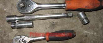
- wrench with built-in dynamometer up to 100 H⋅m;
- a set of sockets and regular keys;
- Togh E14 key;
- calipers for measuring the remaining length of bolts;
- plate with a marked scale up to 180 degrees;
- new bolts.
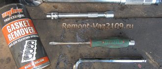
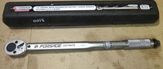
A torque wrench is an important tool for DIY repairs.
Step-by-step instruction
Sequence of operation on an 8 valve engine:
- Wipe the cylinder head surfaces and dry the bolt holes in the engine block.
- Install the gasket on the block and align it along the guides.
- Mount the head on top and insert 10 M10 or M12 mounting bolts. If the owner decides to save money and keep the old screws, then they should have a length of no more than 135.5 mm.
- Tighten the elements according to the diagram. The tightening force should not exceed 20 N⋅m.
- Then you need to re-tighten the bolts. The second tightening force should be in the range from 70 to 85 N⋅m.
- Next, you need to tighten the screws by 90 degrees in the same sequence. The rotation angle can be controlled using a special device, which is a plate with an attached scale from 0 to 180 degrees.
- In accordance with the regulations, you need to tighten the bolts again by 90 degrees.
- The attachment of the 8 valve head to the block is complete.
- After assembling the motor, you need to check the quality of operation by starting and warming up the engine. A securely tightened joint between the head and the block should not allow working fluids to leak from the crankcase of the power unit.
Malfunctions: causes, elimination
Like all internal combustion engines with mechanical adjustment of valve clearances, the 11186 engine requires periodic adjustment of this characteristic. In addition, during operation, characteristic “diseases” of this particular version of the power drive were identified:
| Timing belt | 3/50 |
| battery | 1/20 |
| Valve clearances | 2/20 |
| Crankcase ventilation | 2/20 |
| Belts that drive attachments | 2/20 |
| Fuel line and tank cap | 2/40 |
| Motor oil | 1/10 |
| Oil filter) | 1/10 |
| Air filter) | 1 – 2/40 |
| Fuel filter) | 4/40 |
| Heating/Cooling Fittings and Hoses | 2/40 |
| coolant | 2/40 |
| Oxygen sensor | 100 |
| Spark plug | 1 – 2/20 |
| Exhaust manifold | 1 |
| Bend valves | broken timing belt | periodic wear monitoring |
| Ignition system interruptions | failure of the corresponding block | replacing the ignition module |
| Increased oil consumption | development of main liners |
When repairing piston and crankshaft engines, it is recommended to use original components from the AvtoVAZ manufacturer. Because only he uses special technologies for strengthening structural materials. From third-party companies, the metal may be “raw”; the resource of such consumables cannot be analyzed.
How to tighten main bearings and connecting rod bearings
So, taking into account the above, it becomes clear that the tightening torque of the main and connecting rod bearings is extremely important. Now let's move on to the assembly process itself.
- First of all, molar liners are installed in the bed of the molar necks. Please note that the middle liner is different from the others. Before installing the bearings, the preservative lubricant is removed, after which a little motor oil is applied to the surface. After this, the bed covers are placed, after which the tightening is carried out. The tightening torque should be that recommended for the specific model of the power unit. For example, for engines on the VAZ 2108 model, this figure can be from 68 to 84 Nm.
- Next, the connecting rod bearings are installed. During assembly, it is necessary to accurately install the covers in place. The specified covers are marked, that is, their arbitrary installation is not allowed. The tightening torque of the connecting rod bearings is slightly less compared to the main bearings (the indicator ranges from 43 to 53 Nm). For Lada Priora, the main bearings are tightened with a torque of 68.31-84.38, and the connecting rod bearings have a tightening torque of 43.3-53.5.
Errors when installing the head
If you do not use a torque wrench when installing the cylinder head, you may make a mistake with the force, which will lead to uneven torque. In such cases, there will be excessive or insufficient force, which will result in either deformation of the head surface or allow the breakthrough of gases, oil or coolant. In both cases, this is fraught with serious consequences for the engine.
If you follow the rules for tightening the fastening bolts, as well as the required torque, you can always count on reliable and durable operation of the installed parts. The gas distribution mechanism in the engine plays a major role, so you should not neglect the rules for installing the component elements.