The location of the relays and fuses, as well as the differences in the mounting blocks, is here www.drive2.ru/b/538898/
Scheme of VAZ-2108, 2109 with a low instrument panel (early versions)
content-5.foto.my.mail.ru…hofer2107/1348/s-3867.jpg There is a “parking light” function - turning on the left or right lights in the parking lot.
Scheme of VAZ-2108, 2109, 21099 with a low panel (later versions)
content-21.foto.my.mail.r…hofer2107/1348/s-3815.jpg There is no brake pad wear sensor (previously, the handbrake lamp blinked when the lever was raised, and came on constantly when the sensors on the brake pads were activated).
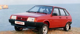
Years of production 2108: 1984—2003 in Russia, 2003—2014 in Ukraine
Scheme of VAZ-2108, 2109, 21099 with a high panel and Euro fuse block 2114
content-21.foto.my.mail.r…hofer2107/1348/s-3812.jpg Fog lights, central locking, heated seats and electric windows.
Years of production 2109: 1987-2004 - in Russia, 2004-2011 - in Ukraine
Connection diagram for headlight cleaners on low and high panels of cars produced after 1989
content.foto.my.mail.ru/m…hofer2107/1348/h-3928.jpg The headlight cleaners are turned on with a button, in place of the relay there is a jumper.
Years of production 21099: 1990-2004 - in Russia, 2004-2011 - in Ukraine
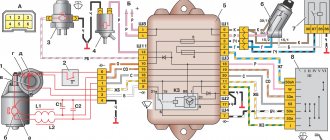
Diagram of a mixture control system with a controller under the hood
content-10.foto.my.mail.r…hofer2107/1348/s-3906.jpg
Diagram for switching on fog lights since 2000 on a high panel
Since 2000, in accordance with UNECE rule 48-01, the electrical circuit for switching on the rear fog lights has been changed on parts of VAZ vehicles. Added rear fog light relay 2114-3747610, and rear fog light switch 21093-3710030-10 (like a regular one, only without fixing). Instrument panel harness used 21099-3724030
We are reworking the activation of the rear fog lights according to the latest scheme. That is, the button will not be fixed: if the headlights or front fog lights are on, press and release the button for the rear fog lights - they turn on. They turn off when you press the button again or automatically when you turn off the headlights. That is, we will never forget to turn them off. For high panel. You need rear fog lamp relay 2114-3747610. It may look different, it is also used on the VAZ-2114, 2110, GAZ-3110... It is advisable to find a connector for it, you can just wrap the usual terminals with electrical tape and stick it in.
Comments 10
I can’t find this, where the green one comes in and where it goes
The green one goes to the size button, light switch, can go to the fuse for the rear fog light button (it is located right next to the button) or can connect to the 3/8 mounting block. In this case, power went to the headlight cleaner fuse and from it to sh3/21 from which power went to the button. That is, in the second option, the fuse in the mounting block is responsible for the headlight wipers (if any) and for the rear fog lights and there is no fuse next to the button. In the second option, there is not a green wire going to the button, but an orange-white one. In the photo ad-cd.net/169d0das-480.jpg the top two pictures are options for connecting the button. So there may not be any green. We check the power on the green or orange-white wire of the button when the ignition and headlights are turned on.
I have an old-style mounting block, can it affect anything?
If you put the wiring under a new type of mounting block, it will not work. Does the button have a green or orange/white wire?
Hi, I had a 21099 96 with a low panel before they changed it to a high one, I can’t do the rear PTF, there are no these wires, what should I do?
I advise you to start by looking for the connector for the button next to the stove control levers where it was on the low panel, maybe it is still there. Then you need to extend it and connect the indicator light next to it (to the black and orange-black).
If there is no connector, then here is a diagram for connecting the rear PTF ad-cd.net/6584a32s-960.jpg Take the button. Contacts 7 to black and 6 to white to the same wires of the glass heating button (backlight), contact 10 through a 10 Amp fuse to the green side button, and contact 9 to the indication light (its second contact is to the black contact 7 of the button, this is a minus) and to orange -black wire for wiring to the rear lights. The wiring runs to the left of the clutch pedal from the mounting block to the floor. You need to find the orange-black wire there, cut it and connect it to the button, or you can press the lock of its terminal and pull it out of plug 9 of the mounting block.
Thank you for such a complete and clear answer)) we will try
I advise you to start by looking for the connector for the button next to the stove control levers where it was on the low panel, maybe it is still there. Then you need to extend it and connect the indicator light next to it (to the black and orange-black).
If there is no connector, then here is a diagram for connecting the rear PTF ad-cd.net/6584a32s-960.jpg Take the button. Contacts 7 to black and 6 to white to the same wires of the glass heating button (backlight), contact 10 through a 10 Amp fuse to the green side button, and contact 9 to the indication light (its second contact is to the black contact 7 of the button, this is a minus) and to orange -black wire for wiring to the rear lights. The wiring runs to the left of the clutch pedal from the mounting block to the floor. You need to find the orange-black wire there, cut it and connect it to the button, or you can press the lock of its terminal and pull it out of plug 9 of the mounting block.
What kind of problems does an electrical circuit help to solve?
The electrical circuit for the VAZ-2109 injector is, of course, several times more complicated than for carburetor cars. However, this is not at all surprising, because models with distributed fuel injection have numerous electronic devices built into them, which, unfortunately, can fail. An interactive diagram helps solve many problems:
- provides the driver with information about the functionality of all electronic devices;
- transmits a control pulse to electronic elements;
- acts as electrical protection for all electronic devices;
- protects the system from short circuits.
Useful tips
The VAZ 2109 wiring diagram is necessary without any intention of making changes to the car’s structure, because during operation the wiring is subject to:
- Temperature effects - both climate changes and daily heating and cooling cycles;
- Mechanical loads - wiring runs throughout the entire car body, exposed to components and mechanisms, passengers and transported goods
Accordingly, the owner is required to perform a preventive inspection of the standard wiring in order to identify insulation violations and mechanical damage. Timely detection of a malfunction will allow you to quickly correct and prevent more significant failures in the operation of the vehicle’s electronic devices.
Conclusions: we hope that the issues covered in this article will protect you from thoughtless intervention in the electrical circuit of your car. And if you need to replace the standard wiring, you will do it in accordance with the manufacturer’s recommendations.
Types of electrical circuits
There are several options for circuits for monitoring the condition of electrical equipment of the VAZ-2109:
- With a "high panel". This scheme is considered as the most interactive and relevant. It provides an additional circuit that is intended for an automotive mounting block.
- With a "low panel". This circuit is used to identify a malfunction in the automotive mounting block.
- With Europanel. This version of the diagrams provides complete information for both the internal diagram and the mounting block. It also includes a diagram that helps to connect a Europanel, that is, electrical devices and appliances created according to the “Euro” type.
What's inside the cabin
Replacing the power unit will also require replacing the interior wiring.
Many owners combine this process with replacing the instrument panel with a modern one:
- the “high” panel from the VAZ 21099 fits without modification;
- The “LUX” panel from the VAZ 2114 model is suitable with minor modifications.
Tip: there are a lot of videos on the Internet that describe in detail the process of finalizing the panel. Read them all carefully before starting work on your car.
How the signal is transmitted
From the electronic unit, a signal is transmitted through special wires, which are painted in different colors, to the system that controls the functionality of the engine.
Thanks to the different color markings of the wires, the driver can understand the electrical circuit and find exactly the wire that is needed to solve a particular problem. To ensure high-quality and uninterrupted transmission of the electrical signal, you must do the following:
- use wires with a suitable cross-section;
- monitor the contact resistance, which should be minimal for removable connections;
- monitor the integrity of the insulation of electrical conductors.
The operation of the VAZ-2109 injector engine, as well as its dynamic characteristics, is primarily affected by the condition of the electrical wiring, therefore, it must be constantly and carefully monitored.
Having familiarized yourself with the intelligent color wiring diagram, even without the presence of a special measuring device, you can quite easily independently find a fault in the electrical wiring, even the most insignificant one. Eg:
- find out why the ignition stopped working;
- determine why the starter does not turn on;
- due to which the generator lacks voltage;
- which led to a breakdown of the heating system.
If the cross-section of the conductor decreases, this will lead to a deterioration in the transmitted electrical signal, which will subsequently increase the temperature. Sometimes an external examination will not help to identify a violation of the integrity of the veins, and only a deep examination will help to identify such destruction. The integrity of the wiring is compromised due to oxidation of the contacts, and since such a process is inevitable when operating machines, this means that they need to be cleaned periodically.
If the electrical signal is supplied in a distorted form, then the malfunction will be felt throughout the entire VAZ-2109 injector system.
Engine compartment modifications
In addition to replacing the power unit after it has exhausted its life, there are many components in the engine compartment whose wiring also needs to be replaced:
- high-voltage wires from the ignition unit;
- wiring of various control sensors;
- battery power cables (connections are most susceptible to corrosion).
Numerous sensors in the engine compartment require special monitoring:
- Coolant temperature sensor - if the electrical wiring is faulty, the driver will not notice overheating of the power unit;
- Brake fluid level sensor in the expansion tank - a leak or low level can lead to brake system failure;
- ABC system sensors - oxidation of contacts or disruption of wiring integrity can lead to system failure;
- Exhaust gas sensor - based on its readings, the electronic unit “prepares” the fuel-air mixture. If the sensor does not work, gasoline consumption will increase.
A useful addition to the functionality of the car is the acquisition of a modern anti-theft system.
Installing a modern alarm system is a special topic, since its work affects several main components and systems of a VAZ family car:
- General electrical system;
- Supply system;
- Sound and light circuit and actuators (side lights, headlights, sound signals);
- Standard immobilizer.
Advice: often manufacturers of alarm systems accompany the installation process with video and photo materials for each specific model of a particular family of cars. Before starting installation, you should read them carefully.
General alterations
Installing additional fog lights is a general modification because:
- Affects equipment in the engine compartment;
- Interferes with the instrument panel inside the cabin;
- Connects to the vehicle's standard power supply system;
- Attached to the power body.
To install and connect fog lights, you will need a wiring diagram for the VAZ 2109, because the package includes:
- Connecting wires;
- Terminal blocks;
- Switching relay;
- Actuators (buttons);
- A backlight lamp (or LED) indicating the status of lighting fixtures.
Additional tips from the professionals
By taking into account some tips and tricks provided by professionals, you can independently extend the life of your car wiring:
- car owners must periodically inspect the external condition of the insulation and all connectors by looking under the hood of their car;
- If a minor defect is discovered during inspection, the damaged wire must be replaced to prevent a short circuit. If the break is insignificant, then you can wrap it with high-quality electrical tape for a while, but it is not recommended to postpone replacement for a long time;
- A special product, WD-40, which can be purchased at an affordable price in a specialized store, will help remove the oxidizing layer from the surface of the connector;
- It is advisable to make additional protection for the engine crankcase to prevent moisture from getting on the wires.
It is imperative to wipe off excess oil from the insulation to extend its service life. Experts strongly recommend replacing old or damaged wiring rather than repairing it, in order to avoid more serious breakdowns in the future, which will cost car owners several times more.
Schematic electrical diagrams, connecting devices and pinouts of connectors
The VAZ-2109 car was produced at AvtoVAZ from 1987 to 1997. Years of production 21099: 1990-2004 - in Russia, 2004-2011 - in Ukraine. Here are colored wiring diagrams (for the injector and carburetor) with a description of all the elements for various modifications. The information is intended for self-repair of cars. Electrical circuits are divided into several blocks for ease of viewing via a computer or smartphone; there are also circuits in the form of a single picture with a description of the elements - for printing on a printer.
Search algorithm
You need to start with something simple - determine whether an electrical impulse is supplied to the spark plugs:
- Remove the tip from the first candle;
- We expose his contact;
- We bring it to the metal part (possibly to the cylinder block) at a distance of 4-5 mm;
- We run the starter for a couple of seconds;
- Let's see if there is a spark.
Advice: in this way we divide the troubleshooting. If a spark is supplied to the spark plugs, then it is unlikely that all 4 have failed. This means that the problem of failure should be sought in the power system.
If there is no spark, then we continue to search for a malfunction in the ignition system.
To do this, we carry out a spark test:
- We remove the central wire coming from the coil from the distributor cover (ignition distributor);
- We bring it again to the metal part of the engine;
- We turn on the starter and watch to see if an electric discharge passes through.
Advice: If there is no spark, then further troubleshooting should be carried out using diagnostic tools. Moreover, every owner who independently maintains the car should have such devices. Moreover, their price is low.
The simplest but effective devices have long been produced for motorists. With their help, you can diagnose a fairly large contingent of cars from the domestic automobile industry:
- A family of VAZ cars (models 2108, 2109, 2110) that have the same connectors for electronic switches;
- Cars of Ukrainian origin (Tavria and ZAZ);
- OKA cars, etc.
Of course, with their help it is impossible to determine whether the VAZ 2109 engine compartment wiring needs to be replaced, but they are able to detect a failed electronic unit or electrical circuit. Their functions include:
- Checking the functionality of the ignition coil;
- Checking the Hall sensor;
- Checking the operation of the ignition switch and contact group;
- Checking the ignition relay.
It is enough to connect the MD-1 device instead of the standard switch and turn on the ignition (without starting the engine). With the help of LED lamps built into the housing we will see:
- The ignition relay and lock are operational if the “P” LED lights up;
- The primary winding is in working condition if the “K” LED lights up;
- We turn on the starter for 1-2 seconds and monitor the LED “D” - if it starts blinking, then the Hall sensor is operational.
Conclusions: knowledge of the operating features of the VAZ-2109 car systems, and the simplest diagnostic instruments will help you quickly find the failure problem and also quickly eliminate it.
voice
Article rating
Modifications of VAZ-2109
VAZ-2109 . The basic model, which was produced from 1987 to 1997, was equipped with a 1.3-liter VAZ-2108 carburetor engine with a capacity of 64 horsepower.
VAZ-21091 . Modification of a car with a derated VAZ-21081 engine, 1.1 liter and 54 horsepower. It was mass-produced from 1987 to 1997.
VAZ-21093 . Modification of a car with a VAZ-21083 carburetor engine, 1.5 liters and 73.4 horsepower. Serially produced from 1988 to 2006.
VAZ-21093i . Modification with a VAZ-2111-80 injection engine, 1.5 liters. the first prototype appeared in 1994, mass production began in November 1998.
VAZ 21093-22 . Model made specifically for the Finnish market. It features improved interior trim, pre-installed alloy wheels and a new dashboard. The car was equipped with a 1.5 liter injection engine. Produced from 1995 to 1998.
VAZ-210934 . An all-wheel drive SUV with a VAZ-21093 body mounted on a Niva frame, on which the suspension, steering, engine, gearbox and transfer case from the same VAZ-2121 Niva model were already installed.
VAZ 2109-90 . A variant of the car, which was equipped with a compact two-section Wankel rotary piston engine with a volume of 654 cm3.
VAZ-21096 . Export modification of the VAZ-2109 for countries with left-hand traffic, the steering column was located on the right.
VAZ 21097 . Export modification of VAZ 21091 with right-hand drive.
VAZ 21098 . Another export modification, but this time the VAZ 21093 model with a right-hand steering column.
VAZ-2109 Carlota . A car produced from 1991 to 1996 in Belgium by Scaldia-Volga.
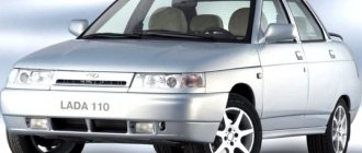
VAZ-21099 . The next independent car model, which is a modification of the “nine”. This car had a 4-door, 5-seater sedan body and a rear overhang extended by 200 mm.
Basic tips for working with automotive electronics
Let’s immediately agree that installation, removal and any other work with car wiring are the most complex operations, which are taught in secondary specialized educational institutions. This article is for informational purposes only on working with the electronics of VAZ models and contains solely a description of the basic aspects of these procedures, so it will not be possible to learn from it all the intricacies of wiring repairs. Familiarization with these lies only through long and hard work associated with work practice in the field of automobile repair.
Returning to the main topic of today’s material, it would not be out of place to note: even a person without special skills in this path has the opportunity to install the wiring of any car with his own hands. However, for proper implementation of all procedures it is extremely important:
If everything is extremely simple with points 1 and 3 of this list, then aspect 2 of the repair work is worth understanding. For our readers, we present a basic list of all those tips, the observance of which is extremely important for proper work with car electronics, in particular with the wiring of VAZ models:
We assure you that by adhering to the tips described above, any work with car wiring will be marked for the motorist with success and, most importantly, the safety of all repair operations.
Wiring diagram for VAZ-2109 carburetor
- Headlight.
- Electric motor for headlight glass cleaning system. An optional part, used mainly on export vehicles.
- Limit switch for powering the engine compartment lamp.
- Klaxon.
- An electric motor drives a fan installed on the radiator of the cooling system.
- Temperature indicator that provides a control signal for the electric drive of the fan impeller.
- Alternator.
- Fluid supply valve for headlight glasses. Used in conjunction with paragraph 2.
- Fluid supply valve for the glass of the fifth door.
- Fluid supply valve to the front glass.
- Spark plugs.
- Hall sensor used to distribute ignition pulses.
- Coil.
- Limit switch for reverse gear lights.
- Fluid temperature meter in the cooling system.
- Starter.
- Accumulator battery.
- A sensor that measures the fluid level in the brake booster.
- Switch that controls the ignition system.
- Sensor for determining the position of the top dead center of the piston of the first cylinder. Installed on some export VAZ 2109 with a diagnostic system. Found only on cars before 1995.
- Diagnostic block. Optional element, installed together with item 20.
- Controller for controlling the solenoid valve installed in the carburetor.
- Starter switch contact block.
- Limit switch on the carburetor.
- Economizer valve.
- Sensor signaling an emergency decrease in oil pressure.
- Washer pump drive.
- Fan impeller motor for ventilation and heating systems.
- Resistance providing additional fan speeds.
- Speed shifter.
- Windshield wiper drive.
- Cigarette lighter.
- Illumination system for levers for adjusting heater operating parameters.
- Socket for additional equipment.
- Lamp for auxiliary lighting of the engine compartment.
- Illumination system for the glove box on the instrument panel.
- Relay and fuse link mounting block.
- Instrument panel light switch.
- Parking brake lamp limit switch.
- Brake lamp limit switch.
- Steering column switch lever block.
- Exterior lamp switch.
- Hazard switch.
- Turn on the rear fog lamp.
- Bimetallic fog lamp fuse.
- Heated glass switch on the fifth door.
- Turn signal repeaters on the front fenders.
- Central interior lighting.
- Individual lampshade.
- Switches for backlight operation on the middle pillars.
- Ignition switching unit.
- Egnition lock.
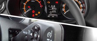
- “Low” type instrument cluster.
- Choke limit switch on the carburetor.
- Rear lights.
- Fuel level meter in the tank.
- Heated glass.
- Rear wiper drive.
- Two lamps for room illumination.
Wiring diagram VAZ-2109 carburetor - full view:
All carburetor “nines” use the same non-contact ignition system, built on the basis of an electronic switch and a Hall sensor.
The failure of the electronics control unit, which is typical for the Nine, occurs due to the fact that the housing allows water, dust and moisture in the form of condensation to pass through. The factory provided a tiny groove to drain water from the housing, but it constantly gets clogged, the housing fills with water, and the control unit slowly fails.
Main reasons for refusal
If the engine does not want to start, but the starter rotates the crankshaft, then the main reasons are known:
- Either the air-fuel mixture is not supplied to the cylinders;
- Either there is no one to “ignite” this very mixture - there is no spark.
Supply system
Checking whether fuel is getting into the cylinders is quite simple. For this:
- We take a spark plug wrench from the standard tool kit;
- Remove the high-voltage wire from the spark plug of the first cylinder;
- We unscrew the spark plug with our own hands;
- We look at it carefully.
Tip: if the spark plug is wet and smells of gasoline, it means the air-fuel mixture is entering the cylinders. You should look for the reason for the refusal. If not, then you need to look for the cause in the power system components. Videos about eliminating such failures are available on the Internet.
Ignition system
The first step in troubleshooting should be to start by testing the ignition system, since quite a lot of devices take part in the sparking process:
- Spark plug;
- High voltage wires;
- Ignition distributor (on carburetor engines);
- Hall Sensor;
- Switch;
- Ignition coil.
Equipment diagram for VAZ-2109 injector
The VAZ 2109 wiring for the injector has many connectors for connecting sensors to the computer.
- TPS (throttle position sensor);
- DPKV (crankshaft position sensor);
- DT (temperature sensor);
- DSA (vehicle speed sensor);
- Canister purge valve;
- MAF (mass air flow sensor);
- DD (knock sensor) and others.
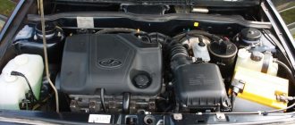
The weak point of the harnesses is the power wiring on the bottom shelf of the radiator, which is constantly exposed to high temperatures and in this place it is in no way protected from water and dirt. Another problem is a harness under the carpet next to the driver's seat. Moisture constantly accumulates there, and in order to remove it, you need to dry the floor, inevitably tugging on the rope.
Since the mid-90s, VAZ 2109 began to use engines with an injection system, which greatly changed the electrical layout of the engine compartment and instrument panel. Below is an electrical diagram of a 1999 car with an ECM type GM ISFI-2S and January 4/4.1.
How the injector wiring should work, how to connect it yourself
When deciding to make major modifications to their car, or restoring it after serious breakdowns, many motorists are faced with the need to replace the wiring. In the design of any car, it is possible to replace either the under-hood wires, mainly coming from the injector, or the interior electronics that ensure the operation of application devices. In today’s article we will look at the features of repairing and replacing both types of wiring, taking VAZ cars as an example. Interesting? Then be sure to read the article below to the end.
Relay and fuse box diagram 2109
The fuse blocks do not depend on the fuel injection system used - carburetor or injector. BP will differ only by year of manufacture of the car. That is, the mounting blocks for the carburetor and injector are the same. The VAZ 2109-099 fuse box (carburetor, injector) is located under the hood, in the compartment in front of the windshield on the left side.
Fuse block 2114-3722010-18
K1-relay for turning on headlight cleaners; K2-relay-breaker for direction indicators and hazard warning lights; K3 - windshield wiper relay; K4-relay for monitoring the health of lamps; K5-power window relay; K6 - relay for turning on sound signals; K7-relay for turning on the electric heating of the rear window; K8-relay for high beam headlights; K9-relay for low beam headlights; F1-F16 - fuses.
Fuse block 2114-3722010-60
K1 - Headlight wiper relay, K2 - Turn signal and hazard warning relay, K3 - Windshield wiper relay, K4 - Brake light and parking light relay, K5 - Power window relay, K6 - Horn relay , K7 - Rear window heating relay, K8 - Headlight high beam relay, K9 - Headlight low beam relay, F1 - F16 - Fuses, F1 - F20 - Spare fuses.
Attention! The power terminals on the generator often become loose, heat up, spark and melt the wiring. Pay attention to this point when searching for possible faults yourself.
A few words about the procedure for working with wiring
At the end of today’s article, we’ll look at exactly how you should proceed if you want to change the wiring. As an example, let's take standard models of the VAZ brand - 2110, 2109 and the like. So, to competently work with car data electronics you will need:
Of course, the noted procedure is only generalized, but, in general, compliance with it and compliance with the described rules for working with car wiring is the key to the success of such repairs. We hope that today's material was useful to you and provided answers to your questions. Good luck in maintaining and operating your car!
Source
Weak spots
What weak points does the body of the domestic nine have? Let's try to find out.
If rotten or deformed elements of the car body are detected, they must be removed and appropriate measures taken to restore the integrity of these areas.
The most vulnerable areas of the VAZ 2109 body include:
- Front floor, reinforced sills, doors, fenders and rear underbody;
- The hood has relative endurance, but over time it begins to lose its former properties. The area above the battery is especially affected. This is where Nine owners most often notice the formation of rust;
- A noticeable problem that many drivers face is the fuel tank floor;
- Optics reflectors and a muffler also cannot boast of a long life without the appearance of signs of rust.
Corrosion is obvious
Corrosion is the main enemy of almost all domestic cars. Although anti-corrosion coatings are done quite well, time, weather conditions and the characteristics of our roads kill everything, rust actively begins to eat the metal and this problem must be dealt with.
Dealing with problems in general terms
To get rid of the problem of rust formation on the body, you need to do some work. On your own or with the help of specialists, decide for yourself.
- Disassemble the engine compartment, drain the coolant and remove the radiator.
- Remove all doors.
- If there is an amplifier (TV) in front, then it will also have to be disassembled.
- Using a grinder, all damaged areas are cut off;
- If the wings or panels are rusty, they will have to be cut off.
- If holes or holes have formed due to corrosion, they can be welded or patches can be used.
- It is recommended to additionally cover areas that are not highly resistant to corrosion with metal inserts.
- Experts advise strengthening mudguards with additional inserts and then securing them with spot welding.
- New body parts that are installed in place of rusted ones must be adjusted in accordance with the standards.
- After processing, the wings and sills are secured with screws, bolts and welding.
- Restoring the geometry of the body is a mandatory activity, on which most of the time is spent. To do this, you will need a bench machine on which the machine is fixed and adjusted in accordance with the norms of the control points.
- The next stage is welding a new floor, if required as a result of assessing the condition of the body. When restoring the floor, patches, connectors and amplifiers are used. At the final stage, the floor is covered with anti-corrosion compounds.
- It is easier to purchase new arches than to try to restore old ones. They can be coated with resin and waste oil mixed together. This mixture is excellent at resisting rust. Just do not use this composition to treat the bottom under any circumstances.
During body repairs, it is often necessary to jack up the car. If the jacking areas are rusty, use a support beam to lift the car.
Holes, rust
Often, the body is repaired independently if small areas are damaged, dents or holes are formed due to the effects of rust. In addition to correcting the geometry, painting and polishing are performed.
More serious deformations and damage caused by collisions and road accidents necessarily require contacting specialized workshops. Here, focusing on control points and using professional equipment, you can restore the body as correctly as possible without disturbing its geometry, maintaining rigidity and other factory parameters. Sometimes they can even be improved.
Carburetor engine
The VAZ 2109 wiring diagram can work differently, depending on the type of engine, in particular, we are talking about starting the power unit:
- When the ignition is turned on, a charge is supplied to the battery terminals through the high-voltage wiring harness. In this case, the driver will be able to turn on music, lighting, and indicators will appear on the control panel.
- After this, the starter unit rotates the crankshaft and the entire piston group. As a result, the generator starts.
- Next, power begins to flow to the ignition coil, which, in turn, produces high-voltage voltage. This charge is transferred through the wires to the switchgear, while the device continues to function.
- The engine crankshaft then begins to rotate the distributor drive. The contacts close on the device, as a result of which the charge begins to flow to the spark plugs. The flammable mixture ignites, which leads to the engine starting (the author of the video is NIKOLAY GOROSHKO).
Front crankshaft oil seal for VAZ 2108-21099, 2110-2112, 2113-2115 vehicles
Thanks to innovative technologies and high-precision equipment, oil seals meet global standards of automakers.
It is especially necessary to focus on the main material that ensures the operability of oil seals at high temperatures typical of automobile engines. Traditionally, until the end of the last century, fluororubbers of modifications 26 and 32 were used in the production of oil seal rubbers, which ensured the service life of oil seals at temperatures up to 200°C, which is 1.5-2 times higher than the guarantees of car factories. However, competitive battles forced the world's automakers to increase warranties on all power unit components, and they switched to Viton fluoroelastomer, developed in 1957 for the aerospace industry, in the production of crankshaft oil seals. Rubbers using this elastomer maintain high elasticity for a long time at temperatures of 232°C and for a short time at temperatures up to 316°C. The introduction of Viton fluoroelastomer in the domestic automotive industry is hampered by its high price. However, in crankshaft oil seals supplied on the aftermarket, the use of Viton is justified, since such oil seals experience additional mechanical and temperature effects on the working edge from shaft defects that arose during operation. More severe operating conditions for the oil seal in a power unit with a partially expired service life have led to the need to use oil seals made using Viton fluorine rubber under the SEVI trademark.
The stability of the technical characteristics of the oil seal is ensured by both 100% control of technological processes and the quality of raw materials, as well as quality control of components, such as:
- careful control of the molds after each vulcanization cycle, which ensures that the notches along the edge of the seal and the edge itself correspond to the requirements of the drawing;
- control of the elastic properties of springs made of spring steel, which ensures the necessary and long-term compression of the seal edge to the shaft;
- quality control of dies and metal composition for the manufacture of oil seal frames, which excludes oil seals that are “weak” in the outer diameter from entering the trade.
When purchasing oil seals, even specialists without special instruments cannot determine the tension of the oil seal edge on the shaft. However, any attentive car owner can check the quality of the notches when purchasing.
The car owner should be wary of faint notches and the appearance of one or more notches on the edge of the oil seal. Such seals are supplied in large quantities to the Russian market and the CIS countries and provide a low service life.
sevi.ru
Systems affecting safety
Such systems that pose an increased danger include:
- brake system,
- steering,
- interior and engine compartment wiring of VAZ 2109.
Note! Failure of any of the listed elements while driving threatens serious troubles for the lives of the driver and passengers.
Car handling
If everything is clear with the brakes and steering:
- Any driver is aware of the dangers of losing control of the car;
- Detected faults in 99% of cases are not ignored - from repairs to complete replacement of faulty parts.
The wiring under the hood of the VAZ 2109, in the opinion of most owners, does not pose such a threat. Unfortunately, this is a big misconception, which is fraught with the most dire consequences, one of which is shown in the photo below.
A short circuit can occur anywhere - when storing a car in a garage or while driving on a busy highway.
The term “underhood” most often means:
- Ignition system wiring harnesses;
- Wiring harnesses for the lighting system and side lights;
- Wires connecting numerous sensors to the ECU;
- Wires that control the electric motors of the radiator, headlight and glass washers, and windshield wipers.
In such a confined space, a short circuit in wiring and electrical equipment can cause a fire.
All of them are initially reliably insulated and laid in the engine compartment, taking into account the physical and temperature parameters of the power unit.
But during operation, deterioration of the fastening is inevitable, due to which:
- It weakens;
- The insulation of the wires is destroyed (proximity to the hot surfaces of the engine and exhaust manifold);
- Scuffs and even exposed wiring strands appear;
- Joints, etc., become oxidized, and “mass” disappears.
You can find out what the problem with mass is like using the Gazelle as an example from another publication.
Many owners prefer to repair noticed damage with their own hands, for example, using electrical tape, the price of which is a pittance, but these are all half measures.
This repair option is only possible as a temporary measure.
Advice: the only and safe solution to the problem is to completely replace the engine compartment wiring of the VAZ 2109. Moreover, the instructions require mandatory installation in corrugation.
Checkpoints
Measuring the distances between body control points is the most common way to check the condition of a car. After taking measurements, you need to check them with the passport data.
The check is performed as follows:
- Dimensions are checked diagonally;
- The current condition of the machine racks is checked;
- The roof is examined visually, the dimensions of the diagonals of the roof itself and the door frame are checked;
- Increased attention is paid to measurements of the rear and front window frames;
- A visual inspection of the entire body is carried out from various angles in order to determine the presence of gaps and bulges that differ from the required parameters.
| Check Point | Passport sizes | Tolerance (+/-) |
| Diagonal of the front doorway from the edge of the lower threshold to the middle of the roof | 1345 millimeters | 5 millimeters |
| Diagonal of the front door opening from the lowest point of the windshield to the middle of the lower threshold | 1000 millimeters | 5 millimeters |
| Distance between front door hinges and pillar in a straight line | 963 millimeters | 5 millimeters |
| Diagonal of the rear door opening from the point where the lower sill joins the central door pillar to the roof | 1112 millimeters | 5 millimeters |
| Diagonal of the rear door opening from the top of the B-pillar to the lower threshold | 860 millimeters | 5 millimeters |
| Long diagonal rear side window frame | 706 millimeters | 3 millimeters |
| Short diagonal rear side window frame | 383 millimeters | 3 millimeters |
| Hood diagonal | 1610 millimeters | 5 millimeters |
| Distance from the middle of the windshield to the middle of the hood | 712 millimeters | 5 millimeters |