The majority of VAZ cars of the Samara family, and in particular the VAZ-2109, came off the assembly line with a carburetor power system, and only later a small series received injectors. The carburetor system has a simple design and is quite reliable, but its main component, the carburetor, requires periodic adjustment. The VAZ-2109 and other models of the family were equipped with Solex carburetors, characterized by a relatively simple adjustment technology that every car enthusiast can perform.
There are two main carburetor settings - the fuel level in the float chambers and the engine speed at idle (idle). These adjustments are carried out when the engine is unstable at idle and when certain symptoms of improper operation of the power system appear:
These problems indicate that the fuel level in the chamber is not normal.
Setting the fuel level
Adjusting the amount of fuel in the chambers of Solex carburetors is a simple procedure and does not require specialized equipment. Although in the factory this adjustment is performed using a special template, which simplifies and speeds up the work. But at home you can do without this template. To carry out adjustment work yourself you need:
- screwdrivers (phillips, flat);
- ruler (preferably a caliper);
- round rod with a diameter of 2 mm (wire or drill will do).
With such equipment you can quickly complete all work.
Recommended Method
Level control technology includes a number of stages:
- We dismantle the housing of the air filter element. To do this, unscrew the fastening nut of the housing cover, unclip the latches, remove the cover, take out the filter and tighten the 4 nuts that secure the housing to the carburetor.
- Raise the body and disconnect the rubber pipes. We move the body to the side.
- Loosen the clamps securing the fuel pipes going to the carburetor and disconnect them.
- Remove the wire suitable for the idle speed solenoid valve;
- Disconnect the drive cable of the air damper (the “choke” handle);
- Unscrew the 5 screws securing the carburetor cover;
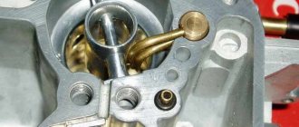
- Having removed the cover, we immediately determine the fuel level in the chambers by lowering a ruler or caliper into one of them until it stops (using its depth gauge). If the measurement shows a level of 25-26 mm, it corresponds to the norm and no adjustment is required;
If the amount of fuel in the chamber is lower or higher than normal, we perform a visual inspection and a series of measurements on the floats, and if necessary, we correct their position.
To carry out adjustment work, place the removed carburetor cover on a flat horizontal surface with the floats facing up.
First, we look at the position of the elements from above. The outer side surfaces of the floats are parallel to the special imprints on the gasket. Deviations can cause the floats to touch adjacent elements and surfaces, causing the fuel level to be incorrect. If necessary, adjust the position of the floats by bending their mounting arms. The next step is to measure the gap between the floats and the gasket. A rod with a diameter of 2 mm is useful here - this is how much the specified gap should be.
If it does not correspond, we bend the tongue of the floats, with which they act on the locking needle. After this adjustment, we check the total height of the floats, which is normally 34 mm. If this is not the case, check the gap again, adjust it if necessary and measure the height again.
The last stage of setup is determining the working stroke of the floats. To do this, place a caliper near the float, mark the distance from its lower corner to the surface of the cover, then lift the float with your hand and mark where the lower corner is.
A working stroke of 15 mm is considered normal; if it differs, it is adjusted by bending the tongue.
Alternative way
There is a simpler method for determining the correct position of the floats, which does not require measurements. Place the carburetor cover on a flat table and look at the stampings made on the side surfaces. When the floats are in a normally adjusted position, these strips are parallel to the lid.
Then we lift the floats up and look at their bottom, which after lifting should be parallel to the surface of the lid. If necessary, adjust the position of the floats by bending the tongue.
After adjustment work, we assemble the carburetor.
Idle speed adjustment
The second setting of the VAZ-2109 carburetor is idle speed, it can be partial or full. The first is for minor speed adjustments, the second is for adjusting the amount of air (setting CO emissions in the exhaust gases).
Partial adjustment is performed using the air-fuel mixture “amount” screw. This screw sets the opening angle of the throttle valves, which ensures that the air-fuel mixture enters the cylinders when the accelerator pedal is released. The “quantity” screw rests on the throttle valve control lever and when screwed in, it pushes the lever, causing the valves to open slightly.
Partial idle adjustment is performed with a warm engine and creating a load on the vehicle's on-board network by turning on the high beam headlights and the interior heater at full power. The adjustment is carried out with the engine running by screwing in/unscrewing the “quantity” screw until the optimal idle speed is established, which for the VAZ-2109 is 800-900 rpm (this can be tracked using a standard or plug-in tachometer).
If it is not possible to set the required speed or the motor operates unstably at it, a complete adjustment is made, which is made by two screws - “quantity” and “quality”.
The algorithm for this adjustment consists of the following stages:
- Warm up the engine and then turn it off;
- We find the quality screw (it may be closed with a plug that will have to be removed), screw it in until it stops, and then unscrew it 3-4 full turns;
- We start the engine, turn on electrical consumers (lighting and stove) to create a load in the on-board network;
- By rotating the “quantity” screw, we achieve 700-800 rpm on the tachometer;
- By turning the “quality” screw, we set the maximum possible speed (they will increase to a certain level, and then stop. The moment the speed increase stops is considered the maximum);
- We set the “quantity” screw to 900 rpm;
- Using the “quality” screw we lower them to 800 rpm;
- We slowly tighten the “quality” screw until interruptions appear in the operation of the power plant, after which we unscrew it back 1 turn;
- We adjust the speed with the “quantity” screw, bringing it to a normal value - 800-900 rpm;
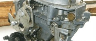
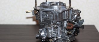
The design of the VAZ-2109 carburetor
The first front-wheel drive VAZ cars went into production in 1985. The Togliatti plant began producing three-door 2108 models equipped with a 1.3-liter gasoline engine. Somewhat later, conveyor production of 5-door “nines” was established, and new 1.1 and 1.5 liter engines (modifications 21081 and 21083) also appeared.
AvtoVAZ has developed its own carburetor for each engine size, but externally the CUs are practically no different from each other, the difference lies only in the metering elements located inside the body and the nameplate with the model designation. Unlike classic Ozones, Solexes have a body of only two parts, and not three - this is the main section with a platform for installation on the engine and the top cover.
The design of the VAZ-2109 carburetor has its own characteristics, but in general it contains the same parts as another similar unit for domestic passenger cars of the nineties and early two thousand. This HRSG is an emulsion type, two-chamber, with sequential opening of the chambers, for more stable operation it is equipped with liquid heating (antifreeze or antifreeze poured into the cooling system is used).
For full operation in any mode and optimal dosing of the air-fuel mixture, the following systems are provided:
- the main dosing one is the main one, its elements are present in both chambers (air and fuel supply nozzles, diffusers, emulsion tubes);
- idle speed (idle), ensures stable operation of the internal combustion engine at low speed, economical consumption of gasoline;
- transition from the first chamber to the second, serves to prevent jerks and failures when the valve of the second chamber opens;
- accelerator pump supplies an additional portion of fuel at the moment of sharp acceleration of the car, due to which the speed is gained smoothly, without jerking;
- economizer, enriches the fuel mixture at high speeds of the internal combustion engine (ICE) and increased loads;
- starting device allows the engine to start without problems in any cold weather:
- float chamber maintains the required level of gasoline regardless of load and speed.
When parts of the carburetor unit wear out, become clogged or fail, various malfunctions appear, such as loss of power, uneven engine operation, increased fuel consumption, engine stopping when releasing gas, etc. Only a specialist can independently deal with all the intricacies of the repair, but many drivers are able to clean, adjust and tune the carburetor with their own hands.
Causes of errors
The main reason why the fuel level may be displayed incorrectly on the instrument panel is long-term operation of the sensor.
Most often, the device is replaced with a similar one from another car model, for example, VAZ 21099, 2110. After the replacement, some drivers notice that the data is displayed incorrectly. Most often this happens if the sensor was removed from an earlier version of the car and installed on a later one, for example, from 2109 to 2110 model. In addition, incorrect data may also appear after installing the Europanel.
The reason may be in the contacts, but there is no exact solution, so if you want to change the sensor, then look for a similar model.
Another reason is a littered float. When this part of the device is left in gasoline for a long time without cleaning, it can become covered with a rather unpleasant coating. As a result, the structure becomes heavier, which leads to constantly overestimated performance, as well as to rapid breakdown of the lever and float. The float can be replaced, but only with exactly the same one, not a similar one.
Removing and installing the carburetor
Installation and dismantling is carried out in case of repair of this unit, its complete replacement, as well as for thorough washing and cleaning. The AHU can become clogged if the car is driven on dusty roads, as well as as a result of untimely replacement of the air filter element.
Removing and installing a VAZ-2109 carburetor is very simple; even with the initial skills of a car mechanic, almost any driver (car owner) can do such work with his own hands. We perform the dismantling operation as follows:
- turn off the ignition, open the hood, remove the top cover, the filter element, then unscrew the four nuts securing the air filter housing (AFC);
- loosening the clamps, disconnect the fuel hoses, unscrew the two fastenings of the choke cable, move the cable to the side, disconnect the wire chips of the solenoid valve and the throttle valve closing sensor;
- We also disconnect the throttle cable, having previously removed the return spring, the ignition angle advance hose, and unscrew the nuts securing the carburetor itself (also 4 pieces);
- in order not to lose antifreeze and not to disconnect the coolant pipes, it is easier to unscrew the screw securing the heating unit, but it is located at the back of the housing, not in the most accessible place;
- in this case, lift up the unscrewed carburetor, move it forward, find a position in which it would be convenient to dismantle this fastener;
- Now nothing prevents you from removing the entire assembly.
If the KU is thoroughly stuck to the studs and does not pull off, you can gently tap it at the base with a small hammer and shake it with your hands from side to side. As a rule, after several attempts the device gives in; after removing it, you can begin further planned operations; installation of the unit is carried out in the reverse order.
Functionality check
Do not rush to throw out the old sensor and replace it with a new regulator. First you can try to check if it really doesn't work.
To check, you will have to extract the “suspect” in any case.
- Inside the car, remove the lower part of the rear seat, remove the soundproofing material, if any. This will give you access to the inspection hatch in the floor of the car.
- Using a Phillips screwdriver, unscrew the four mounting screws that hold the hatch in place. Take it off. Under the hatch you will find a sealing gasket made of rubber. In any case, even if the old sensor works again for the benefit of your car, this gasket should be replaced.
- Disconnect the power supply block with wires from the sensor, and then unscrew the fastening nuts around the perimeter that hold the desired fuel level sensor on the tank body. Usually there are 6 of these nuts, and to dismantle them you will need an 8 socket socket or a regular wrench.
- Under one of the nuts there is a ground wire attached to a stud. Remove the wiring and put it aside for now. He shouldn't interfere.
- Carefully remove the sensor and do not forget to remove the rubber sealing gasket, which is located directly under the regulator. If there are signs of damage or defects on it, be sure to replace this component.
- When the sensor is removed, visually check its current condition. If there are mechanical damages, there is no point in further trying to repair it or restore its functionality. Change it right away.
- If there is no visual damage, check the condition of the float. It can be depressurized, that is, there is fuel inside it, cracks and various defects through which fuel has leaked are visible on the surface of the element. If all of this is present at the float, replace the entire sensor.
- Be sure to blow out the fuel filter with compressed air. A useful event that definitely will not harm your fuel system. Especially if the quality of gasoline with which you fill your VAZ 2109 leaves much to be desired.
- Check the condition of the resistor. To do this, you will need a multimeter in ohmmeter mode. Connect a measuring device to the sensor terminals and take readings. In the lowest position (empty tank), the resistance should be about 315-345 Ohms. If the tank is half full, the resistance will be 108-128 ohms. And when the tank is empty, the ohmmeter should show no more than 7 ohms. If the parameters differ from those specified, or there is no resistance at all, this indicates a malfunction of the controller. It must be replaced.
Basic faults
Any malfunctions of the 2109 carburetor affect the performance of the engine: the engine may stall when the speed is reduced, run intermittently, not develop power, and consume gasoline beyond the norm. There are many reasons for problems with this unit, but the most typical of them are:
- clogging of the HDS and idle jets, both air and fuel, and in the solenoid valve (EMV);
- rupture (defect) of the accelerator pump diaphragm;
- failure of the EMG itself;
- loose fit of the locking mechanism needle to the seat;
- air leakage through the junction of the body and the cover;
- leakage of the float in the float chamber;
- clogging of the accelerator pump nozzle with dirt;
- misadjustment of screws XX.
Of course, various types of malfunctions can occur not only due to the carburetor, the engine itself is often faulty, and the ignition may also be set incorrectly, especially if the installation was carried out by an inexperienced technician without a strobe light. Problems with idle speed can occur due to a lack of power to the solenoid valve, so before disassembling the HRV, you should first check for voltage on this wiring.
Operating principle
There is no point in examining in detail how a carburetor works, so let's study the basic principle of operation. A carburetor is a special device whose main task is to supply the engine with a fuel mixture in different operating modes.
The fuel mixture is supplied from the pump to the float chambers, which feed the first and second chambers. The gasoline level here is adjusted using a needle valve. Next, fuel is supplied from the chambers through special channels in the device body into the main jet and then into the first chamber. The mixture supply level is controlled by the accelerator pedal. The latter, in turn, regulates the throttle valve. The second camera will be activated if you press the gas pedal more than halfway.
When the engine is idling, the device does not use the main metering system. These carburetors have a separate idle design. Fuel and air are supplied through separate channels in the housing. XX jets are also present. Many owners have problems with setting the idle speed on VAZ-2109 carburetors.
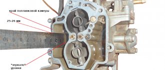
Adjusting the fuel level in the float chamber
Maintaining a normal level of gasoline in the float chamber is an important condition; if it is not met, malfunctions in the operation of the car occur:
- if the level is below normal, the engine does not have enough speed, power decreases, and gasoline consumption increases;
- if it is higher than required, fuel consumption also increases, and even more.
Setting the fuel level for the VAZ-2108-09-099 is quite simple, and in this case it is not at all necessary to remove the carburetor. The procedure for adjusting the position of the floats is as follows:
- remove the KVF assembly with the filter element;
- disconnect the choke cable, fuel hoses, EMG power cable;
- unscrew the five screws securing the carburetor cover;
- turn the lid over, take a drill with a thickness of 1 to 2 mm and take a measurement between the gasket and the lower surface of the floats - this distance should be exactly within these limits, and the same.
You can also measure the fuel level, but before carrying out such a procedure, it is necessary for the engine to idle for several minutes. The distance from the upper edge of the housing to the surface of the gasoline is measured; according to factory conditions, it should be 25-26 mm. Another way is to measure the distance from the gasket to the top edge of the floats with a caliper; it is 34 mm (with the cover upside down).
Another measurement method is using a specially made template.
Important conditions when setting the level:
- the floats must be located parallel to each other, along the lid;
- they are installed strictly vertically, without distortions;
- when lifting the float pair all the way up, the distance from their lower corners to the gasket should be within 15 mm;
- the adjustment of the extreme positions during adjustment is carried out by bending the tabs on both sides;
If the floats inside the chamber are installed skewed or not strictly vertical, they may rub against the walls of the housing, causing gasoline to overflow as a result of sticking.
Purchasing new equipment
Repairing old equipment is not difficult if it has become unusable due to oxidation or rust formation. Wiping the device can help restore contacts, but if the device is broken, even after restoration it may display incorrect data. If the error is more than 10%, then this can significantly affect the driver’s comfort behind the wheel, as well as the risk of being left with an empty tank on the road.
Therefore, if there is an error, it is recommended to replace it with a new device. Thus, the car owner can be confident in the accuracy of the data displayed on the dashboard. The cost of spare parts is relatively inexpensive; an injector can be found within 300 rubles. The part is easy to maintain and does not require replacement often, so it is recommended that if the data is inaccurate, replace it immediately.
Purchasing new equipment ensures that correct readings are displayed. By purchasing original spare parts, the car owner can forget about replacing them within 2-3 years.
Idle speed adjustment
The most common problem with a Solex carburetor is the disappearance of normal idle speed; the engine begins to operate intermittently at low speeds. Very often, the cause of such a malfunction is either a clogged EMG jet or the solenoid valve itself. It is very easy to check this - while the engine is running at idle, we disconnect the wiring from the EMG; if the nature of the internal combustion engine does not change at all, and when the valve is unscrewed, the speed increases noticeably, then the defect is present.
You can try to restore normal operation of the XX without removing the entire assembly, and this procedure is quite simple:
- With the engine off, remove the air filter with housing:
- disconnect the EMG wire, unscrew the valve itself;
- we start the engine, plugging the “idle” channel with a finger, “accelerate” several times;
- we stop the engine, do not forget to blow out the EMG and its nozzle using a compressor or hand pump, separating these parts from each other;
- we put the parts in place, do a test start of the internal combustion engine: if the idle speed has stabilized, and when the wiring was removed, the speed changed, it means that the reason was precisely the blockage, and now the idle speed has “returned to normal.”
But it is not always possible to clean the channel in this way; specks may get stuck in the area of the quality screw. Here you already need to remove and disassemble the carburetor, dismantle the screw, which in general is not very difficult, since it is located deep in the channel and is held there by a rubber sealing ring.
Adjusting the ignition angle
Sluggish acceleration of the car and instability of the idle speed are also often associated with incorrectly set ignition; this procedure is mainly carried out in car repair shops using special equipment. But if you wish, it’s easy to make the adjustment yourself, and without a strobe, and quite accurately:
- with the engine stopped, loosen the three nuts securing the distributor (the third fastening is located at the bottom, it is not visible from above);
- we start the car, turn the distributor-distributor clockwise (to “+”), and if the ignition was late, the idle speed will increase noticeably;
- we select the optimal position of the distributor (the operation of the internal combustion engine should be smooth, without failures), reduce the speed using the quantity screw, turn off the engine, fix the distributor-distributor with one nut for now, and check the results of the ignition adjustment on the fly.
If, under heavy load and sharp acceleration, your fingers begin to noticeably “knock” (engine detonation appears), you should move the distributor a little to “minus”, then check the car again while driving. This way you can set the ignition quite accurately, and sometimes even better than with a strobe light.
Signs of trouble
FLS failure does not happen often, but at some point it can take the driver by surprise. Incorrect gasoline readings can result in the car owner overfilling the car tank at a gas station or running dry on the road.
Although a breakdown is a rare occurrence for this device, it becomes immediately noticeable to the car owner. The appearance of problems with FLS manifests itself in a car as follows:
- The arrow, which shows the amount of gasoline in the gas tank, constantly remains at zero, even when refueling the car;
- The arrow indicates overestimated indicators. For example, a full tank is shown when it is only half full;
- The arrow indicates underestimated indicators. For example, when filling a full tank, the dashboard displays much less.
It is not necessary to get a new device if these problems arise. In some cases, it is possible to adjust it and resolve inaccuracies.
Features and malfunctions of the starting device
With the onset of frost, many owners of “nines” are faced with the problem of poor cold starting of the engine, and the cause of the malfunction is often the starting device (PU), which is designed to enrich the fuel mixture in a certain proportion. When the choke cable is pulled, the air damper closes, but under the influence of vacuum it changes its position, opening slightly and to some extent allowing air to pass into the carburetor. The position of the air intake is also adjusted using a diaphragm device, which is mechanically connected to the damper by a system of rods.
Quality screw removal method
With Solex carburetors, the XX channel in the body itself often becomes clogged, and in order to clear it thoroughly, it is necessary to remove the quality screw. But this screw, as mentioned above, has a very tight fit and is not easy to get out. There are several methods for dismantling a part; we will consider only one option.
We take a piece of an old antenna from any radio receiver, select the outer diameter so that the tube fits into the channel of the carburetor body, usually the outer thickness of the “puller” is about 4 mm. We cut off a small piece, make a cut at one end (about 1 cm deep), use another quality screw (a spare one, or you can buy it specially in a store), and check how tightly the tube fits onto the head of the screw.
Now you can unscrew the screw and use a homemade puller to remove it from the KU body.
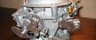
Adjusting carburetors is a delicate process and requires some caution. In order to obtain the desired result, the idle speed is usually adjusted. So, here is a standard carburetor for a VAZ 2109:
The “quantity” and “quality” screws with which the carburetor is calibrated are clearly visible here.
Fine adjustments are not made with the engine running. This is important - don't forget. What to do:
- Warm up the engine and turn it off.
- Take the mixture quality screw. First you need to tighten it to the limit. Then unscrew it four or five turns. As a result, we get a completely enriched mixture.
- Next, we do the same with the quantity screw, but unscrew it three turns.
- The preheated engine can now be started.
- Using the quantity screw you need to adjust the idle speed. The limit is 800 rpm.
- Now, slowly tighten the mixture quality screw. An important point is that the gas distribution mechanism, ignition and the carburetor itself must be in good working order!
- We adjust the speed further. They will grow a little at first. Then they will become less stable. As you continue to tighten the screw, they will become smaller. As soon as you notice that the speed is unstable, you can unscrew the screw half a turn.
- Next, we correct the speed using the quantity screw. Don't forget to check the number of revolutions under increased loads - with the oven on, for example. In winter, even from the usual 850 rpm, you should raise it to 1000.
DIY repair
If the sensor is equipped with a porous component, there are several options for changing it:
- You can remove it from the retainer socket and install a new one, securing it.
- Or replace the float itself along with the rod.
The second option is more preferable because it is easy to implement. If the surface of the strip on the rheostat scale is dirty, the element is cleaned.
The cleaning procedure is performed exclusively with cotton wool or a soft cloth pre-treated with alcohol. The use of harsh materials or other products is not permitted. This will damage the working layer of the scale; it is quite thin, so it can cause the rheostat to break. The element cannot be repaired; it will have to be replaced.
If the contacts of the electrical circuit come off the controller, they must be carefully soldered back or connected at the point of damage. Plates with mechanical damage (cracks, fractures) cannot be repaired, only replaced. If the sensor gives incorrect readings, the problem can be corrected by adjusting the angle on the so-called rod. This element is designed to fix the float. To get accurate readings, the angle is bent in different directions.