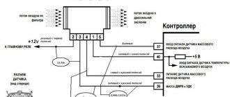
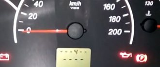
Tired of looking for error codes every time? The on-board computers presented above will SOLVE your problem!
Reading, decoding, removing errors without leaving the car!
Decoding error codes issued by the ECU of GAZ, GAZelle, Sobol, Volga cars
- 012 — The unit’s self-diagnosis mode is turned on (short circuit of the L-line to ground).
- 013 - Low signal level of the mass air flow sensor (MAF).
- 014 - High signal level of the mass air flow sensor (MAF).
- 015 - Low signal level of the absolute air pressure sensor (DAP).
- 016 - High signal level of the absolute air pressure sensor (DAP).
- 017 — Low signal level of the air temperature sensor (DTV).
- 018 - High signal level of the air temperature sensor (DTV).
- 019 - Engine overheating (coolant temperature above 105°C).
- 021 - Low signal level of the coolant temperature sensor (DTOZH).
- 022 - High signal level of the coolant temperature sensor (DTOZH).
- 023 - Low signal level of the throttle position sensor (TPS).
- 024 - High signal level of the throttle position sensor (TPS).
- 025 - Low voltage level in the on-board network.
- 026 - High voltage level in the on-board network.
- 027 - Only for MIKAS: Malfunction of the DPKV or secondary ignition circuits.
- 027 - Only for AUTRON: Incorrect initial setting of the throttle position sensor (TPS).
- 028 - Only for MIKAS: Malfunction of the DPKV or secondary ignition circuits.
- 028 - Only for AUTRON: The crankshaft speed has exceeded the maximum.
- 029 - Only for MIKAS: Malfunction of the DPKV or secondary ignition circuits.
- 029 - Only for AUTRON: Incorrect connection of the crankshaft speed sensor.
- 031 — Low signal level of the (first) CO corrector.
- 032 — High signal level of the (first) CO corrector.
- 033 - Low signal level of the second CO corrector.
- 034 - High signal level of the second CO corrector.
- 035 - Low signal level of the main (first) lambda probe (oxygen sensor).
- 036 - High signal level of the main (first) lambda probe (oxygen sensor).
- 037 - Low signal level of the additional (second) lambda probe (oxygen sensor).
- 038 - High signal level of the additional (second) lambda probe (oxygen sensor).
- 041 - Malfunction of the (first) knock sensor (DS) circuit.
- 042 - Malfunction of the second knock sensor (DS) circuit.
- 043 - Low signal level of the recirculation valve position sensor.
- 044 - High signal level of the recirculation valve position sensor.
- 045 - Low signal level of the canister valve position sensor.
- 046 - High signal level of the canister valve position sensor.
- 047 - Low signal level of the power steering sensor (power steering).
- 048 - High signal level of the power steering sensor (power steering).
- 051 - Malfunction of 1 control unit.
- 052 - Malfunction of control unit 2.
- 053 - Malfunction of the crankshaft position sensor (CPS).
- 054 - Malfunction of the camshaft position sensor (DPRV).
- 055 - Malfunction of the vehicle speed sensor (VS).
- 056 - Short circuit of the ignition coil circuit of cylinders 1/4 (for AUTRON units).
- 057 - Short circuit of the ignition coil circuit of cylinders 2/3 (for AUTRON units).
- 058 — Open circuit of the crankshaft position sensor (for AUTRON units).
- 061 - Reset the control unit in working condition.
- 062 - Malfunction of the control unit's random access memory (RAM).
- 063 - Malfunction of the control unit's permanent memory (ROM).
- 064 - Malfunction when reading the flash RAM of the control unit (EEPROM).
- 065 - Malfunction when writing to the flash RAM of the control unit (EEPROM).
- 066 - Malfunction when reading the control unit identification code.
- 067 - Malfunction of 1 immobilizer.
- 068 - Malfunction of immobilizer 2.
- 069 - Malfunction of immobilizer 3.
- 071 - Low idle speed.
- 072 - High idle speed.
- 073 - Rich mixture signal from lambda probe 1 at maximum leanness.
- 074 - Lean mixture signal from lambda probe 1 at maximum enrichment.
- 075 - Rich mixture signal from lambda probe 2 at maximum leanness.
- 076 - Lean mixture signal from lambda probe 2 at maximum enrichment.
- 079 — Malfunction when adjusting the recirculation valve using the sensor.
- 081 - Maximum displacement of the ignition timing (IAF) by detonation in cylinder 1.
- 082 - Maximum displacement of the ignition timing (IAF) by detonation in cylinder 2.
- 083 - Maximum displacement of the ignition timing (IAF) by detonation in cylinder 3.
- 084 - Maximum displacement of the ignition timing (IAF) by detonation in cylinder 4.
- 085 - Maximum displacement of the ignition timing (IAF) by detonation in cylinder 5.
- 086 - Maximum displacement of the ignition timing (IAF) by detonation in cylinder 6.
- 087 - Maximum displacement of the ignition timing (IAF) by detonation in cylinder 7.
- 088 - Maximum displacement of the ignition timing (IAF) by detonation in cylinder 8.
- 091 - Short circuit to the on-board network in ignition circuit 1.
- 092 - Short circuit to the on-board network in ignition circuit 2.
- 093 - Short circuit to the on-board network in ignition circuit 3.
- 094 - Short circuit to the on-board network in ignition circuit 4.
- 095 - Short circuit to the on-board network in ignition circuit 5.
- 096 - Short circuit to the on-board network in ignition circuit 6.
- 097 - Short circuit to the on-board network in ignition circuit 7.
- 098 - Short circuit to the on-board network in circuit 8 of the ignition.
- 099 - Malfunction of the high voltage driver.
- 131 - Short circuit to the on-board network of injector circuit 1.
- 132 - Open circuit or short to ground in injector 1 circuit.
- 133 - Short circuit to ground in injector 1 circuit.
- 134 - Short circuit to the on-board network of injector circuit 2.
- 135 - Open circuit or short to ground in injector 2 circuit.
- 136 - Short circuit to ground in injector 2 circuit.
- 137 - Short circuit to the on-board network of injector circuit 3.
- 138 - Open circuit or short to ground in injector circuit 3.
- 139 - Short circuit to ground in injector 3 circuit.
- 141 - Short circuit to the on-board network of injector circuit 4.
- 142 - Open circuit or short to ground in injector 4 circuit.
- 143 - Short circuit to ground in injector 4 circuit.
- 144 - Short circuit to the on-board network of injector circuit 5.
- 145 - Open circuit or short to ground in injector circuit 5.
- 146 - Short circuit to ground in injector circuit 5.
- 147 - Short circuit to the on-board network of injector circuit 6.
- 148 - Open circuit or short to ground in injector 6 circuit.
- 149 - Short circuit to ground in injector 6 circuit.
- 151 - Short circuit to the on-board network of injector circuit 7.
- 152 - Open circuit or short to ground in injector 7 circuit.
- 153 - Short circuit to ground in injector 7 circuit.
- 154 - Short circuit to the on-board network of injector circuit 8.
- 155 - Open circuit or short to ground in injector circuit 8.
- 156 - Short circuit to ground in injector circuit 8.
- 157 - Short circuit to the on-board network of the starting injector circuit.
- 158 - Open or short to ground in the starting injector circuit.
- 159 - Short circuit to ground in the starting injector circuit.
- 161 - Short circuit to the on-board network of control circuit 1 of the additional air regulator (RDV or IAC).
- 162 - Open circuit or short to ground in control circuit 1 of the additional air regulator (RDV or IAC).
- 163 - Short circuit to ground in control circuit 1 of the additional air regulator (RDV or IAC).
- 164 - Short circuit to the on-board network of control circuit 2 of the additional air regulator (RDV or IAC).
- 165 - Open circuit or short to ground in control circuit 2 of the additional air regulator (RDV or IAC).
- 166 - Short circuit to ground in control circuit 2 of the additional air regulator (RDV or IAC).
- 167 - Short circuit to the on-board network of the electric fuel pump relay circuit.
- 168 — Open circuit or short to ground in the electric fuel pump relay circuit.
- 169 - Short circuit to ground in the electric fuel pump relay circuit.
- 171 - Short circuit to the on-board network of the recirculation valve circuit.
- 172 - Open circuit or short to ground in the recirculation valve circuit.
- 173 - Short circuit to ground in the recirculation valve circuit.
- 174 - Short circuit to the on-board network of the canister valve circuit.
- 175 - Open circuit or short to ground in the canister valve circuit.
- 176 - Short circuit to ground in the canister valve circuit.
- 177 — Short circuit to the main relay circuit on-board.
- 178 - Open circuit or short to ground in the main relay circuit.
- 179 - Short circuit to ground in the main relay circuit.
- 181 - Short circuit to the on-board network of the malfunction lamp circuit (Check Engine).
- 182 - Open circuit or short to ground in the fault lamp circuit (Check Engine).
- 183 - Short circuit to ground in the fault lamp circuit (Check Engine).
- 184 - Short circuit to the tachometer circuit.
- 185 - Open or short to ground tachometer circuit.
- 186 - Short circuit to ground in the tachometer circuit.
- 187 - Short circuit to the on-board network of the fuel flow meter circuit.
- 188 — Open or short to ground in the fuel flow meter circuit.
- 189 - Short circuit to ground in the fuel flow meter circuit.
- 191 - Short circuit to the on-board network of the air conditioner relay circuit.
- 192 - Open or short to ground in the air conditioner relay circuit.
- 193 - Short circuit to ground in the air conditioning relay circuit.
- 194 — Short circuit to the on-board network of the cooling fan relay circuit.
- 195 — Open or short to ground in the cooling fan relay circuit.
- 196 - Short circuit to ground in the cooling fan relay circuit.
- 197 - Short circuit to the on-board network of the EPHH valve circuit.
- 198 — Open circuit or short to ground in the EPH valve circuit.
- 199 — Short circuit to ground in the EPH valve circuit.
- 231 - Open circuit or short to ground in ignition circuit 1.
- 232 - Open circuit or short to ground in ignition circuit 2.
- 233 - Open circuit or short to ground in ignition circuit 3.
- 234 - Open circuit or short to ground in ignition circuit 4.
- 235 - Open circuit or short to ground in ignition circuit 5.
- 236 - Open circuit or short to ground in ignition circuit 6.
- 237 - Open circuit or short to ground in ignition circuit 7.
- 238 - Open circuit or short to ground in ignition circuit 8.
- 241 - Short circuit to ground in ignition circuit 1.
- 242 - Short circuit to ground in ignition circuit 2.
- 243 - Short circuit to ground in ignition circuit 3.
- 244 - Short circuit to ground in ignition circuit 4.
- 245 - Short circuit to ground in ignition circuit 5.
- 246 - Short circuit to ground in ignition circuit 6.
- 247 - Short circuit to ground in ignition circuit 7.
- 248 - Short circuit to ground in ignition circuit 8.
- 251 — Short circuit to the on-board network of the mass air flow sensor burning circuit.
- 252 — Open or short to ground in the burning circuit of the mass air flow sensor.
- 253 - Short circuit to ground in the burning circuit of the mass air flow sensor.
History of creation
The OBD system was developed in the 1980s in the United States of America. Initially, it was conceived only to control exhaust emissions. The chairmen of the California Air Resources Board have begun to develop a new environmental standard for the country's cars. To control the safety of the vehicle, a special device was inserted into the control panel, onto which the necessary data was saved.
Then they could be counted and conclusions drawn about the safety of the car for the environment. Later, in 1988, development of a new system began. Vehicles that meet all OBD-2 requirements have been produced since 1994. The new system came into full force in 1996. It became mandatory for all passenger cars manufactured and sold in the United States.
In Europe, the system was adopted as the basis for creating requirements for the environmental safety of machines. Some European car manufacturers began using a 16-pin connector for OBD-2 testers in 1995.
What does the system consist of?
Important! The concept of OBD2 includes several elements.
This abbreviation should be understood as:
- Connectors for connecting special devices. Devices that monitor the condition of the vehicle are inserted into them and collect data.
- Connections. This could include wires, speakers, or any other device connections. Modern testers connect to the phone via Bluetooth or WI-FI.
- A command system for data exchange between the electronic control unit and diagnostic devices.
- Device connector standards.
- Testers. These are special devices that can be purchased in the store. They are necessary to activate the system and communicate with your phone or tablet.
All elements form a single diagnostic system. It is able to identify problems occurring in the car and notify the driver about it.
How to connect the system?
To activate the on-board diagnostic system, you need to buy a special tester. It can be ordered from many online stores. It is important that the device is original.
Important! Fake testers may not connect to your phone or other device.
The system can be controlled from a phone or any other device. To do this, you need to install a special application on your device. In it you can see all the indicators that are transmitted from the tester. If an emergency situation occurs (a breakdown in the car), the OBD-2 on-board diagnostic system will analyze what happened to the vehicle and issue an error code.
All necessary information regarding the malfunction will immediately be sent to the gadget. To view the message, you need to open the application and write down the code that the system will issue. You can decrypt it yourself, using the Internet. Then you need to take the car to a car service center and report the breakdown.
Diagnosis of car errors
You can diagnose a car yourself not only using a computer, but also using mobile applications on the Android or Apple platform. There are many different applications on the Internet for this procedure, some of them can read vehicle code errors, find the cause and eliminate them. For example, for the OBD-II scanner there are special programs for Android that will tell you about all the car error codes and methods for eliminating them. In order to download it, you need to enter the name of the application on the play market “Deciphering OBD-II error codes”. In these programs you will find a lot of useful things, but the main thing is that the database contains all the car error codes.
If you use an Apple phone, then there is simply an ideal application for you to know what error codes are in your car, the program itself eliminates or deletes them. The application is sold with a cable for connection to the car. GoPoint Techonogy – works with GL-1 and BT-1 scanners. The scanner data and applications are official Apple applications, where GL-1 is a cable for connecting the car to the phone, and BT is a Bluetooth transmitter. The program not only helps eliminate car code errors, but also checks the operation of the engine, all sensors and much more. These two scanner-transmitters not only work with the native GoPoint Techonogy program, but are also compatible with DashCommand.
There are many applications, programs, scanners with which you can identify car error codes and eliminate them yourself. These maintenance services will cost a lot of money, but why pay for something you can do yourself? To use these applications, it is not necessary to have a professional level of computers and gadgets; you just need to know how to install the application. And may your car last for many years!
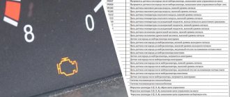
How to find out about a malfunction?
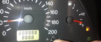
If any breakdown occurs in the car, a special sign will light up on the dashboard. Its name is Check Engine. Literally translated, it means “check engine.” Almost every driver has encountered this signal on their dashboard.
Check engine
The sign notifies that a malfunction has been detected in the vehicle’s power unit. You can check what's wrong using the OBD-2 system. You can reset the error using the app. In this case, the sign on the panel will stop lighting.
Important! When the Check Engine light is on, you need to get an error code and fix the problem at a car service center.
OBD-2 capabilities
Detecting faults in a car is not all that the OBD-2 system is capable of. Using on-board diagnostics you can:
- Monitor work through the electronic control unit and monitor indicators. The screen of the device on which a special application is installed will display data regarding the condition of the engine and the health of its operation.
- Analyze the performance of the vehicle's power supply network. You can also monitor individual elements of this system, for example, fuel supply.
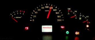
- Control emissions of exhaust gases into the atmosphere. If the amount of toxic substances produced by a car exceeds the state limit by 1.5 times, the MIL gauge on the dashboard lights up. The indicator informs the driver that his vehicle poses a danger to the environment.
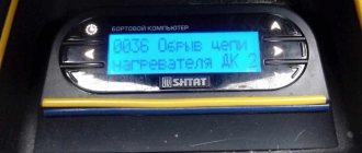
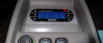
Error monitoring display
Obd2 error codes: decoding in Russian
| CODE | Description of the error |
| P0100 | Air flow sensor circuit malfunction |
| P0101 | The air flow sensor signal is out of the permissible range |
| P0102 | Low air flow sensor output level |
| P0103 | High output signal from the air flow sensor |
| P0105 | Air pressure sensor malfunction |
| P0106 | The air pressure sensor signal is out of the permissible range |
| P0107 | Air pressure sensor output low |
| P0108 | Air pressure sensor output high |
| P0110 | Intake air temperature sensor malfunction |
| P0111 | Intake air temperature sensor signal output is out of acceptable range |
| P0112 | Low level of intake air temperature sensor |
| P0113 | Intake air temperature sensor high level |
| P0115 | Coolant temperature sensor malfunction |
| P0116 | Coolant temperature sensor signal output is out of acceptable range |
| P0117 | Coolant temperature sensor low level |
| P0118 | Coolant temperature sensor high level |
| P0120 | Throttle position sensor "A" malfunction |
| P0121 | Throttle position sensor “A” signal output is out of range |
| P0122 | Throttle Position Sensor "A" Output Low |
| P0123 | Throttle Position Sensor "A" High Output |
| P0125 | Low coolant temperature for closed loop control |
| P0130 | Oxygen sensor 1 (bank 1) is faulty |
| P0131 | Low signal level of oxygen sensor 1 (bank 1) |
| P0132 | High signal level of oxygen sensor 1 (bank 1) |
| P0133 | Slow response of oxygen sensor 1 (bank 1) to rich/lean |
| P0134 | Oxygen sensor 1 output signal inactive (bank 1) |
| P0135 | Oxygen sensor 1 heater (bank 1) is faulty |
| P0136 | Oxygen sensor 2 (bank 1) faulty |
| P0137 | O2 Sensor 2 Output Low (Bank 1) |
| P0138 | Oxygen Sensor 2 Output High (Bank 1) |
| P0139 | Slow response of oxygen sensor 2 (bank 1) to rich/lean |
| P0140 | Oxygen Sensor 2 Output No Activity (Bank 1) |
| P0141 | Oxygen sensor 2 heater (bank 1) is faulty |
| P0142 | Oxygen sensor 3 (bank 1) faulty |
| P0143 | O2 Sensor 3 Output Low (Bank 1) |
| P0144 | Oxygen Sensor 3 Output High (Bank 1) |
| P0145 | Slow response of oxygen sensor 3 (bank 1) to rich/lean |
| P0146 | O2 Sensor 3 Output No Activity (Bank 1) |
| P0147 | Oxygen sensor 3 heater (bank 1) is faulty |
| P0150 | Oxygen sensor 1 (bank 2) is faulty |
| P0151 | Low signal level of oxygen sensor 1 (bank 2) |
| P0152 | High signal level of oxygen sensor 1 (bank 2) |
| P0153 | Slow response of oxygen sensor 1 (bank 2) to rich/lean |
| P0154 | No oxygen sensor 1 output activity (bank 2) |
| P0155 | Oxygen sensor 1 heater (bank 2) is faulty |
| P0156 | Oxygen sensor 2 (bank 2) is faulty |
| P0157 | O2 Sensor 2 Output Low (Bank 2) |
| P0158 | Oxygen Sensor 2 Output High (Bank 2) |
| P0159 | Slow response of oxygen sensor 2 (bank 2) to rich/lean |
| P0160 | No oxygen sensor 2 output activity (bank 2) |
| P0161 | Oxygen sensor 2 heater (bank 2) is faulty |
| P0162 | Oxygen sensor 3 (bank 2) faulty |
| P0163 | O2 Sensor 3 Output Low (Bank 2) |
| P0164 | Oxygen Sensor 3 Output High (Bank 2) |
| P0165 | Slow response of oxygen sensor 3 (bank 2) to rich/lean |
| P0166 | Oxygen Sensor 3 Output No Activity (Bank 2) |
| P0167 | Oxygen sensor 3 heater (bank 2) is faulty |
| P0171 | The mixture is too lean (possible air leaks) |
| P0172 | Mixture too rich |
| P0173 | Fuel leak from the fuel system of cylinder block No. 2 |
| P0174 | Cylinder block No. 2 mixture is too lean |
| P0175 | Cylinder block No. 2 mixture is too rich |
| P0176 | CHx emission sensor (Fuel Composition) is faulty |
| P0177 | CHx (Fuel Composition) sensor signal is out of range |
| P0178 | Low signal level of the CHx sensor (Fuel Composition) |
| P0179 | High signal level of the CHx sensor (Fuel Composition) |
| P0180 | Malfunction of the fuel temperature sensor circuit “A” |
| P0181 | Fuel temperature sensor signal “A” is out of acceptable range |
| P0182 | Low signal level of fuel temperature sensor “A” |
| P0183 | High signal level of fuel temperature sensor “A” |
| P0185 | Malfunction of the fuel temperature sensor circuit "B" |
| P0186 | Fuel temperature sensor signal “B” is outside the permissible range |
| P0187 | Low signal level of fuel temperature sensor “B” |
| P0188 | High signal level of fuel temperature sensor “B” |
| P0190 | Malfunction of the fuel pressure sensor circuit in the fuel rail |
| P0191 | Fuel rail pressure sensor signal is out of range |
| P0192 | Low signal from the fuel pressure sensor in the fuel rail |
| P0193 | High signal from the fuel pressure sensor in the fuel rail |
| P0194 | Intermittent signal from the fuel pressure sensor in the fuel rail |
| P0195 | Engine oil temperature sensor circuit malfunction |
| P0196 | Engine oil temperature sensor signal is out of range |
| P0197 | Low signal from engine oil temperature sensor |
| P0198 | Engine oil temperature sensor signal high |
| P0199 | Intermittent engine oil temperature sensor signal |
| P0200 | Injector control circuit malfunction |
| P0201 | No. 1 injector control circuit malfunction |
| P0202 | No. 2 injector control circuit malfunction |
| P0203 | No. 3 injector control circuit malfunction |
| P0204 | No. 4 injector control circuit malfunction |
| P0205 | No. 5 injector control circuit malfunction |
| P0206 | No. 6 injector control circuit malfunction |
| P0207 | No. 7 injector control circuit malfunction |
| P0208 | No. 8 injector control circuit malfunction |
| P0209 | No. 9 injector control circuit malfunction |
| P0210 | No. 10 injector control circuit malfunction |
| P0211 | No. 11 injector control circuit malfunction |
| P0212 | No. 12 injector control circuit malfunction |
| P0213 | No. 1 cold start injector control circuit malfunction |
| P0214 | Cold start injector control circuit fault No. 2 |
| P0215 | Engine shutdown solenoid malfunction |
| P0216 | Injection timing control circuit malfunction |
| P0217 | Engine overheating |
| P0218 | Transmission overheating |
| P0219 | Engine Overspeed Condition: Engine Overspeed Condition |
| P0220 | Throttle position sensor "B" malfunction |
| P0221 | Throttle Position Sensor "B" Signal Out of Range |
| P0222 | Low signal level of the throttle position sensor "B" |
| P0223 | Throttle Position Sensor "B" High Signal |
| P0224 | Throttle Position Sensor “B” Intermittent Signal Level |
| P0225 | Malfunction of the throttle position sensor "C" |
| P0226 | Throttle Position Sensor Signal Out of Range "C" |
| P0227 | Low signal level of the throttle position sensor “C” |
| P0228 | Throttle position sensor "C" high signal level |
| P0229 | Throttle position sensor “C” intermittent signal level |
| P0230 | Malfunction of the primary fuel pump control circuit (fuel pump relay control) |
| P0231 | Constant low level of the fuel pump secondary circuit |
| P0232 | Constant high level of the fuel pump secondary circuit |
| P0233 | Intermittent level of the fuel pump secondary circuit |
| P0235 | Turbocharger Pressure Sensor "A" Circuit Malfunction |
| P0236 | Signal from turbine sensor “A” is out of range |
| P0237 | Low signal level from turbine sensor “A” |
| P0238 | High signal level from turbine sensor “A” |
| P0239 | Turbocharger Pressure Sensor "B" Circuit Malfunction |
| P0240 | The signal from the turbine sensor “B” is out of range |
| P0241 | Low signal level from turbine sensor “B” |
| P0242 | High signal level from turbine sensor “B” |
| P0243 | Turbine "A" exhaust shutter solenoid malfunction |
| P0244 | Turbine "A" exhaust gas shutter solenoid signal is out of add. range |
| P0245 | Turbine "A" exhaust shutter solenoid is always open |
| P0246 | Turbine "A" exhaust shutter solenoid is always closed |
| P0247 | Turbine "B" exhaust shutter solenoid malfunction |
| P0248 | Turbine "B" exhaust gas shutter solenoid signal is out of add. range |
| P0249 | Turbine "B" exhaust shutter solenoid is always open |
| P0250 | Turbine "B" exhaust shutter solenoid is always closed |
| P0251 | Faulty turbine injection pump "A" |
| P0252 | Turbine injection pump signal “A” is out of range |
| P0253 | Low signal level of turbine injection pump “A” |
| P0254 | High signal level of turbine injection pump “A” |
| P0255 | Intermittent signal level of turbine injection pump “A” |
| P0256 | Failure of the injection pump of turbine "B" |
| P0257 | Turbine "B" injection pump signal is out of range |
| P0258 | Low signal level of turbine injection pump “B” |
| P0259 | Turbine injection pump “B” high signal level |
| P0260 | Intermittent signal level of turbine injection pump “B” |
| P0261 | Cylinder No. 1 injector - short to ground |
| P0262 | Cylinder No. 1 injector - open or short to +12V |
| P0263 | Cylinder No. 1 injector - injector driver malfunction |
| P0264 | Cylinder No. 2 injector - short to ground |
| P0265 | Cylinder No. 2 injector - open or short to +12V |
| P0266 | Cylinder No. 2 injector - injector driver malfunction |
| P0267 | Cylinder No. 3 injector - short to ground |
| P0268 | Cylinder No. 3 injector - open or short to +12V |
| P0269 | Cylinder No. 3 injector - injector driver malfunction |
| P0270 | Cylinder No. 4 injector - short to ground |
| P0271 | Cylinder No. 4 injector - open or short to +12V |
| P0272 | Cylinder No. 4 injector - injector driver malfunction |
| P0273 | Cylinder No. 5 injector - short to ground |
| P0274 | Cylinder No. 5 injector - open or short to +12V |
| P0275 | Cylinder No. 5 injector - injector driver malfunction |
| P0276 | Cylinder No. 6 injector - short to ground |
| P0277 | Cylinder No. 6 injector - open or short to +12V |
| P0278 | Cylinder No. 6 injector - injector driver malfunction |
| P0279 | Cylinder No. 7 injector - short to ground |
| P0280 | Cylinder No. 7 injector - open or short to +12V |
| P0281 | Cylinder No. 7 injector - injector driver malfunction |
| P0282 | Cylinder No. 8 injector - short to ground |
| P0283 | Cylinder No. 8 injector - open or short to +12V |
| P0284 | Cylinder No. 8 injector - injector driver malfunction |
| P0285 | Cylinder No. 9 injector - short to ground |
| P0286 | Cylinder No. 9 injector - open or short to +12V |
| P0287 | Cylinder No. 9 injector - injector driver malfunction |
| P0288 | Cylinder No. 10 injector - short to ground |
| P0289 | Cylinder No. 10 injector - open or short to +12V |
| P0290 | Cylinder No. 10 injector - injector driver malfunction |
| P0291 | Cylinder No. 11 injector - short to ground |
| P0292 | Cylinder No. 11 injector - open or short to +12 |
| P0293 | Cylinder No. 11 injector - injector driver malfunction |
| P0294 | Cylinder No. 12 injector - short to ground |
| P0295 | Cylinder No. 12 injector - open or short to +12V |
| P0296 | Cylinder No. 12 injector - injector driver malfunction |
| P0300 | Random/multiple misfires detected |
| P0301 | Misfire detected in cylinder No. 1 |
| P0302 | Misfire detected in cylinder No. 2 |
| P0303 | Misfire detected in cylinder No. 3 |
| P0304 | Misfire detected in cylinder No. 4 |
| P0305 | Misfire detected in cylinder No. 5 |
| P0306 | Misfire detected in cylinder No. 6 |
| P0307 | Misfire detected in cylinder No. 7 |
| P0308 | Misfire detected in cylinder No. 8 |
| P0309 | Misfire detected in cylinder No. 9 |
| P0310 | Misfire detected in cylinder No. 10 |
| P0311 | Misfire detected in cylinder No. 11 |
| P0312 | Misfire detected in cylinder No. 12 |
| P0320 | Ignition distributor circuit malfunction |
| P0321 | Ignition distributor signal out of range |
| P0322 | There is no signal from the ignition distributor |
| P0323 | Ignition distributor signal intermittent |
| P0325 | No. 1 knock sensor circuit malfunction |
| P0326 | Knock sensor signal No. 1 is out of range |
| P0327 | Low signal level of knock sensor No. 1 |
| P0328 | High signal level of knock sensor No. 1 |
| P0329 | Intermittent signal level of knock sensor No. 1 |
| P0330 | No. 2 knock sensor circuit malfunction |
| P0331 | Knock sensor signal No. 2 is out of range |
| P0332 | Low signal level of knock sensor No. 2 |
| P0333 | High signal level of knock sensor No. 2 |
| P0334 | Intermittent signal level of knock sensor No. 2 |
| P0335 | Crankshaft position sensor error "A" |
| P0336 | DPKV error “A” (missing one tooth) |
| P0337 | Low level or short to ground DPKV “A” |
| P0338 | High level or short circuit to +12V DPKV “A” |
| P0339 | Intermittent signal DPKV “A” |
| P0340 | Camshaft sensor malfunction |
| P0341 | Camshaft sensor signal out of range |
| P0342 | Camshaft sensor signal low |
| P0343 | Camshaft sensor signal high |
| P0344 | Intermittent camshaft sensor signal level |
| P0350 | Ignition coil primary/secondary circuit malfunction |
| P0351 | Ignition Coil "A" Primary/Secondary Circuit Malfunction |
| P0352 | Ignition Coil "B" Primary/Secondary Circuit Malfunction |
| P0353 | Ignition Coil "C" Primary/Secondary Circuit Malfunction |
| P0354 | Ignition coil "D" primary/secondary circuit malfunction |
| P0355 | Ignition coil "E" primary/secondary circuit malfunction |
| P0356 | Malfunction of the primary / secondary circuit of the ignition coil "F" |
| P0357 | Ignition coil "G" primary/secondary circuit malfunction |
| P0358 | Ignition coil "H" primary/secondary circuit malfunction |
| P0359 | Malfunction of primary/secondary circuit of ignition coil "I" |
| P0360 | Ignition coil "J" primary/secondary circuit malfunction |
| P0361 | Ignition coil "K" primary/secondary circuit malfunction |
| P0362 | Ignition coil "L" primary/secondary circuit malfunction |
| P0370 | Timer signal A fault |
| P0371 | The number of timer signal A pulses is higher than normal |
| P0372 | The number of timer signal A pulses is below normal |
| P0373 | Unstable pulses of timer signal A |
| P0374 | No timer signal A pulses |
| P0375 | Timer signal B fault |
| P0376 | The number of timer signal B pulses is higher than normal |
| P0377 | The number of timer signal B pulses is below normal |
| P0378 | Unstable Timer B Signal Pulses |
| P0379 | No timer signal A pulses |
| P0380 | Faulty glow plug or heating circuit |
| P0381 | Faulty glow plug or heat indicator |
| P0385 | Crankshaft Position Sensor "B" Circuit Malfunction |
| P0386 | Crankshaft Position Sensor "B" Signal Out of Range |
| P0387 | Low level or short to ground DPKV “B” |
| P0388 | High level or short circuit to +12V DPKV “B” |
| P0389 | Intermittent signal from crankshaft position sensor "B" |
| P0400 | Exhaust gas recirculation system malfunction |
| P0401 | Inefficiency of the exhaust gas recirculation system |
| P0402 | Exhaust gas recirculation (EG) system redundancy |
| P0403 | Exhaust gas recirculation sensor circuit malfunction |
| P0404 | EGR sensor signal is out of range |
| P0405 | Low signal level of sensor “A” of the exhaust gas recirculation system |
| P0406 | High signal level of sensor “A” of the exhaust gas recirculation system |
| P0407 | Low signal level of sensor “B” of the exhaust gas recirculation system |
| P0408 | High signal level of sensor “B” of the exhaust gas recirculation system |
| P0410 | Malfunction of the secondary air supply system |
| P0411 | Incorrect flow through the secondary air system |
| P0412 | Malfunction of the secondary air supply valve "A" |
| P0413 | Secondary air valve "A" is always open |
| P0414 | Secondary air valve "A" is always closed |
| P0415 | Malfunction of the valve of the secondary air supply system “B” |
| P0416 | Secondary air supply valve “B” is always open |
| P0417 | Secondary air supply valve “B” is always closed |
| P0420 | The efficiency of the B1 catalyst system is below the permissible threshold |
| P0421 | The heating efficiency of B1 catalysts is below the permissible threshold |
| P0422 | The efficiency of the main catalyst B1 is below the permissible threshold |
| P0423 | Catalyst heater efficiency B1 is below acceptable threshold |
| P0424 | The temperature of the catalyst heater B1 is below the permissible threshold |
| P0430 | The efficiency of the B2 catalyst system is below the permissible threshold |
| P0431 | The heating efficiency of B3 catalysts is below the permissible threshold |
| P0432 | The efficiency of the main catalyst B2 is below the permissible threshold |
| P0433 | Catalyst B2 heater efficiency below acceptable threshold |
| P0434 | The temperature of the catalyst heater B2 is below the permissible threshold |
| P0440 | Malfunction of the gasoline vapor recovery system control |
| P0441 | Poor purging of the gasoline vapor recovery system |
| P0442 | Small leak in the gasoline vapor recovery system |
| P0443 | Malfunction of the gasoline vapor recovery system purge valve circuit |
| P0444 | The gasoline vapor recovery system purge valve is always open |
| P0445 | The gasoline vapor recovery system purge valve is always closed |
| P0446 | Control malfunction vapor recovery system air valve |
| P0447 | Vapor recovery system air valve is always open |
| P0448 | The vapor recovery system air valve is always closed |
| P0450 | Malfunction of the gasoline vapor pressure sensor |
| P0451 | Gasoline vapor pressure sensor signal is outside the permissible range |
| P0452 | Low signal level of gasoline vapor pressure sensor |
| P0453 | High signal level of gasoline vapor pressure sensor |
| P0454 | Intermittent signal level of gasoline vapor pressure sensor |
| P0455 | Large leak in the gasoline vapor recovery system |
| P0460 | Fuel level sensor circuit malfunction |
| P0461 | Fuel level sensor signal is out of range |
| P0462 | Low fuel level sensor signal |
| P0463 | High level of fuel level sensor signal |
| P0464 | Intermittent signal level of the fuel level sensor |
| P0465 | Purge air flow sensor circuit malfunction |
| P0466 | Purge air flow sensor signal is out of range |
| P0467 | Low signal level of purge air flow sensor |
| P0468 | High signal level of the purge air flow sensor |
| P0469 | Intermittent signal level of the purge air flow sensor |
| P0470 | Malfunction of the exhaust gas pressure sensor |
| P0471 | Exhaust gas pressure sensor signal is out of range |
| P0472 | Exhaust gas pressure sensor signal low |
| P0473 | High signal level of the exhaust gas pressure sensor |
| P0474 | Intermittent signal level of the exhaust gas pressure sensor |
| P0475 | Exhaust gas pressure sensor valve malfunction |
| P0476 | Exhaust gas pressure sensor valve signal is out of range |
| P0477 | Exhaust gas pressure sensor valve signal low |
| P0478 | Exhaust gas pressure sensor valve signal high |
| P0479 | Intermittent signal level of the exhaust gas pressure sensor valve |
| P0480 | Fan relay control circuit malfunction |
| P0500 | No vehicle speed sensor signal |
| P0501 | Vehicle speed sensor signal is out of range |
| P0502 | Vehicle speed sensor signal low |
| P0503 | High level of vehicle speed sensor signal |
| P0505 | Idle air control malfunction |
| P0506 | Idle air control malfunction - low speed |
| P0507 | Idle air control malfunction - high speed |
| P0510 | Malfunction of the throttle valve limit switch |
| P0520 | Malfunction in the oil pressure sensor circuit |
| P0521 | Incorrect reading/oil pressure sensor not adjusted |
| P0522 | Oil Pressure Sensor Voltage Low |
| P0523 | Oil Pressure Sensor High Voltage |
| P0530 | Malfunction in the air conditioner coolant pressure sensor circuit |
| P0531 | Incorrect reading/air conditioner coolant pressure sensor not adjusted |
| P0532 | Air conditioning coolant pressure sensor low |
| P0533 | Air conditioner coolant pressure sensor reading high |
| P0534 | Air conditioner coolant leak |
| P0550 | Malfunction in the power steering pressure sensor circuit |
| P0551 | Incorrect indicator / power steering pressure sensor not adjusted |
| P0552 | Low power steering pressure sensor |
| P0553 | High power steering pressure sensor |
| P0554 | Malfunction of the power steering pressure sensor |
| P0560 | System supply voltage below operational threshold |
| P0561 | System supply voltage is unstable |
| P0562 | Low system supply voltage |
| P0563 | System supply voltage high |
| P0565 | Malfunction of the cruise control system activation signal |
| P0566 | Cruise control off signal malfunction |
| P0567 | Faulty cruise control signal |
| P0568 | Cruise control system speed signal malfunction |
| P0569 | Cruise control brake signal malfunction |
| P0570 | Malfunction of the cruise control system acceleration signal |
| P0571 | C Malfunction in cruise control brake switch A circuit |
| P0572 | Cruise control brake switch A low |
| P0573 | Cruise Control Brake Switch A High |
| P0574 | Cruise control system malfunction |
| P0575 | Cruise control system malfunction |
| P0576 | Cruise control system malfunction |
| P0577 | Cruise control system malfunction |
| P0578 | Cruise control system malfunction |
| P0579 | Cruise control system malfunction |
| P0580 | Cruise control system malfunction |
| P0600 | Problem with system communication |
| P0601 | ROM checksum error |
| P0602 | Control unit software error |
| P0603 | External RAM error |
| P0604 | Internal RAM error |
| P0605 | Error in the memory (ROM) of the control unit |
| P0606 | PCM processor malfunction |
| P0607 | Detonation channel malfunction |
| P0608 | Malfunction of the VSS sensor “A” of the control unit |
| P0609 | Malfunction of the VSS sensor “B” of the control unit |
| P0620 | Malfunction in the generator control circuit |
| P0621 | Malfunction in the generator lamp “L” circuit |
| P0622 | Malfunction in block “F” of the generator |
| P0650 | Malfunction indicator lamp (MIL) circuit malfunction |
| P0654 | Engine speed is incorrectly adjusted |
| P0655 | Malfunction in the engine warm-up lamp circuit |
| P0656 | Malfunction in the fuel level sensor circuit |
| P0700 | Transmission control system malfunction |
| P0701 | Transmission monitoring system out of range |
| P0702 | Electrical transmission control system |
| P0703 | Malfunction in the brake torque reduction sensor B circuit |
| P0704 | Malfunction in the clutch sensor circuit |
| P0705 | Malfunction in the transmission sensor circuit (PRNDL) |
| P0706 | Incorrect indicator/transmission sensor not adjusted |
| P0707 | Low transmission sensor |
| P0708 | High transmission sensor reading |
| P0709 | Transmission sensor malfunction |
| P0710 | Malfunction in the transmission fluid temperature sensor circuit |
| P0711 | Incorrect indicator/transmission fluid temperature sensor not adjusted |
| P0712 | Low transmission fluid temperature sensor |
| P0713 | High transmission fluid temperature sensor |
| P0714 | Transmission fluid temperature sensor malfunction |
| P0715 | Malfunction in the turbine speed sensor circuit |
| P0716 | Incorrect indicator / turbine speed sensor not adjusted |
| P0717 | No signal from turbine speed sensor |
| P0718 | Turbine speed sensor malfunction |
| P0719 | Torque reduction sensor B circuit low when braking |
| P0720 | Malfunction in the shaft speed sensor circuit |
| P0721 | Incorrect indicator / shaft speed sensor not adjusted |
| P0722 | No signal from the shaft speed sensor |
| P0723 | Shaft speed sensor malfunction |
| P0724 | Brake Torque Reduction Sensor B Circuit High |
| P0725 | Malfunction in the engine speed sensor circuit |
| P0726 | Incorrect indicator / engine speed sensor not adjusted |
| P0727 | No signal from the engine speed sensor |
| P0728 | Engine speed sensor malfunction |
| P0730 | Gearbox incorrectly adjusted |
| P0731 | 1st gear incorrectly adjusted |
| P0732 | 2nd gear incorrectly adjusted |
| P0733 | 3rd gear incorrectly adjusted |
| P0734 | 4th gear incorrectly adjusted |
| P0735 | 5th gear incorrectly adjusted |
| P0736 | Reverse gear incorrectly adjusted |
| P0740 | Malfunction in the clutch circuit |
| P0741 | Clutch not adjusted correctly |
| P0742 | Damaged clutch |
| P0743 | Damage to the clutch electrical circuit |
| P0744 | Malfunction in the clutch circuit |
| P0745 | Malfunction in the pressure solenoid circuit |
| P0746 | Pressure solenoid incorrectly adjusted |
| P0747 | Damaged pressure solenoid |
| P0748 | Damage to the electrical circuit of the pressure solenoid |
| P0749 | Pressure solenoid malfunction |
| P0750 | Solenoid switch A malfunction |
| P0751 | Solenoid switch A incorrectly adjusted |
| P0752 | Damage to solenoid switch A |
| P0753 | Damage to the electrical circuit of solenoid switch A |
| P0754 | Solenoid switch A malfunction |
| P0755 | Solenoid switch B malfunction |
| P0756 | Solenoid switch B incorrectly adjusted |
| P0757 | Solenoid switch B damage |
| P0758 | Solenoid Switch B Circuit Damage |
| P0759 | Solenoid switch B malfunction |
| P0760 | Solenoid switch C malfunction |
| P0761 | Solenoid switch C incorrectly adjusted |
| P0762 | Damage to solenoid switch C |
| P0763 | Damage to the electrical circuit of the solenoid switch C |
| P0764 | Solenoid switch C malfunction |
| P0765 | Solenoid switch D malfunction |
| P0766 | Solenoid switch D incorrectly adjusted |
| P0767 | Solenoid switch D damaged |
| P0768 | Damage to the electrical circuit of the solenoid switch D |
| P0769 | Solenoid switch D malfunction |
| P0770 | Solenoid switch E malfunction |
| P0771 | Solenoid switch E incorrectly adjusted |
| P0772 | Solenoid switch E damaged |
| P0773 | Damage to the electrical circuit of the solenoid switch E |
| P0774 | Solenoid switch E malfunction |
| P0780 | Switch failure |
| P0781 | Malfunction of 1-2 switches |
| P0782 | Malfunction of 2-3 switches |
| P0783 | Malfunction of 3-4 switches |
| P0784 | Malfunction of 4-5 switches |
| P0785 | Solenoid malfunction |
| P0786 | Incorrect indicator / solenoid not adjusted |
| P0787 | Solenoid sensor low |
| P0788 | Solenoid sensor reading high |
| P0789 | Solenoid malfunction |
| P0790 | Malfunction in the switch circuit to normal mode |
| P0801 | Malfunction in the Reverse Inhibit system control circuit |
| P0803 | Malfunction in switch solenoid circuit 1-4 |
| P0804 | Malfunction in the switch 1-4 warning lamp circuit |
Views: 4,140
Manufacturing companies
Today, OBD-2 testers are produced by several companies.
Important! Devices from different manufacturers differ in functionality!
The software on original devices is regularly updated. If the tester is produced by a company that is not supported by the manufacturer, it does not have this feature. Most often, counterfeit devices are produced in China.
You can tell if a device is of high quality by looking at its price. Both testers are sold for several hundred rubles, and devices for several thousand. For greater functionality, it is worth buying more expensive models.
The application interface for wireless connection also depends on the company. For professional use it is worth buying expensive devices. These include, for example, products from Launch. In addition to testers with a wireless connection to a phone, there are also those devices that connect to the gadget via USB. Similar models are found among both cheap and expensive devices.
obd2 diagnostic cable
Tips for finding errors in cars
When diagnosing a car for errors, look at the length of the cable that goes from the scanner to the computer - it should not exceed 5 meters. If the cable is more than five meters, the diagnosis may be incorrect
After you have purchased a scanner, carefully read the operating instructions.
You should turn on the ignition in the car only after connecting the scanner to the computer and completing the settings. This is necessary in order to exclude the possibility of damage to the on-board computer.
How to use an OBD-2 tester
In order to activate the on-board diagnostic system, you must purchase a special tester. The device can be purchased from many online stores. After purchase you need:
- Find a connector to connect the device to the car. It can be located next to the driver's seat, on the dashboard, and so on.
- Insert the device into the connector.
- Install a special application on your smartphone or tablet. It is through it that it will be possible to read errors and monitor vehicle readings. The Torque program is suitable for the Android operating system.
Special application for obd2 diagnostics
Important! Special registration is required for professional OBD devices!
What should Peugeot 308 owners do without an on-board computer?
The OBD connector in 308 cars is located under the ashtray. Or under a plug that needs to be removed (see photo).
Hurray, we found the connector!
Data transfer takes place according to the standard OBD-II protocol. So, we connect the adapter, turn on the ignition and read the message... But the error is displayed via OBD in the form of numbers.
Universal and special software
Universal software is capable of many things:
- Read parameters with minimal lag;
- Read error codes ;
- Remove errors.
Special software, in addition to other things, can change some parameters, as well as disable and enable different options. Example:
- Citroen Lexia, also Peugeot Planet 2000 – software for Windows and adapter;
- PSA DiagBox – software only (requires Lexia/PP2000 adapter).
Advantages
The strengths of the device include:
- Compatible with many car brands. The tester connects to both domestic cars and foreign cars.
- Small size and weight, compactness, ease of transportation and use. The device takes up almost no space in the car and does not distract the driver from the trip.
- Ease of use of the device. The device does not require special knowledge and skills to operate it. Even an unprofessional driver can figure it out.
- Possibility of connection with various devices. You can connect the tester to a phone, tablet or laptop.
- Possibility of software updates for original models supported by manufacturers. From time to time, the functionality of the device will be improved, and old errors and shortcomings will be eliminated.
- Versatility. The device can perform several functions at once: monitoring the vehicle’s condition, emissions into the atmosphere, reading and resetting errors, and so on. This is convenient because one device can perform several useful functions at once.
- Clear application interface for communicating with the device. Every driver who is dealing with the application for the first time will easily understand the functionality and find the necessary option in a couple of minutes.
- Quality. A device purchased from a reliable manufacturer will last a long time and perform all its functions properly.
Why is counterfeit dangerous?
Many unscrupulous manufacturers create fake OBD-2 testers. They sell them at a reduced price and at the same time promise that the device will work efficiently. However, there are several problems that owners of counterfeit OBD devices may encounter.
- Short service life. Often counterfeit devices break down within a few months of purchase. Usually there is no guarantee on them, so it is impossible to either repair the device or return the money.
- Connection problems. Applications for connecting to a tablet or smartphone cannot establish a connection with fake devices. Often the user receives a notification that the gadget was made by unofficial manufacturers.
- Not all functions available. Fake testers often do not perform important functions. For example, through them you cannot check the performance of car systems, read the error code, and so on.
DECODING CITROEN AND PEUGEOT ON-BOARD COMPUTER MESSAGES
I am posting the main messages and Russian translation that the owner of a Peugeot or Citroen can see on the display of his on-board computer. This text was prepared by C4-Club.ru forum members Katya and Buka in 2008, for which I still thank them very much!
Another piece of advice is that you don’t need to throw tantrums when you find any messages. There are excellent online translation services: both in Yandex (translate.yandex.ru) and in Google (translate.google.ru).
Enter English or French text in one window and after a couple of seconds in another window you will see what it means in Russian. The translation of such a plan is of course a little clumsy, but the meaning can be understood in any case.
Pros: 1) you won’t bother the service center or your friends and acquaintances from the club to decipher foreign speech for you 2) you will increase your self-esteem and you will feel confident