It is very possible to start a car engine without using an electric starter. To do this, you will either need to push the car well, or ask someone to take you in tow. But, you must admit, there are not always passengers in the cabin with you who would help you start the car from the pusher, and not every driver you meet will agree to carry you.
Unfortunately, problems with engine starting occur everywhere on domestically produced cars. As for the starter, it itself fails quite rarely. But the parts that ensure its operation often fail.
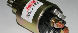
In this article we will talk about what a starter solenoid relay is and understand its design using the VAZ-2114 as an example. In addition, we will consider its malfunctions, as well as possible malfunctions of other elements of the engine starting system that have similar symptoms.
The design of the starting device and where the starter relay is located on the VAZ-2114
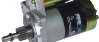
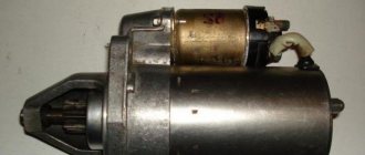
The “fourteenth” starter is a conventional DC electric motor, consisting of:
- housings;
- four-pole armature (rotor);
- Bendix (overrunning clutch);
- solenoid (traction) relay.
The device body is closed with two covers. In the design of an electric motor, it plays the role of a stator. Inside it there is a four-pole armature (shaft with windings), rotating around its horizontal axis. The shaft is supported by two support bearings located in the motor housing.
The Bendix, or overrunning clutch, is a mechanism that engages the armature gear with the crankshaft flywheel ring. It is located at the front of the rotor.
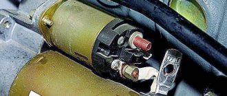
Where is the starter relay located on the VAZ-2114? It is located right on it. Above. In fact, this is not an ordinary, in our understanding, device that closes contacts. It performs two functions at once. It closes the contacts of the armature winding and also drives the bendix and gear.
Purpose of fuses
Starter relay for VAZ 2114: self-diagnosis of the breakdown
What fuses are on the VAZ 2114? The electrical circuit of this car is designed in such a way that in front of all the main electrical units there are chargers located in the fuse box.
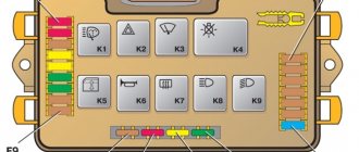
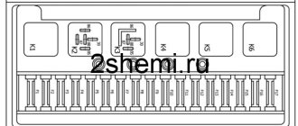
VAZ 2114 fuse diagram
The connection diagram of these protective devices is shown in the figure.
- F1 - rated insert current 10 A - protects the fog lamps located at the rear.
- F2 - with a current of 10 A - these are left and right turn lights, an emergency warning light, a relay-breaker for turn lights and emergency lights.
- F3 - with a current of 7.5 A - protection of light bulbs in the cabin and trunk, trip computer circuits, ignition and brake lights, "Check engine" warning light.
- F4 - with a current of 20 A - protects switches located in the heating circuit of the trunk door glass and heating elements of this glass, “carrying” contacts.
- F5 - with a current of 20 A - protects the horn circuit and its switch, as well as the electric motor of the cooling system fan.
- F6 - with a current of 30 A - this is a circuit of electric windows and their switches with contacts.
- F7 - with a current of 30 A - a protective device for three electrical units - a heater, a windshield washer and a headlight cleaner. In addition, there is also a cigarette lighter, glove compartment lighting and winding for the heating switch for the trunk door glass.
- F8 - with a current of 7.5 A - is protection for the right fog light bulb located in front.
- F9 - with a current of 7.5 A - this is protection for the left fog light bulb located in front.
- F10 - with a current of 7.5 A - protects the indicator lights on the left side, the license plate number, the engine compartment light, the dashboard lights and switches with heating levers, as well as the indicator lights for the size.
- F11 - with a current of 7.5 A - protects the right-side headlight bulbs.
- F12 - with a current of 7.5 A - a protective device for the right low beam headlight bulb.
- F13 - with a current of 7.5 A - a protective device for the left low beam headlight bulb.
- F14 - with a current of 7.5 A - protects the left high beam headlight and the blue high beam warning light.
- F15 - with a current of 7.5 A - protects the right high beam headlight.
- F16 - with a current of 15 A - protects the light bulbs and the turn switch and hazard warning lights, the white reverse light, the power supply of the instrument cluster, the trip computer, the generator winding (at startup), the lights indicating low oil pressure, brake fluid and parking brake, battery discharge.
Operating principle
When the ignition is turned off, the armature, thanks to the spring, is in the extended position. The Bendix gear, however, is not engaged with the flywheel crown. When we turn the ignition key to the second position, voltage is applied to the relay contacts. The magnetic field created by the retractor coil drives the armature. It moves backward, compressing the spring, and closes the contacts through which voltage is supplied to the starter. The retracting winding is turned off at this moment, and the holding winding is turned on.
During movement, the armature moves the fork along the rotor shaft. She, in turn, moves the bendix, bringing the gear into engagement with the flywheel. When we release the ignition key, the voltage on the holding coil stops flowing, and the armature returns to its original position under the influence of the spring. The fork, at the same time, disconnects the Bendix gear and the flywheel crown.
Necessary tool
Starter relay VAZ 2114
Without tools, dismantling and installing a new part cannot be accomplished. The procedure for removing the solenoid relay or starter assembly requires a simple set of wrenches. The following tools will be useful for trouble-free work:
- Socket wrench and open-end wrench 13.
- Phillips and flat head screwdrivers.
- Key for 10.
- New retractor.
A simple set with all types of keys will be useful to any driver, because... No one is immune from sudden breakdowns of VAZ cars. The advantage of the 2114 model is that repairing most components is cheap, and even a novice driver can change the retractor on a VAZ 2114.
Signs of a malfunctioning retractor relay
A faulty traction relay can be identified by the following symptoms:
- when the ignition is turned on, there is no characteristic click accompanying the movement of the device’s armature to the rearmost position (the starter does not turn, the engine does not start);
- a click is heard, but the trigger does not fire;
- The relay is triggered, the starter starts the engine, but does not turn off.
If you turn on the ignition and find that the engine does not start, and one of the listed signs of a faulty starting device is present, try to find the problem yourself. In some cases, the damage may be on the surface, and it will only take a few minutes to fix it.
Checking work
Sometimes, despite more than obvious signs of breakage or wear of the retractor, in reality everything turns out to be wrong. The car may behave similarly with some other malfunctions.
Therefore, in order to figure out whether the relay works or not, and also who is the real culprit for the violation of the functionality of the system, we will conduct several checks.
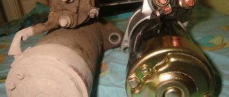
- Check the starter. Turn the ignition key. The starter should begin to turn, and the relay should make a characteristic click. If the starter is not doing its job, replace it. Relyukha has nothing to do with it in this case.
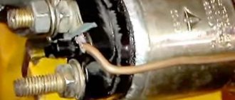
- Check the solenoid relay. To do this, there are two copper bolts on the back cover. Two contacts are attached to them. If the starter starts turning, then your relay has definitely failed and needs to be replaced. In this case, you should not remove the starter, which will allow you to get more accurate test results.
- If you have removed the starter, the check is performed slightly differently : Connect the contact wire of the retractor relay to the positive terminal of the battery;
- The second contact connects the starter ground and the battery charger;
- When the contacts are placed on the relay terminals, the relay should turn on with a characteristic click;
- If the operation is too slow, uncharacteristic, check the condition of the contacts. They often burn out or oxidize.
No clicking of the solenoid relay
The absence of a click may indicate that either there is no voltage supplied to it, or there are problems with the pull-in winding. First of all, we check the wiring. To do this, visually inspect the positive wire going to the relay from the battery, and then the thin wire from the ignition switch. If possible, check the voltage level with a voltmeter (multimeter), connecting its positive probe to the terminal on the relay from which the wire goes to the battery, and the negative probe to ground. The device should show battery voltage. If this indicator is lower, you need to look for a problem in the wiring.
If there is voltage to the relay, try to start the engine directly, without the ignition switch. To do this, disconnect the wire coming from it and use a screwdriver to close the relay contacts (output to the battery and output to the starter). It worked? Deal with the contact group of the ignition switch.
Preliminary safety notes
- Voltage above 36 volts is considered dangerous to humans. Electric shock of 0.1 ampere is fatal. The situation is aggravated by high humidity and metal flooring.
- The starter is a DC electric motor capable of delivering 260 amps at maximum load.
- Interfering with bare hands or metal tools into the current circuits of a switched-on unit is dangerous to health. Dismantling, repairs, and installation must be performed with the battery power turned off.
- Testing windings for interturn short circuit and insulation breakdown to ground is performed with a megger. The generator of the measuring device produces voltage up to 2500 volts. It is prohibited to touch the contacts during the verification process.
- Electric motor equipment requires care and experience. Printed and electronic publications are not deprived of the right to errors or typos. An incorrect wrench size will quickly become apparent. A play on Russian words will sound, untranslatable into foreign languages. Things will go further. The inaccuracy of the diagram is hardly noticeable.
- At the first symptoms of uncertainty or lack of knowledge, you should contact a professional auto electrician. The safety of car wiring and on-board electronics is valued above personal ambitions.
There is a click, but the starter does not turn
If you clearly hear the relay click when you turn on the ignition, the problem is most likely in the starter itself. Perhaps the brushes are worn out, or there is a break in one of the windings. In any case, further diagnostics without dismantling the device is impossible. If a break in the windings is detected, you can try to restore the starting device by entrusting it to winding winding specialists. If things are generally bad with it, it is better to buy a new starter 2114. The price for it varies between 3700-5000 rubles.
Electrical diagram of VAZ 2115
Such models are marked with the numbers F2 10A Direction indicators, relay-breaker for direction indicators and hazard warning lights in hazard warning mode. Then release the pressure, turn off the power to the fuel pump and turn on the ignition. In some cases, the problem in the operation of certain devices is solved by reconnecting the plug if it is a question of poor contact of the device with the electrical network. Lift the pump assembly and pull out the electrically powered fuel pump. It has an anti-theft device. In this case, the blocks “12” are connected to the washer pump, and the wires connected to the pumps “13” and “14” are connected to the corresponding solenoid valves.
As a result of the change in the circuit, changes were made to the design of some electrical circuits. Table 7. Distributive fuel injection systems are controlled electronically.
Using a screwdriver, unscrew the 2 screws that fit the fuel lock and pull it out. Learning to read a car's electrical diagram. Part 1. Auto electrics.
How to replace the VAZ-2114 starter solenoid relay
Now let’s move on to the process of dismantling and replacing the “fourteenth” traction relay. Let us immediately note that for this it is better to remove the starter assembly. This way it will be possible to simultaneously check the condition of its brush assembly and bearings. So, the process of replacing the relay is as follows:
- Remove the negative terminal from the battery.
- Disconnect the wires from the relay terminals and from the terminal of the starter brush assembly.
- Unscrew the bolts securing the starter to the clutch housing. We remove it from its seat.
- Unscrew the coupling bolts securing the relay.
- Disconnect the relay from the starter and install a new one in its place.
- We carry out installation in reverse order.
Engine control circuit (January 5.1, Bosch M1.5.4N)
- Fragment of the mounting block;
- Electric engine cooling fan;
- Automotive anti-theft system status indicator;
- Automotive anti-theft system control unit;
- Coolant temperature sensor;
- Air flow sensor;
- Throttle pipe;
- Block connected to the throttle position sensor;
- Block attached to the idle speed control;
- Controller;
- A block connected to the air conditioner wiring harness;
- Oxygen sensor;
- Knock sensor;
- Crankshaft position sensor;
- Speed sensor;
- Adsorber;
- Accumulator battery;
- Main relay;
- A block connected to the anti-lock brake system wiring harness;
- Diagnostic block;
- Main relay circuit protection fuse;
- Controller protection fuse;
- Fuse for protecting the electric fuel pump and its relay;
- Relay for turning on the electric fuel pump;
- Electric fan switch relay;
- A block connected to the instrument panel wiring harness;
- A block connected to the instrument panel wiring harness;
- Ignition module;
- Electric fuel pump with fuel level sensor;
- Spark plug;
- Injectors;
- F — Front harness wire going to the “B+” terminal of the generator;
- G - Front wiring harness wires.
The order of conditional numbering of plugs in blocks:
- A - Controller;
- B — Control unit of the automobile anti-theft system;
- B — Indicator of the status of the automobile anti-theft system;
- G - Pads 26;
- D - Throttle pipe;
- E - Air flow sensor;
- F - Electric fuel pump and oxygen sensor;
- 3 — Speed sensor;
- And - Ignition module.
Purpose of plugs in block 26:
- To the low-voltage tachometer input in the instrument cluster;
- —
- To the engine management system control lamp in the instrument cluster (from the controller);
- To the dome light switch located on the driver's door pillar;
- To the engine control system control lamp in the instrument cluster (+ power supply);
- To the trip computer (fuel consumption signal);
- To the instrument cluster (vehicle speed signal);
- To terminal “15” of the ignition switch (plug 4 of the switch block).
Other relay
We figured out where the starter relay is located on the VAZ-2114 and how to replace it. But in the engine starting system there is another part with the same name. Yes, yes, it is also called the “starter relay”. Only extra. And its function is completely different. An additional starter relay serves to ensure the safety of the entire starting mechanism. Without it, the brushes and armature windings would burn almost every time it was started.
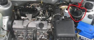
You will ask again, where is the starter relay located on the VAZ-2114? On the first models of the “fourteenth” it was located in the engine compartment at the top on the partition separating the engine compartment and the interior. On the new VAZ-2114 it is not there. And some “experts” foam at the mouth and prove that cars of the Samara-2 family do not have it at all.
In fact, there is an additional relay, but it is located under the steering column. Just remove the bottom part of the plastic casing and you will immediately see it. This is a regular four-pin relay labeled 98.3777-10 that protects the starter circuit. If you have problems starting the power unit, do not be lazy to check it too.
Dismantling and replacement
To make it more convenient to replace the relay, it is recommended not to be lazy and still remove the starter itself. This will allow you to simultaneously check the condition of the starter while replacing the relay.
The removal procedure described below concerns an assembled relay, which has the ability to replace individual structural elements.
- Disconnect the negative terminal from the battery.
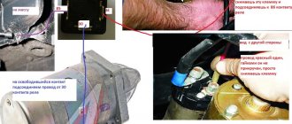
- Disconnect the red terminal from the relay. This is a red wire.
- Using an 8 mm wrench, unscrew the nut securing the brush assembly. You will find it behind the relay.
- Remove the contact that this nut held in place.
- Unscrew the fastening of the solenoid relay to ground. We are talking about coupling bolts.
- Next, you need to dismantle the power wire, after which the relay itself is pulled out.
- The fastening nuts are unscrewed from the end part, which allows you to remove the upper part of the relay.
- It is advisable to immediately replace the relay core with a new one.
- Install a new relay.
- Proceeding strictly in reverse order, reassemble the assembly, which will allow you to complete the replacement of the unit.
- When separating the relay into its two component parts, be sure to ensure that the core does not slip out and the spring does not jump out.
But there is one more very important point. Even if all the facts indicate that the starter or retractor relay is not working, another unit - the ignition switch - may still be the cause of ignition problems. Take the time to check its serviceability before buying new parts.
Fuse box
The VAZ 2114 car has a total of two mounting blocks.
The first and main one is installed in the engine compartment above the windshield on the left. Relays and fuses are located there. Actually, largely because of this, it is often called a fuse block rather than a mounting block.
The unit cover is held in place by special plastic clips, which makes it easy to snap and remove. On the inside of the cover there is a fuse diagram, the rated current of each individual charger.
Under no circumstances should you install a charger into the mounting block whose current strength exceeds the rated values provided for in the circuit. This may lead to electrical equipment failure.
In the image above you can see that there are tweezers in the corner of the block. It is specifically included in the design, since it is used to dismantle and install new fuses.
In total, the power supply includes 17 active fuses (F1-F16) and four more backup fuses - F17-F20.
Also for the VAZ 2114 there is a second block with fuses. It is located inside the cabin under the glove compartment and shelf. This PSU includes the following fuses:
- For fuel pump. Rated current -15A;
- For fan relay, speed sensor, mass air flow sensor and oxygen sensor. All of them have a rated current of 7.5A;
- To protect the ignition unit and electronic engine control unit. Their normal current is also 7.5A.
Purpose of the memory
In order to quickly resolve issues with failed fuses, VAZ 2114 owners should figure out which charger is intended for what. This will make it much easier for you to navigate the notations. Use a special table.
Protection for the lamp and turn switch, hazard lights, white reverse lamp, instrument unit power supply, trip computer, alternator winding, low oil pressure warning light, parking brake, brake fluid and low battery
If the engine becomes unstable, electrical problems arise, light bulbs burn out, or electrical appliances stop working, the first step is to check the effectiveness and integrity of the fuses.
To do this, the following activities are performed.
- Determine the location of fuses that may fail. You already know the diagram, the designations are also familiar to you. Therefore, it remains to be understood that the charger should be looked for under the hood or in the block inside the cabin.
- Be sure to turn off the power to the car. To do this, simply remove the negative terminal from the battery.
- Remove the plastic clips that hold the plastic cover of the mounting block in place. This is how you can easily remove the block.
- Remove the tweezers from the mount, which are located directly inside the mounting block next to the fuses and relays.
- Use tweezers to grab the device that you suspect is broken and pull it out.
- Now you really need to make sure that the fuse is blown and not working. To do this, visually inspect the fusible element. If it comes off or is deformed, it means that the protection has worked, and therefore the fuse will have to be replaced.
- But it is not always possible to detect a memory failure using the visual method. In this case, you will have to use a tester.
- Having reached the truth, that is, having determined that the protective device has failed, it will be enough to replace it with a new one.
Today, a new fuse, depending on its type, costs around 150-300 rubles. If you need to completely replace the entire fuse box, then you will have to spend about 2,000 rubles.
Safety regulations
Now a few more safety rules:
- Under no circumstances insert homemade devices and jumpers in place of broken chargers;
- Never install fuses whose rated current exceeds the values indicated on the housing cover. This may result in a short circuit and fire in the vehicle;
- Do not use metal screwdrivers or other metal tools when working with the mounting block. This even applies if the car is de-energized, that is, the battery is disconnected.