In any modern automobile engine, continuous fault diagnosis and adjustment of adjustment data are carried out using electronic systems. All VAZ injection engines, including the eight-valve engine on the 2110, are equipped with an engine management system. Each of the important indicators is monitored using a mass of sensors, and the knock sensor is one of them.
Knock sensor VAZ 2110 - purpose of the device
Detonation is a rather unpleasant phenomenon caused by spontaneous uncontrolled combustion of fuel in the combustion chamber.
It can occur due to many reasons - low-quality fuel or inappropriate compression ratio, incorrect operation of spark plugs.
But basically, detonation occurs due to an incorrectly set ignition timing.
A knock sensor will help identify the occurrence of undesirable phenomena in engine operation.
It is in this case that the knock sensor will help to determine the occurrence of an undesirable process at the very initial stage and transmit information about the beginning of detonation to the electronic engine control unit. The ECU, in turn, will adjust the ignition timing automatically to counteract the incipient detonation.
Pros of a working sensor
A working knock sensor will completely relieve the engine from overheating, ensure fuel savings and optimal power and traction.
Operating principle and location
Ignition too early can result in engine overheating, detonation, loss of power and excessive fuel consumption. Too late - the same, but at the same time starting the engine, especially a cold one, is quite difficult.
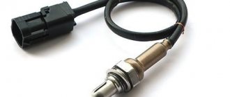
The piezoelectric knock sensor converts vibrations and noise in the cylinder head into an electrical impulse and transmits this data to the electronic control unit - the greater the one-time pressure on the sensor (micro-explosion, increased vibration), the stronger the signal from it.
The VAZ-2110 is equipped with two types of knock sensors.
There are two types of knock sensors:
- resonant type;
- broadband sensor.
Knock sensor diagram.
The first type of sensor is configured to oscillate at a certain frequency, it is more accurate and is used on cars manufactured after 2002–2003 . A wideband sensor perceives the entire spectrum of frequencies and its readings are approximate, and the range of the transmitted signal is quite wide.
The two types of sensors are not interchangeable, and before checking and installing a new one, you must know exactly what type of sensor is installed on the engine.
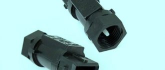
The knock sensor on the VAZ-2112 is located on the front of the engine, next to the oil dipstick.
The sensor is screwed into the cylinder block on the left side under the spark plugs; its replacement and diagnostics take a few minutes.
Preparing for replacement
In order for the procedure for replacing the controller on the tenth VAZ model to proceed correctly and to obtain the expected result, namely the normal functioning of the speedometer, you should be properly prepared for this process.
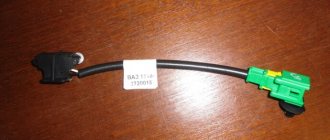
Firstly, on a VAZ 2110, replacing the DS means purchasing a new controller
When purchasing a new regulator, you need to pay attention to the fact that each connector located in the block design has certain symbols. It should contain the symbols “-”, “A” and “+”, not numbers
In principle, in this case there is not much difference between these options; when connecting the connector you will have fewer problems with pinout. If you have never encountered a process like this, this pinout will allow you to complete it correctly.
Controller connector pinout
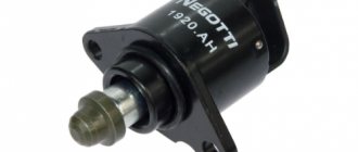
One more, no less important nuance. You need to buy a device that is equipped with a metal rod. This rod will last at least six months, which cannot be said about regulators with plastic rods. In addition, when purchasing, you must check whether the rod rotates or not. It should not rotate, there should be no play on this element, and it should also be equipped with a washer.
Symptoms of a problem
Before replacing the knock sensor, make sure that it is not working. Most often, sensor failure is due to an open circuit. This is expressed primarily in engine overheating and loss of power. In addition, the Check Engine warning light may come on when the load on the engine increases , the engine may stall and operate unstably regardless of speed.
When the knock sensor fails, the Check Engine light comes on.
Search
The easiest way to start troubleshooting is by reading the error codes. Depending on the type of error, we will take appropriate measures:
- code 0325 indicates that there is no contact in the sensor circuit, most likely the sensor connectors have oxidized, and in this case it is enough to ring its circuit and clean the contacts;
- with the same error, it is possible that the timing belt has slipped one tooth; it does not hurt to check the correct installation of the belt according to the marks;
- 0326, 0327 — low signal from the knock sensor, first let’s check the contacts and the tightening torque of the device fixing nut, it needs to be tightened with a force of 10–23 Nm, only then the sensor will work correctly;
- 0328 - the signal from the sensor exceeds the norm, this error basically indicates a malfunction of the sensor.
Depending on the manufacturer, the price of the sensor can be either 1200 rubles (Bosch, article number 2112–3855010 or 0 261 231 046 ), or 200–300 rubles for a domestically produced device. Their articles are 18.3855–01/18.3855 , 18.3855–01 and 2112–3855010 .
Stable operation of the 8-valve injector of the VAZ 2110 is ensured by a number of sensors. Each of them performs specific functions. Therefore, the failure of one regulator prevents the transfer of information to the electronic control unit. As a result, the ECU does not send signals to the power unit or transmits incorrect information.
Today, no one doubts that an injection engine demonstrates maximum efficiency and efficiency compared to a carburetor unit. Electronic fuel injection into the cylinders is one of the functions of the injector and provides it with a number of advantages.
Stable system operation, increased power and reliability are only possible if the electronics are functioning properly.
The functionality of the system is directly related to the huge number of sensors, which are the topic of this article, in particular:
- crankshaft sensor;
- speed;
- DTZHO;
- air regulator;
- turning on the fan;
- TPDZ;
- detonation.
Let us dwell in more detail on the listed, as well as some other regulators.
Repair and replacement
We carry out dismantling according to the following scheme:
- We de-energize the car by removing the “-” connector from the battery;
- We disconnect the wire connector from the sensor and remember what their pinout is;
- We unscrew the sensor itself by hand. If this doesn’t work, use key 21 or 22 (there may be design differences);
- At the same time, we check how the drive feels. After removing the sensor, you need to unscrew the nut with which the drive is attached to the gearbox. You need to remove it very carefully, since if you drop the rod into the gearbox, you will have to disassemble it too. The new drive has a rubber ring, which is lubricated with transmission oil before installation.
We install new devices in the reverse order. Again, the pinout of the wires is of particular importance.
Inside the block we look at how the pinout is marked. And using a multimeter with the ignition on, we determine which connector goes to which wire.
If the multimeter shows “minus”, and you connected this wire to the plus connector, then you urgently need to change the polarity. In this regard, it is better to take the block that we recommend.
But if there isn’t one, you can use the regular one. In this case, the pinout is as follows: 1 – “+”, 2 – signal output, 3 – “-”.
The drive is checked, as well as the operation in general while the car is moving, or with the front wheels hanging.
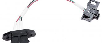
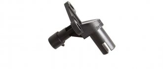
Speed sensor
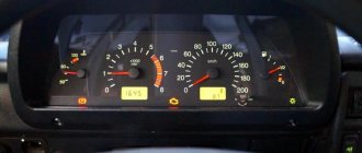
The device is located on the speedometer output shaft. If a malfunction occurs, the vehicle may not idle smoothly. The design is simple and reliable. The operating principle is based on the Hall effect. There were two types of meters installed on the ten - with a square and a round block.
When the speedometer needle jumps, it is recommended to check the device in question, since failure can affect the speed performance of the vehicle.
DTZO: temperature indicator
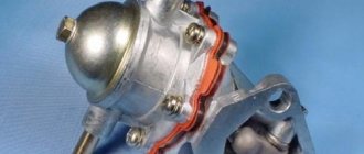
The regulator screws directly into the cooling system pipe. Located between the filter housing and the power unit. The task of the coolant sensor is as follows:
- when starting a cold engine – informing the system about the supply of an enriched mixture;
- if it overheats, turn on the fan to cool the radiator.
If we talk about carburetor engines, then one of the listed functions was performed by the choke. The measuring element (DTZO) plays an important role for the stable operation of the power unit. It is characterized by the following problems:
- violation of contacts;
- high probability of failure if the fan starts when the engine is cold;
- difficulty starting a hot engine;
- increased fuel consumption if the indicator fails.
Poor engine start of VAZ 2110, 2111, 2112 and burnout in the power key ECU gb10nb37lz
One of the reasons for poor engine starting is the burnout of the power key gb10nb37lz in the ECU. But for some reason, many car owners immediately think that their Crankshaft Position Sensor has failed, I once had this problem. But this was also due to the fact that the wire from the sensor lay on ground and when the engine heated up, the braid melted and a short circuit occurred.
And so, our ignition diagram:
The ignition diagram of the VAZ-2110 injection engine shows the following elements -
1 – battery 2 – ignition switch 3 – ignition relay 4 – spark plugs 5 – ignition module 6 – controller 7 – crankshaft position sensor 8 – master disk A – matching device
When the car does not start, most people immediately blame the crankshaft position sensor. Changing it they realize that it didn’t help. When checking the block, the wire does not give any result. The next steps are to install a new module, or the ECU doesn’t do anything either. The car still won't start.
Everything is simple: the crankshaft sensor just has its own resistance, like the ignition module, by ringing it you can understand whether they are in good condition. Also don’t forget to check the fuse and main relay. Next, we check the spark plugs and armor wires, whether the retractor on the starter works (just put your hand on it, and if it doesn’t hit when starting up, then it’s working). During this check, you can understand what is wrong.
Checking the Crankshaft Position Sensor:
1. Connect a multimeter to the sensor terminals (in voltmeter mode with a measurement limit of up to 200 mV).
2. We quickly move the screwdriver blade close to the end of the sensor, while we observe voltage surges on the voltmeter.
Conclusion: The sensor is working.
Checking the DPKV circuit: With the ignition off, disconnect the engine management system wiring harness block from the crankshaft position sensor. We connect the tester probes to terminal “B” of the wiring harness block and engine ground.
With the ignition on and the crankshaft stationary, the tester should record a voltage of about 2.5 V.
A similar voltage should be between terminal “A” of the wiring harness block and engine ground. If the voltage values do not correspond to the norm, check the serviceability of the circuits (open and short to ground) between terminal “B” of the wiring harness block and terminal “34” of the controller, as well as between terminal “A” of the block and terminal “15” of the controller. If the voltage values do not match and the circuits are working, the controller is faulty.
Checking the ignition module:
1. 1a-signal coming from VT3 transistor to the ECU (power switch gb10nb37lz) 2. 12 volts after ignition 3. 1b-signal coming from VT1 transistor to the ECU (power switch gb10nb37lz)
To check the resistance of the windings, you need to ring the right and middle contacts on the ignition module alternately. Both left and middle. If the module is working properly: the resistance of each winding should be around 0.8 Ohm.
We measure the resistance of windings 1-4, the winding is OK - resistance is 0.8 Ohm.
We measure the resistance of winding 2-3, the winding is PROBITED (short circuit) - resistance is 0.1 Ohm.
Conclusion: The module is faulty and needs to be replaced. Perhaps the power switch in the ECU could have burned out.
I think anyone can check the Armor of wires, and the same with spark plugs, I don’t think it’s worth describing this.
And so, we have on our hands a failed Ignition Module (The ignition module does not always clearly visually fail; it may have hidden damage. Since the module is a kind of transformer, it may have either a broken winding or a short circuit. What will disrupt the operation of the ignition system. And will cause a higher current, which will lead to the burning of the power switch.)
Interconnection diagram between the Module and the ECU:
First, let's check whether there is a control signal at the ignition module connector from the ECU. How can this be checked?
To check whether a pulse goes from the ECU to the ignition module, you can use a regular LED with a resistor (500...700 Ohm). We connect in the following order:
First, we connect the cathode of the LED to pin 1b of the ignition module connector, and connect the anode (+) of the LED to pin 15 (+12 after ignition). After connecting the LED, simply turn it with the starter. The LED should start flashing. The blinking of the LED informs us that the ECU is sending an impulse to pin 1b of the connector. We connect to pin 1a in the same way and repeat the verification procedure. If there are no flashes when you connect the LED, it means there is an open circuit somewhere in the wiring. If the LED is constantly on, this means that there is a short circuit, or the power switch (transistor VT1, VT3) has burned out and is constantly shorting to ground.
Mass air flow sensor: air regulator
The tens electronic system needs information about the amount of air required. This is necessary to create the optimal volume of the warm-air mixture.
Considering the sensors of the VAZ 2110 injector 8 valves , it should be noted that the mass air flow sensor is the most sensitive of all devices.
A small amount of moisture or dust can cause damage. This must be taken into account during the car repair process. So, the sensor determines the volume of air before entering the system. The disadvantages of the device are:
- sensitivity to moisture and dust;
- malfunctions during operation of the power unit at idle speed;
- increased fuel consumption;
- difficulty starting the engine;
- at increased speeds and significant loads, the power unit may stop abruptly.
All of the above reasons are due to the fact that a mixture that is too lean (or rich) gets into the cylinders. The operating principle of the device in question is quite simple. There are several heating elements inside the structure, which “lose” temperature as air passes through. The more electricity used to heat these components, the more air enters the system.
Thus, the change in electrical power is directly related to air flow. The information is transmitted to the system, which turns on the appropriate modes and controls air flow.
Fan sensor
This tool is necessary for measuring temperature and then turning on a fan designed to cool the engine. Unlike other devices, it is reliable and has a long service life. The sensor is filled with a solid substance that expands as the temperature increases. By purchasing high-quality products, owners of the VAZ-2110 model will be able to forget about the need for replacement for a long time.
The task of the device in question is reduced to transmitting a signal to the computer as a result of pressing the gas pedal. Thus, the amount of fuel injected increases. The design of the regulator is quite reliable. Failure is indicated by jerking when pressing the accelerator pedal. Also, sometimes “failures” occur. A regular tester is used for testing.
If the damper is closed, the voltage is about 0.5 Volts. When you press the pedal as hard as possible, the voltage increases to 4 volts.
Knock sensor
The device is mounted on the cylinder block. Its function is reduced to transmitting information about detonation to the electronic control unit. As a result of increased detonation, the ECU (in accordance with the software) changes the operation of the power unit. Dozens of recent series have piezoceramic devices installed. Functionality testing is performed using a tester. To do this, you need to connect the meter to the contacts of the device and lightly knock. The measuring device should record voltage drops, which indicates proper operation.
There are other sensors, such as valve timing and a lambda probe, that can be installed on cars with 8 and 16 valves. To study the features of each device, it is recommended to use the instruction manual for the VAZ 2110 car.
Any modern car is equipped with many different sensors that allow the driver to know about the condition and performance of certain components. And the VAZ 2110 car is no exception; in this article we will talk about what sensors are used in it and what their location is.
As you know, the VAZ 2110 injector with 8 or 16 valves is significantly superior to the carburetor version in many ways. At least because in this case the supply of gasoline, as well as the combustible mixture, is regulated by electronics. Accordingly, the use of electronics implies the use of many different regulators and controllers. Their breakdown can lead to certain consequences, so the car owner should always know what certain regulators are responsible for. Below we consider almost all VAZ sensors that are in the top ten.
The power unit of the "tens" is controlled using the ECM - an electronic system. This system must always know how much air needs to be supplied for a certain volume of gasoline. These two parameters are closely related to each other, since with their help a combustible mixture with the required density is formed in the engine power unit. After the system determines the required volume of air, it begins to select the appropriate amount of gasoline. As for the regulator, it is responsible for the suction volumes.
Throttle controller
Designed for dosing fuel in cylinders. When you press the gas pedal on an injection engine, only the air damper mechanically opens. The amount of gasoline to create the working mixture changes according to a command from the ECU. This is what the throttle position sensor (TPS) is designed for.
The controller is a variable resistance, essentially the same as the volume control on a car radio. Only the voltage supplied to the control unit changes here. Roughly speaking, TPS converts the force of pressing the gas pedal into a certain electrical signal. It goes to the ECU, in which the voltage/fuel quantity relationship is hard-wired with great precision.
The signal amplitude varies from 0.7 to 4 V (with the damper fully open). The incoming gasoline also changes linearly. The TPS is installed directly on the throttle assembly.
Coolant temperature sensor
On the VAZ 2110, sensors can be used for different purposes, but most of them are mounted in the engine compartment. On an 8 or 16 valve engine, the fan sensor is a device designed to activate the fan. We are talking directly about a fan designed to cool a hot engine.
The controller turns on automatically when the power unit reaches a certain temperature. But it can also turn on when the engine is off. At first, this fact may be alarming for many owners of the “ten”, but there is nothing wrong with it, so there is no need to worry.
It is necessary to highlight the advantages of this controller:
- As practice has shown, the fan sensor is one of the most reliable vehicle devices, since its design is based on a solid filler. When the ambient temperature increases, this filler begins to expand.
- The design of this device also includes a special spring-loaded lever. Thanks to this component, no defects occur during the operation of the regulator.
- The device prevents sparks from appearing, which is especially important for ensuring vehicle safety.
- In fact, this type of regulator itself is reliable. If you buy a high-quality device, then in the future you will notice that it will function for quite a long time; you can forget about the need to replace it for the next few years.
Fan controller
Serves to force cooling on. The VAZ-2110 fan sensor was installed only on the first “ten” models equipped with a carburetor engine. Structurally, it is a sealed brass cylinder, inside of which there are bimetal contacts. When heated, they bend and close the electrical circuit, the fan turns on. True, its high current consumption (about 15 amperes) does not allow it to be powered directly, through bimetallic contacts. For this purpose, there is a special relay in the circuit.
The main disadvantage of the controller is its low reliability. The sensor often stops working, which can lead to engine overheating. Its location at the bottom of the radiator makes replacement quite labor-intensive. The coolant will need to be completely drained.
Crankshaft regulator
Depending on the type of car, on a 16- and 8-valve engine, the location of all controllers may be different. However, all of these devices combine into one functioning system, and the crankshaft adjuster is no exception. Thanks to this controller, the electronic engine management system of the “tens” can independently determine at what point to supply gasoline and a spark through the spark plugs in order to ignite the combustible mixture. In fact, the design of the device is a magnet, as well as a coil of thin wire.
The crankshaft sensor has certain advantages:
- As practice shows, at “tens” this regulator can work for quite a long time. Its service life does not decrease even as a result of using the vehicle’s power unit under increased loads.
- The crankshaft adjuster works in conjunction with the crankshaft pulley.
- If the device fails, the engine may not be able to start. Or, if the regulator breaks down, the speed parameters will be reduced to 3.5 thousand per minute.
This controller is installed on the oil pump, actually at the very top of the shaft teeth. Or rather, one millimeter from the cloves. You can learn more about how to replace this controller yourself from the video below (the author of the video is the channel In Sandro’s Garage).
DIY repair and replacement
If you decide to replace the device yourself, familiarize yourself with the removal and replacement procedure.
The controller is dismantled as follows:
First you need to de-energize the vehicle's on-board network; to do this, disconnect the negative cable from the battery. Next, disconnect the connector with wiring from the controller itself. At this stage, it is important to remember what pinout these elements have. The controller itself can be unscrewed by hand. If you can’t do this on your own, try using a 21 or 22 wrench. In this case, the regulator may have certain differences in design. Also immediately check how well the drive functions. After the regulator is removed, it is necessary to unscrew the nut that secures the drive to the gearbox
The dismantling procedure must be done very carefully, because if you accidentally drop the rod into the transmission, the box will need to be removed and disassembled. As for the new drive, it is equipped with a rubber seal
Before installation, it must be lubricated with transmission fluid. Below is a video that will allow you to more clearly understand the procedure for replacing the controller (the author of the video is Auto News).
All new components must be installed in reverse order. Again, in this case the wiring pinout plays a big role. Inside the block itself you can see how the pinout is indicated. Using a tester with the ignition activated, it is necessary to determine which connector the drive should be connected to.
If the multimeter shows “-” and the drive was connected to the positive connector, this indicates that the polarity needs to be changed. Next, the drive is diagnosed, and you should also check the operation of the speedometer while driving or with the front of the vehicle raised (so that the wheels are suspended).
If you doubt that you can carry out the entire procedure yourself and change the controller correctly, we advise you to seek help from specialists. In principle, this process is not particularly complicated, so the cost of the replacement service will not be particularly high. For installation, it is better to use a higher-quality regulator so that in the future you do not face the need to repair and replace it.
Coolant temperature indicator
Antifreeze or coolant is used to cool the engine. To ensure proper operation of the power unit, the coolant also has its own controller. In its functionality, this regulator is vaguely reminiscent of the choke that is equipped with 8- and 16-valve carburetor engines of the “ten” and other vehicles. The sensor itself is designed to monitor the temperature of the consumable.
Installing a new antifreeze sensor
In fact, this device also provides fuel regulation. If the power unit is running cold and has not yet warmed up, it will receive more gasoline for normal operation. Readings about the coolant temperature are displayed on the control panel in the vehicle interior. In accordance with these indicators, the driver will always be able to find out about the overheating of the unit by the way the sensor arrow on the dashboard begins to move into the red zone.
The antifreeze temperature sensor periodically fails; it is characterized by the following malfunctions:
- Loss of electrical contact inside the controller, resulting in its inoperability.
- The device is installed in such a way that it may be exposed to moving elements, particularly the accelerator pedal cable. It would be even more correct to say that the cable does not act on the sensor itself, but on its wires, which in fact can lose insulation as a result of long-term use.
- Often the regulator breaks down if the ventilation device starts to function on an engine that is not warmed up.
- If the motor is overheated, it may be difficult to start.
- If the fuel temperature controller fails, it can lead to increased gas mileage. If you encounter one of these problems, then to ensure normal operation of the car engine, you need to replace the controller. Detailed replacement instructions are presented in the video below (author - REPAIR VAZ 2110, 2111, 2112).
Gasoline level indicator
The fuel sensor of the VAZ-2110, like any other car, is a rheostat made of nichrome wire. Its moving contact is mechanically connected to a float, which is located in the tank on the surface of the gasoline. The fuel level changes, and along with it the resistance of the rheostat, which is recorded by the device on the panel.
In addition, there is an indication of the reserve amount of gasoline. It works thanks to the same float. In a certain position, it closes the contacts, which causes the warning lamp to turn on. The fuel gauge cannot be called an accurate and reliable device. However, these are the disadvantages of all mechanical sensors. The main malfunctions are associated with damage to the nichrome wire, which simply wears out due to the constant movement of the “runner”.
The sensor is naturally installed in the tank, and replacing it does not present any difficulties. True, you will have to remove the fuel pump and partially drain the fuel if the car is “filled to capacity.”
Speed sensor
8- and 16-valve “tens” are also equipped with a speed sensor. Thanks to this device, the electronic engine control system receives information about how fast the vehicle is moving. The sensor itself is installed on the vehicle's gearbox. As practice has shown, on VAZ 2110 cars this controller is characterized by fairly high reliability and a long service life.
But domestic developers could not do everything perfectly, so this device is characterized by several malfunctions:
- If a component fails or does not work correctly, then when idling, the power unit may turn off on its own.
- A failed regulator can partially affect the speed characteristics of the vehicle. Of course, if the device breaks down completely, the driver will not be able to know how fast it is moving.
Two speed controllers
How to independently diagnose the unit?
At first glance, it may seem that diagnosing an ECU is a difficult task that not everyone can handle. Indeed, checking your block is not so easy, but having theoretical knowledge, it is quite possible to apply it in practice.
Required tools and equipment
To check the functionality of the module yourself, you will need to perform a number of steps to connect to the ECU.
To perform the test you will need the following devices and elements:
- Oscilloscope. It’s clear that not every car enthusiast has such a device, so if you don’t have one, you can use a computer with the necessary diagnostic software pre-installed on it.
- Cable for connecting to the device. You need to select an adapter that supports the KWP2000 protocol.
- Software. Finding diagnostic software today is not a problem. To do this, just monitor the network and find a program that is suitable for your vehicle. The program is selected taking into account the car, since different control units are installed on different cars.
Algorithm of actions
The diagnostic procedure for the electronic control system is discussed below using the Bosch M 7.9.7 module as an example. This control unit model is one of the most common not only in domestic VAZ cars, but also in foreign-made cars. It should also be noted that the verification process is described using the example of using the KWP-D software.
So, how to check the ECU at home:
First of all, the adapter used must be connected to a computer or laptop, as well as the ECM itself. To do this, connect one end of the cable to the output on the unit, and the other to the USB output on the computer. Next, you need to turn the key in the car's ignition, but you do not need to start the engine. By turning on the ignition, you can launch the diagnostic utility on your computer. After completing these steps, a window with a message should pop up on the computer screen, which confirms the successful start of diagnosing malfunctions in the controller. If for some reason the message does not appear, you need to make sure that the computer successfully connected to the controller
Check the quality of the connection and connection of the cable to the unit and laptop. Then a table should be displayed on the laptop display, which will indicate the main technical characteristics and operating parameters of the vehicle. At the next stage, you need to pay attention to the DTC section (it may be called differently in different programs). This section will present all the faults with which the power unit operates
All errors will be displayed on the screen in the form of encrypted combinations of letters and numbers. To decipher them, you need to go to another section, which is usually called Codes, or use the technical documentation for your car. If there are no errors in this section, then you now don’t have to worry, since the vehicle’s engine is working perfectly (the author of the video about ECU repair at home is the AUTO REZ channel).
But this verification option is most relevant if the computer sees the block. If you have problems connecting to it, then you will need an electrical diagram of the device, as well as a multimeter. The tester or multimeter itself can be purchased at any specialty store, and the electrical circuit diagram of the ECM should be in the service manual. The diagram itself needs to be studied most carefully; this will be required for verification.
In the event that the ECM points to a specific block, and does not show erratic data, then in accordance with the diagram it needs to be found and called. If there is no accurate information, then the only way out is to diagnose the entire system; as we said above, breakdowns are considered one of the main faults.
After the breakdown is found, it is necessary to check the resistance and determine exactly where the cable is fixed. You will need to solder the corresponding new wire parallel to the old one; if the reason lies in the breakdown, then these actions will eliminate the problem. In all other cases, only qualified specialists can solve the problem.
Phase sensor
This sensor is not installed on 8-valve engines; it is present only on 16-valve versions of the “ten”. The main purpose of the controller is to provide the necessary data to the power unit control system. In accordance with these data, the system determines at what point in time and where to inject fuel, into which specific cylinder. Every owner of a VAZ 2110 should know where this device is located. If you open the engine compartment of the car, you will see that the regulator is located on the right side of the neck for filling the engine fluid.
In principle, if the regulator breaks, nothing bad will happen if you look at it from the point of view of the integrity of the vehicle. But failure of the controller will in any case provoke an increase in gasoline consumption. This is due to the fact that the electronic control system of the internal combustion engine will independently switch the gas distribution mechanism to standby mode. Accordingly, gasoline will begin to be supplied to all cylinders of the engine at once. And at first, the driver may not even know about it until he diagnoses the regulator or measures fuel consumption.
New phase sensor for VAZ 2110
Naturally, such a model of the domestic automobile industry as the “ten” is not the most modern and advanced car in terms of electronics. However, machines of this model are equipped with a wide variety of regulators and controllers. In this article, we did not talk about all the devices, but only about the most basic ones that every motorist should know about. You can find more detailed information in other articles on our website or in the service book for your car.
Where is the VAZ ECU located and the interchangeability of control units
First of all, to determine the type of control unit, you need to find its installation location in the car. To do this, you should study the manual. As an example, let's look at the VAZ 2108 - 2115. On these cars, the ECU is located in the passenger compartment, on the front right, slightly below the glove compartment.
By the way, this information is also useful for computer diagnostics, since you need to know where you can connect to the diagnostic connector installed in various places on a particular model.
Diagnostic connectors VAZ 2108 - 21099 with a low panel are located near the ECU, under the glove compartment. Models VAZ 2108 - 21099 with a high panel, as well as 2113 - 2115, have a connector inside the center console. The VAZ 2108 - 2115 version with the so-called Europanel has a connector on the panel, and it is located closer to the passenger door.
- As for the units themselves, VAZ 2108 - 2115 of different years of production have different ECU models. For example, the most popular ECU January 4 was installed on early models of injection engines with central injection into the intake manifold.
Version January 5 - 6 are ECUs with distributed injection, but without oxygen sensor support. The January 7 control unit has appeared on cars since 2007, supports all sensors, and effectively controls the engine.
Let us also add that in addition to January, different generations of GM units were actively used at VAZ, being an analogy of January 4 - 7. The same can be said about Bosch or Itelma ECUs. Taking into account all the features, interchangeability is possible, but you need to select analogues that are suitable for the class, version, number of supported sensors, etc.
The fact is that each model is only suitable for a certain combination of engine and sensors, as well as wiring and firmware. This means that different models, even within the same family, can only be installed taking into account full compatibility.
Let us note once again that the types of ECUs on VAZs differ. It turns out that you cannot put January 5.1 instead of January - 4 or GM-09 SAMARA, however, for January 5.1 there is interchangeability with VS (Itelma) 5.1 or Bosch M1.5.4. In turn, the Bosch M7.9.7 ECU is not compatible with previous units, but can be replaced with January 7.2 Itelma or Avtel.
To accurately identify the ECU, just remove the instrument panel frame from the side and write down the ECU number. Also, if you have a BC, you can optionally view the version and type of the ECU, as well as the firmware number of the unit
Idle speed control
Today, in urban environments, drivers simply cannot do without idling. Therefore, every car, including the VAZ 2110, is equipped with an idle speed sensor. Incorrect operation or failure of this regulator will significantly complicate driving, because it will cause the engine to stop even during the shortest stops. So if the controller fails, and this is not uncommon in VAZ 2110 cars, it needs to be changed as quickly as possible.
Removing the idle air control
The main purpose of this type of regulator is to support the speed required for normal operation of the power unit. Thanks to the device, the driver can always make a short stop as a result of changing the incoming air volume. As for the location, this controller is installed on the throttle line. In particular, we are talking about an anchor stepper motor, which is equipped with two windings.
When a corresponding signal is received on one of the windings, a special needle moves forward one step and backwards one step. Thanks to the worm gear, the device rotates, which is produced using a stepper motor, thus converting this movement into translational. The rod itself, namely its conical part, is located in the line through which the air flow is supplied.
Thanks to the functioning of the rod, the system adjusts the idle speed of the power unit. The rod from the device, as mentioned above, can be retracted or extended. In this case, it all depends on what kind of pulse will be supplied from the regulator. The controller itself allows you to adjust the frequency at which the engine crankshaft will rotate when the machine is stopped for a short time.
In addition, the controller controls the incoming air flow, which bypasses the throttle in the closed position. When the engine is warmed up, the regulator, by controlling the movement of the rod itself, at idle speed allows you to maintain the required crankshaft speed. In this case, the load and condition of the power unit do not play a role.
Mass air flow sensor
One of the most capricious and delicate sensors of the VAZ-2110 injector. However, it is also quite expensive. The sensor measures the amount of air passing through the car filter and transmits the data to the ECU, which, based on them, forms the optimal composition of the working mixture.
The main element of the VAZ-2110 air flow sensor is a platinum thread. It is used as a spiral, i.e. it is heated to a certain temperature and cooled by an air flow. The more it passes through the filter, the less the thread heats up. The flow meter is a high-speed device; it transmits data to the computer every 0.1 s.
A malfunction of the mass air flow sensor causes engine malfunction in all modes. In this case, characteristic symptoms will be:
- unstable idling;
- lack of engine power;
- poor dynamics;
- increased fuel consumption.
However, such malfunctions are also typical for damage to many other components, including VAZ-2110 sensors. The operating principle and purpose of the mass air flow sensor determine its location in the car. It is installed immediately behind the air filter.