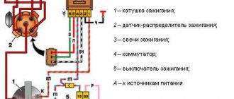
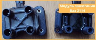
Ignition module
As mentioned above, the “ten” has 4 engine types: 16 and 8 valve internal combustion engines, as well as with a volume of 1.5 and 1.6 liters. This will lead to differences in the ignition modules. Depending on the installed engine with a certain volume, its own ignition module will be installed.
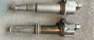
Differences
The main differences between the modules will be the size and mounting holes. In a 1.5 liter internal combustion engine, the ignition module is larger in size in contrast to the 1.6 liter engine. The cost of the modules depends on the manufacturers, but it should be noted that the MZ from a 1.5 liter engine is always more expensive than a 1.6 liter one.
16 valve MZ
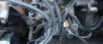
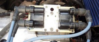
In a 16-valve internal combustion engine, the ignition module is installed on the valve cover near the oil filler neck.
8 valve MZ
The MZ on an 8-valve engine is installed on the front of the cylinder block between the dipstick and the breather.
Device
The ignition module has a common structure regardless of engine size. Inside the switch there are two high-voltage coils and an electronic circuit with many keys.
The coils are designed to switch high voltage and supply it to the spark plug to form a reliable spark in the combustion chamber of the engine.
The ignition module produces a spark in pairs, that is, each of the coils located inside the module is responsible for generating a spark on two cylinders: the first-fourth, the second-third.
Replacement
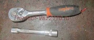
Replacement is quite simple and effortless. To replace, you will need a ratchet with an extension and a 10mm socket.
Replacement process
- We remove the negative mark from the battery, since the work is carried out on the electrical equipment of the car. This will avoid an unintentional short circuit in the vehicle's network.
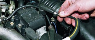
- We remove the high-voltage wires from the MZ and the power connector.
- We unscrew the nuts securing the MZ and dismantle it.
- Installation is carried out in reverse order.
Pay attention to the order in which the wires are connected. Do not confuse them, otherwise the car engine will not start. Cylinder numbering starts from the timing mechanism from left to right. Connect the wires as it is written on the Ministry of Health.
We hope our article was useful to you.
Symptoms of a problem
Based on some signs, it can be determined that the culprit of a malfunctioning internal combustion engine is the MZ. Below is a small list of symptoms indicating failure of the MH.
- Failure of two cylinders at once, namely 1-4 or 2-3;
- Increased fuel consumption;
- Detonation at idle speed;
- The engine does not develop power;
- Difficult starting on a hot internal combustion engine;
These signs indicate a malfunction in the ignition system. These signs also apply to other possible breakdowns: spark plugs, wires and even injectors, but first of all you need to pay attention to the MH.
Errors
A module malfunction can also be determined using an error scanner. Error codes associated with the module are:
- R-3000, R-3001, R-3002, R-3003 and R-3004 - gaps in sparking, the module itself, spark plugs, high-voltage wires or the ECU may be to blame;
- R-0351 - the coil of cylinders 1-4 does not work;
- R-0352 - the coil of 2-3 cylinders does not work.
The scanner readings do not yet indicate problems with the module itself.
It is possible that the spark plugs are not working or the high-voltage wires are broken, but if we initially diagnosed them, then the fault lies entirely with the ignition module. In this case, we can repair it ourselves, or buy a new one, which is faster, easier and guarantees uninterrupted operation of the ignition system. Good luck to everyone, strong spark and good roads!
Module check
After signs similar to failure of the ignition module appear, it must be checked before buying a new one, since its cost is not cheap.
There are three ways to check: substitution, visual inspection and a multimeter.
Substitution
The best and easiest way to check the MZ is to install another known good one from another exactly the same car. After which it will immediately become clear what the matter is and whether the Ministry of Health is to blame for this problem.
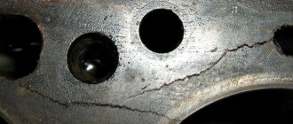
Visual inspection
It is necessary to inspect the module for chips, cracks, etc. There should be no damage to it. There should be no moisture or rust on the contact part.
Multimeter
Testing with a multimeter is carried out using the results of voltage and resistance measurements. This will help identify the cause of the failure of the module or its control circuit.
Step by step check
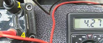
- Remove the power supply from the module. On the multimeter we set the DC voltage measurement limit to 20V. We turn on the ignition on the car and connect the multimeter contact on one side to the power block (namely to connector 15), and on the other side to the engine housing. The voltage between pin 15 and the motor housing must be at least 11-12V. Otherwise, the power supply circuit of the MH is faulty, or the battery is discharged.
- Next, we check the resistance on the VAZ 2110 ignition module itself. We set the multimeter to the resistance measurement parameter, namely 200 Ohms. We connect the multimeter probes to the high-voltage terminals of the MZ: 1-4, 2-3. The resistance of these coils, with a working MC, should be within 5 ohms.
- Then the resistance at the MC input is checked. One multimeter probe is connected to the central contact and the resistance is measured first on the leftmost contact and then on the rightmost one. The resistance should be in the 5 ohm range.
Diagnostic procedure
The diagnostic procedure can be as follows:
- Disconnect the connector with signal wires from the module.
Remove the connector from the module by moving the lock slightly and pulling the wire.
- Turn on the ignition and check the voltage at terminal 15 (central) of the control wire block. The rated voltage is 12 V. A drop or absence of voltage when the battery is charged indicates that the engine control unit does not supply power to the module. This means the reason lies in the ECU.
We check the voltage between pin 15 and the block ground.
- We remove the high-voltage wires, unscrew the module mounting bots and remove it.
Using a 13mm wrench, unscrew the bolts attaching to the cylinder block.
Unscrew the bolts securing the clutch housing.
Remove the module along with the bracket.
- We check the resistance of the primary windings of the coils - put the multimeter in resistance measurement mode and take readings from the rightmost and central terminals, then from the leftmost and central terminals. The nominal resistance of the primary windings is approximately 0.5 Ohm.
Scheme for checking the primary windings.
We measure the resistance of the secondary windings between terminals 1-4 and 2-3 high-voltage wires. Nominal value: 5.4 kOhm. If the readings do not correspond to the nominal value, the coil is not working correctly.
Scheme for checking secondary windings.
Check the module for a short circuit. To do this, install one tester probe on the central pin 15, the second on the metal body. The device should show the absence of a short circuit (one or infinity). Otherwise, one of the coils has shorted to the housing.
Scheme for checking the module for short circuit.
Cost and article
The table below shows the cost of the VAZ 2110 ignition module depending on the manufacturer and VAZ engine size.
| Engine volume | Number of valves | Manufacturer | vendor code | Price, (rubles) |
| 1,6 | 8 | JSC SOATE | 2111-3705010-03 | 905 |
| 1,5 | 8 | BOSCH | F000ZS0211 | 2600 |
| 1,5 | 16 | StarVolt | 2112-3705010 | 1600 |
| 1,5 | 16 | Omega | 2112-3705010 | 1590 |
We check the ignition module on the injection VAZ-2110 8 valves with our own hands
At different times, different engines were installed on the VAZ-2110 car, both carburetor and injection. However, regardless of the type of power system and the number of valves (8 or 16), all engines are assembled on the unit base of the old engine 21083 and 21093. The most progressive of these engines is the 16-valve 1.6-liter VAZ 21124 engine with a power of 89 horsepower. Today we will touch on the ignition module for 8-valve engines 2111 and 21114 (1.6 l), check its performance and find a suitable replacement for the failed module.
Version of the module on the 8-valve VAZ-2110
The top ten was equipped with two 8-valve engines of different sizes - 1.5 (2111) and 1.6 liters (21114). The ignition modules for these engines are different.
- The one and a half liter engine has a module with article number 2112-3705010,
- and the 1600 cc is equipped with module 2111-3705010.
A module for a 1.5 liter engine costs about 1500-2100, and the second one is 500 rubles cheaper.
Which is better?
SOATE devices manufactured in Stary Oskol have proven themselves to be the most reliable ignition modules.
Module structure
The module consists of two ignition coils and two high-voltage switch switches.
Inside the module there is a board with radio components and ignition coils filled with compound.
The coil generates a high voltage pulse, and it is a simple transformer with two windings, primary (induction voltage about 500 V) and secondary (induction voltage at least 20 kV). All this is assembled in a single housing, on which there is a connector for signal wires (from the engine control unit) and four terminals for high-voltage wires.
Schematic diagram of the module.
The module operates on the principle of an idle spark - it distributes sparks in pairs to cylinders 1-4 and 2-3 according to impulses transmitted from the ECU.
Repair
So, for the VAZ 2110 the most common problem is the disappearance of voltage on cylinders 2 and 3. After some time, the engine starts working normally again if you press the rear plate of the module.
You should not put up with such a situation; it is better to immediately check the functionality of the unit, restore or replace it completely.
Removing the module
The procedure is quite simple.
- Disconnect the negative cable from the battery.
- Remove the plastic cover that covers the motor.
- Remove the wires from the spark plugs.
- Disconnect the wires from the ignition module. Their numbering is indicated on special white rings. And the cylinder number is indicated on the ignition module housing.
- Disconnect the connector from the ignition module.
- Using a 10mm socket, unscrew the three nuts that hold the block we are looking for.
- Carefully remove it, after which you can begin further work.
Now let's move directly to working with the module:
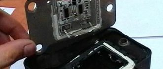
- Open the aluminum plate on the ignition module. A flathead screwdriver is useful for this.
- Inside you will find a small printed circuit board with electronic components. It is covered with a transparent layer of silicone, which will have to be removed.
- There are also wires that connect the board to the connector contacts. They are made of aluminum, so they can tear quickly.
- Tear off all the wires from the contacts, don’t be afraid. Others will be installed in their place. By the way, experts recommend using stranded wires used in computer mice.
- The ignition module circuit includes two switches and two powerful transresistors. If you decide to change these elements, you need to know that the switches are manufactured by SGS-THOMSON (model L497D1), and the transistors are of the BU931 type.
- The contacts are made of aluminum, so you will need a special flux to work with this metal.
- We solder the wiring to the board. It is more difficult to solder to the transistor collectors, since they are covered with a special material, the soldering of which is problematic. Therefore, try to hide the top coating from the element as carefully as possible. To prevent the soldering iron from transferring all the heat to the plate, place it on the stove and heat it to 180 degrees Celsius.
- Solder the wires to the contacts on the module so that they are as short as possible.
- Cover the areas where you soldered with varnish. Regular nail polish borrowed from your wife will do.
- Check if the ignition module is working.
- If everything is fine, coat the inner surface with a special autosealant, then reassemble in the reverse order.
- Upon completion of assembly, the wiring should be positioned fairly freely. Make sure that they are not compressed inside the box and that the integrity of the connections is not broken.
Carrying out such a repair of the ignition module on a VAZ 2110 with your own hands will not be difficult. But be careful, act carefully and consistently. Pay special attention to the soldering process.