A breakdown of the oxygen sensor in the exhaust system of a budget model of domestic origin Lada Kalina with an 8-valve engine can be observed quite often. This is directly influenced not only by harsh operating conditions, but also by the design features of the vehicle, and signs of malfunction are obvious.
If signs of a malfunction appear, many Lada Kalina owners seek to solve the problem themselves by replacing the sensor that has become unusable. This allows them to achieve certain cost savings by not having to visit the service.
Characteristic
An oxygen sensor is installed on the Lada Kalina car in order to determine the amount of remaining O2 in the exhaust. Another name for this sensor is lambda probe. This name comes from the Greek letter λ. This symbol indicates excess air in the exhaust gases. The sensor is designed not only to measure O2 concentration, but also to maintain stable engine operation in its different operating modes (since it is closely connected with the electronic control unit).
Troubleshooting
The malfunction may be in the UDC heater circuit and in the circuit of the sensor itself.
Error codes P0030, P0032 indicate a heater malfunction.
Checking the heater circuits is carried out for the power circuit and for the control circuit of the UDC heater:
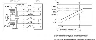
Connection diagram
- for the heater power circuit, turn off the ignition, disconnect the wiring harness block;
- disconnect the harness block from the controller. We check contact X1/C4 by shorting it to the vehicle’s on-board network;
- if there is no short circuit, then the controller is faulty;
- when there is a short circuit, disconnect the UD block;.
- check the closure of contact “D” of the UDC block to the on-board network;
- the presence of a short circuit indicates a faulty wiring harness;
- absence of closure with code P0032 means failure of the UDC.
All actions with the pads must be carried out with the ignition turned off!
When code P0030 occurs, we perform the following actions:
- The controller block must be in place;
- The UDC block must be removed;
- then turn on the ignition and check the presence of supply voltage at contact “B” (12V);
- lack of supply voltage means a break in the heater power supply circuit;
- Next, we check the resistance between contacts “B” and “D” of the UDC;
- We measure the voltage on contact “D” - if it is less than 1V, then there is a break in the UDC control circuit;
- if the resistance is more than 1 kOhm, the UDC is faulty;
- otherwise the controller is faulty.
Finding out the cause of a malfunction associated with the control oxygen sensor at home is quite difficult.
There is no point in buying a diagnostic device or a special pressure gauge for this. However, you can check the circuits connected to the sensor. If the sensor's power supply circuits are in good condition, it is possible to assume a failure of the UDC and carry out diagnostics in the appropriate place.
We check the exhaust system for leaks and repair them if necessary.
By external inspection we determine the integrity of the ceramic insulator, wiring harness, block and UDC contacts.
At the same time, expect that their repair is not allowed. If damaged, the sensor assembly must be replaced.
The UDC wiring harness and block are manufactured with structural air gaps to ensure adequate cooling.
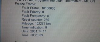
When an error is registered, “low oxygen sensor signal level” or “high oxygen sensor signal level,” the ECM continues to control the engine without taking into account the UDC signal.
Since this happens in power mode, you can confidently count on reliable operation of the engine with such malfunctions. In this case, the efficiency and effect of the presence of a catalytic converter are lost.
To check the oxygen concentration circuit, we check the circuit between the contacts:
- on the UDC block there is contact “C”, on the controller block there is contact 4;
- on the UDC block there is contact “A”, on the controller block there is contact 30;
- The controller block is installed in place and the ignition is on, between contacts “A” and “C” of the UDC block there should be a voltage of about 450 mV.
Having verified the integrity of the circuit and the presence of a controller signal, we assume that the UDC is malfunctioning.
After all the manipulations carried out, we can recommend the most radical method of checking - replacing the supposedly faulty one with an oxygen sensor installed after the converter!
Errors associated with the lack of UDC activity are described in detail here.
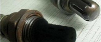
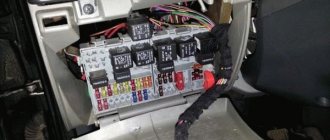
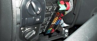
Location of the pads: the blue arrow indicates the control sensor pad, and the red arrow indicates the diagnostic lambda probe
Also, if the on-board computer displays UDC error codes, you need to check that the pads are connected correctly. The fact is that after performing various repair work, or after removing the cylinder head, there is a possibility of mixing up the pads of the control and diagnostic oxygen sensors (this, according to reviews on the forums, has happened more than once).
As a result, the ECM receives incorrect information. This manifests itself in the display of errors and “Check Engine” notifications. Therefore, immediately try to swap the pads in order to eliminate the error.
Air may enter due to cracks in the manifold and gaps under the gasket
If this does not help, then the reason may lie in air leaks in the “pants” area. Small cracks may appear on the collector itself, through which air can enter the collector. It can also penetrate when cracks appear under the manifold gasket. This can be detected by a sound, the place of origin of which is difficult to determine. A kind of “siphon” is heard, the muffler cuts. As a result, the control sensor begins to register an incorrect concentration of exhaust gases, errors occur, and the engine begins to “stupid.”
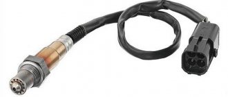
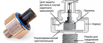
Device
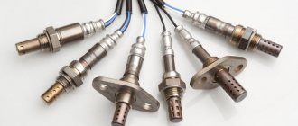
The lambda probe consists of the following elements:
- Ceramic insulator.
- Rings and cuffs (serve for high-quality sealing).
- Tip with drilled hole.
- Protective shield (also has a hole for exhaust gases).
- Spirals (it is placed in a separate tank).
- Conductive contact.
- Postings.
All this is enclosed in a metal heat-resistant case. The Kalina oxygen sensor is attached to the exhaust manifold using a threaded connection.
Note that the technical characteristics of the lambda probe do not allow measurements to be taken at temperatures below 250 degrees Celsius. In order for the Kalina oxygen sensor to show the correct values, its ceramic tip must warm up to operating temperatures. These are considered values of 300-400 degrees Celsius. But how does the element work when starting a car “cold”? In this case, the control unit uses average lambda values that come from other sensors (crankshaft speed and coolant temperature). A little more fuel is burned in the cylinders than required by the standards. But as soon as the temperature in the exhaust manifold reaches three hundred degrees, the fuel to oxygen ratio will return to normal and will be 1:14.7.
What and how can you check the lambda?
To check, you will need a digital voltmeter (preferably an analog voltmeter, since its “sampling” time is much shorter than that of a digital one) and an oscilloscope, if possible, the measurements will be more accurate. Before checking, you should warm up the car since lambda operates correctly at temperatures above 300C°.
First we look for the heating wire:
We start the engine, do not disconnect the lambda connector. We connect the negative probe of the voltmeter (ordinary gauge) to the car body. We “poke” the positive probe on each wire contact and observe the voltmeter reading. When the positive wire of the heater is detected, the voltmeter should show a constant 12 V. Next, using the negative probe of the voltmeter, we try to find the negative wire of the heater. We connect to the remaining contacts of the sensor connector. If a negative contact is detected, the voltmeter will again show 12 V. The remaining wires are signal wires.
Oxygen sensor "Kalina" 2nd generation
Note that the latest versions of Kalina have several such elements installed. The control sensor is still located in the exhaust manifold. And the second (diagnostic) is located behind the catalyst. Thus, the sensors measure the oxygen concentration before and after gases enter the neutralizer. Both lambda probes are closely interconnected. When one of them exits, a sensor on the instrument panel will immediately light up, indicating an error. But this is not the only symptom.
Operating principle
The control oxygen sensor is not dismountable, along with the wiring harness and contact block. As the name suggests, it changes the level of the reference signal depending on the amount of oxygen in the exhaust gases. The sensor signal is processed by the ECM. What is desirable to know about the principle of operation?
During engine operation, after the UDC has warmed up, the controller responds to changes in the signal range by depleting or enriching the fuel-air mixture. The controller's response to UDC readings is varied. This is a command, in the current process, to change the quality of the mixture and enter the last set of data into memory in order to call these modes in the process of subsequent work.
If the working part of the UDC has not heated up to 300 degrees Celsius, the sensor is not active - the signal level is zero. In a cold state, the resistance of the UDC sensitive element is several megohms. As the temperature rises, the resistance decreases and the signal level enters a certain range. There is a special heating element inside the UDC. Power is supplied to it, controlled by the ECM, using a relay in the circuit. Thus, on the block we have a controller circuit, a relay and contacts of the sensor itself.
The design features of the sensor are that its sensitive element is chemically active and can be “poisoned” by lead and silicon compounds (their vapors).
Possible causes of failure
- Leaded gasoline (the presence of lead compounds in the fuel) leads to failure of the UDC “for 4 tanks”.
- The use of silicone-based sealants (silicon compounds) during engine assembly can lead to the same results. Of course, if the assembly using sealants excludes contact with the power supply, exhaust, and ventilation systems, then the silicone will not harm (for example, when installing a pump housing).
- Contact of lubricants and water on the pad contacts, ceramic insulator.
- Mechanical damage to the housing, wiring harness, block, contacts.
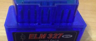
Method number 3
This method consists of computer diagnostics using an ELM adapter. For Lada Kalina, the optimal choice would be ELM-327. After connection, the computer reads all errors from the block. Below we list several codes indicating a malfunction of the Kalina oxygen sensor:
- PO134. No power to the sensor.
- PO136. The sensor shorts to ground.
- PO140. Talk about a broken circuit.
If you have a Kalina with a lambda probe heater, error PO135 may also appear. In this case, the element is also considered faulty.
Installation of the "blende"
For high-quality installation, welding equipment is required. Experts recommend installing the blende only in certified service centers.
- Welding machine;
- Sander;
- Metal pipe;
- Flange connections;
- Flashlight to improve visibility and visibility.
- Disable the existing oxygen concentration sensor;
- Use a welding machine to cut out the catalyst in the exhaust pipe section;
- Weld the metal insert;
- Screw in the spacer together with the DKK controller.
If the owner of a Lada Kalina wants to install electronic decoy, then this will require flashing the ECU with a portable scanner.
Source
Replacement
In order to replace the oxygen sensor on Kalina, you will need a set of open-end wrenches and WD-40 fluid. If the design provides only one lambda probe, it is not necessary to carry out work in the inspection hole. This sensor is located on the exhaust manifold - to get to it, just open the hood.
Please note: work on removing and installing the oxygen sensor must be carried out with the engine cooled down.
The lambda probe must first be treated with VD-40 liquid. What is it for? During operation, the thread strongly sticks to the manifold, so it becomes impossible to unscrew such an element. Next, remove the block with contacts. It can be mounted on a plastic clamp. The last one will have to be cut. The contacts themselves fit into the cooling system pipe. At the next stage, using a 22mm wrench, unscrew the oxygen sensor outward. Then all that remains is to install the new element in the reverse order.
Please note: the wires from the oxygen sensor must not come into contact with any metal part of the engine. Otherwise they may melt.
Finally, about fuel selection and prevention
In the vast majority of situations when the lambda probe has become unusable, it is substandard fuel. We recommend that you pay significant attention to the choice of refueling location. Do not be inclined to purchase gasoline from an unverified supplier, because in such fuel the risk of the presence of harmful impurities increases many times over. At the factory, the engine and fuel system are configured for a specific type of gasoline, which is then indicated by the manufacturer in the car's characteristics.
Also, a fairly effective measure to extend the life of the sensor is timely maintenance of the fuel circuit. A properly functioning fuel supply system will provide the LADA Kalina engine with cleaner exhaust, where the lambda probe can “feel more comfortable.” At the same time, its resource increases significantly. Otherwise, the sensor will need to be replaced.
If the lambda probe is sour
It often happens that wetting alone in the “VDshka” is not enough. The carving still holds its defense. What to do in this case? There are two methods to solve the problem:
- You need to start the engine and wait until it warms up. After this, carefully pour water over the sensor. According to the laws of physics, metal should shrink when cooled. And since the “pants” are still heated, a small gap forms in the thread. But you need to use gloves when unscrewing the sensor to avoid burns.
- The second method requires a hammer and a blowtorch. Using the latter, you need to heat the sensor body while simultaneously tapping it with a hammer. This way we will slightly loosen the element and it will be easier to unscrew it.