After the publication of my article on the topic of oil seals for the Niva, requests began pouring in to write the same regarding bearings and sensors for the 21214 engine, which is installed on Nivas, Niva-Ms, crocodiles and Shnivas. I’ll begin to slowly talk about “trouble-free” sensors, that is, those that you install and forget about for a very long time.
A few general words. Why did this question even arise? Let me give you an example: such garbage as a throttle position sensor (TPS). Since the electronics of our injector are taken entirely from their front-wheel drive counterparts, and their number is very large, a very large number of companies make spare parts for them, and there is no need to talk about the Chinese brothers at all. For some time I even saved up faulty TPS from different manufacturers in a box, after 7 I got lost and threw everything away)) While the factory supplies only two manufacturers.
Another example is the speed sensor. When it’s burned out, it happens that when driving through a puddle, the “check engine” lights up, or the engine simply starts to stall when coasting and nothing lights up. And when you reach the service level, like a wartime exterminator, suddenly the defect disappears. This means that water got inside the case and then also leaked out. So all is well......until the next puddle. One of the most basic sensors is the mass air flow sensor (MAF) , so a separate detailed article is devoted to it.
Niva with ECM
As you know, the first Russian SUV Niva was born back in the days of the Soviet Union. At that time, in the USSR they did not even think about an electronic engine control system; the entire process of operation of the internal combustion engine was mechanical. The engine was supplied with fuel through a carburetor. At present, the Niva still continues to be produced, but with its ancestors, the modern Niva has only the body left and it has undergone minor modifications.
The carburetor was replaced with an injector, the interior was changed and the appearance of the car was transformed, but still the Niva remained Niva. The legendary Niva cross-country ability did not deteriorate after these modifications, but became much more comfortable.
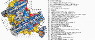
In this article we will talk about the sensors of the engine control system in the injection Niva, namely, it describes in detail each of the sensors, where it is located and what function it is responsible for, as well as the signs of sensor malfunction are described in detail.
Self-diagnosis procedure for Chevrolet Niva via OBD2 connector
Determine where the OBD2 connector is located
- From 1990-1994 they are equipped with an OBD1 (GM12) connector - 12 PIN.
- Since 1995, cars have been produced with an OBD2 connector - 16 PIN.
The location of the connector also depends on the type of connector. You can study this issue in the article: “Location of the diagnostic connector on the Chevrolet Niva”
Determine which scanner is suitable for your car
The selection of a scanner (adapter) for a Chevrolet Niva depends on the connector, as well as on the needs of the diagnostician / car owner.
To select diagnostic equipment, use the calculator: “Scanner selection for Chevrolet Niva”
Download the diagnostic program for the scanner
The diagnostic adapter requires software that can be installed on a laptop or smartphone/tablet. Auto scanners with their own software shell and display do not require software.
To select a program for the adapter, go to the section: “Programs”
Use the instructions and carry out diagnostics
When you purchase an adapter, instructions are included with the adapter. More detailed instructions on diagnostic scanners and descriptions of their operation are posted in the section: “OBD2 car scanner reviews”
Identify errors and decipher them
Error codes and their interpretation are displayed in the scanner program interface. You can also study the complete database of errors for your car in the section: “OBD2 error codes for Niva Chevrolet”
Make repairs according to the error code
The unit is repaired according to the decoding of the error (problem) or contact a car service to eliminate a particular malfunction.
Check errors again
Scan Tool Pro - budget multiscanner for Chevrolet Niva
A good choice for a novice diagnostician
Nowadays there are scanner models with different versions of firmware and chips on sale. Scan Tool Pro with firmware 2022 is the most stable version so far, and also has maximum compatibility with cars manufactured since 2001, including the Chevrolet Niva.
By following the link on the right you can get acquainted with the scanner for autodiagnostics “Scan Tool Pro”. This is an official dealer website that provides a 12 month warranty.
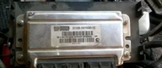
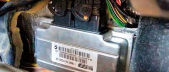
Electronic engine control unit (ECU)
An ECU is a kind of computer in a car; it is in this device that the entire operation of the internal combustion engine is corrected. All sensors that are installed in the car transmit readings specifically to this unit, and based on the readings, it makes changes to the operation of the engine, which affects both the engine speed and its consumption.
Symptoms of ECU malfunction:
There can be a huge number of signs of malfunction of this unit, because signs of failure of one sensor may even indicate failure of the unit.
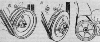
Interchangeability of electric fuel pumps
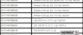
Until 2006. Since only one pump was installed on the conveyor, interchangeability is possible with other manufacturers who claim interchangeability. For example, Pekar produces pump 2123-1139009-20, claiming it as an analogue to the original one from Utes.
After 2006. This period can also be divided into several stages, using the FLS used as a basis.
K3. Pumps 00, 01, 02. As indicated in the catalogs, these three EBNs are interchangeable.
K3-01. Pump 10 can be used instead of pumps from group “K3”. In the opposite direction - GM-Avtovaz does not advise.
21236. Well, the last group, which includes pumps 15 and 16, are interchangeable with each other, and also interchangeable with 10. They can be used instead of pumps from the “K3” group, but GM-Avtovaz also does not recommend doing the opposite.
Mass air flow sensor (MAF)
This sensor is located near the Niva air filter box. Air flows through this sensor, which is necessary to form the air-fuel mixture. The sensor records the amount of air passing through it and sends signals to the electronic engine control unit (ECU).
Signs of a DMRV malfunction:
- Loss of vehicle dynamics;
- Increased fuel consumption;
- Unstable idling (speeds fluctuate);
- Difficulty starting the engine when the engine is warm;
Crankshaft position sensor (CPS)
The Niva DPKV is installed in a special hole in the oil pump drive cover. This sensor is responsible for setting the ignition timing. The sensor takes readings from the crankshaft pulley, which has teeth and in one of the places there is “caries”, that is, several pulley teeth are missing. It is “caries” that the DPKV understands in what position the crankshaft is. The sensor itself resembles an inductive coil, which generates impulses when the crankshaft rotates and transmits them to the computer.
If the sensors fail, the car will not start.
Signs of DPKV malfunction:
- The car does not start;
- The car stalls spontaneously;
- Uneven operation of the internal combustion engine;
Coolant temperature sensor (DTOZH)
DTOZH on Niva is installed in the cylinder head outlet pipe. The coolant temperature sensor is a fairly simple element in its design. The sensor is based on a thermistor, which changes its resistance as the temperature changes.
One of the functions of the sensor is to start the electric engine cooling fans when the coolant temperature threshold is reached. The sensor is also responsible for starting the engine in cold weather; according to the coolant temperature readings, the electronic control unit forms the fuel mixture necessary for more proper warming up of the car engine. This can be replaced by the presence of high warm-up speeds at the moment of starting the internal combustion engine.
Signs of DTOZh malfunction:
- Cooling fans do not work;
- No warm-up speeds;
- Difficulty starting the internal combustion engine;
- Increased fuel consumption;
Controller
The controller is a special-purpose mini-computer that consists of random access memory (RAM), programmable read-only memory (PROM) and electrically reprogrammable memory (ERM).
RAM is used by the microprocessor to temporarily store current information about engine operation (measured parameters) and calculated data.
Codes of any faults that occur are also recorded in RAM. This memory is volatile, i.e., if the electrical power is lost (the battery is disconnected or the wiring harness block is disconnected from the controller), its contents are erased.
The PROM stores the engine control program, which contains a sequence of operating commands (algorithms) and calibration data (settings).
The EPROM determines the most important parameters of engine operation: the nature of the change in torque and power, fuel consumption, ignition timing, exhaust gas composition, etc. The EPROM is non-volatile, i.e. the contents of its memory do not change when the power is turned off.
The EEPROM stores controller, engine and vehicle identifiers. Records operational parameters, as well as violations of engine and vehicle operating modes. It is non-volatile memory.
The controller is the central device of the engine control system. It receives information from sensors and controls actuators, ensuring optimal engine performance at a given level of vehicle performance.
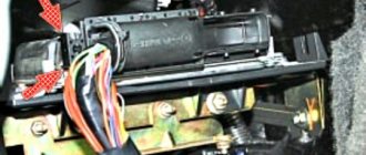
The controller is located in the passenger's foot area and is attached to the front panel.
The controller controls actuators such as the fuel injectors, electric throttle body, ignition coil, oxygen sensor heater, canister purge valve and various relays.
The controller controls the switching on and off of the main relay (ignition relay), through which the power supply voltage from the battery is supplied to the system elements (except for the electric fuel pump, electric fan, control unit and APS status indicator).
The controller turns on the main relay when the ignition is turned on.
When the ignition is turned off, the controller delays turning off the main relay for the time necessary to prepare for the next turn on (completion of calculations, setting the throttle valve to the position prior to starting the engine).
When the ignition is turned on, the controller, in addition to performing the functions mentioned above, exchanges information with the APS (if the immobilization function is enabled).
If the exchange determines that access to the vehicle is permitted, the controller continues to perform engine control functions. Otherwise, engine operation is blocked.
The controller also performs a system diagnostic function. It detects the presence of malfunctions in system elements, turns on the alarm and stores codes in its memory that indicate the nature of the malfunction and help the mechanic carry out repairs.
Mass air flow sensor
The engine control system uses a hot-wire mass air flow sensor with a frequency response of a digital output signal.
It is located between the air filter and the intake pipe hose.
The mass air flow sensor signal is a frequency (Hz) signal, the pulse repetition rate of which depends on the amount of air passing through the sensor (increases with increasing air flow).
The diagnostic tool reads the sensor readings as air flow in kilograms per hour.
If a malfunction occurs in the DTV circuit, the controller stores its code in its memory and turns on the alarm. In this case, the controller replaces the sensor readings with a fixed air temperature value (20 °C).
Throttle Position Sensors (TPS)
In a system with an EDP, two TPS are used.
TPS are part of the throttle pipe with electric drive.
The TPS is a potentiometric type resistor, one of the terminals of which is supplied with a reference voltage (5 V) from the controller, and the second is supplied with ground from the controller.
From the pin connected to the moving contact of the potentiometer, the TPS output signal is supplied to the controller.
The controller controls the throttle position electrically in accordance with the position of the accelerator pedal.
Based on the TPS readings, the controller monitors the position of the throttle valve.
When the ignition is turned on, the controller sets the damper to the pre-start position, the degree of opening of which depends on the coolant temperature.
In the pre-start position of the throttle valve, the output signal of TPS 1 should be within 0.65...0.79 volts, the output signal of TPS 2 should be within 4.21...4.35 V.
If you do not start the engine within 15 seconds and do not press the accelerator pedal, the controller de-energizes the electric drive of the throttle pipe and the throttle valve is set to the 7-8% throttle opening position.
In the de-energized state (LIMP HOME) of the electric throttle valve drive, the output signal of TPS 1 is in the range of 0.80-0.85 volts, the output signal of TPS 2 is in the range of 4.15...4.20 V.
Further, if no action is taken within 15 seconds, the check mode (“learning”) of the 0-position throttle valve will begin - complete closing and opening of the throttle valve to the pre-start position, and then the electric throttle valve drive will again switch to de-energized mode.
At any throttle position, the sum of the TPS 1 and TPS 2 signals should be equal to (5±0.1) V.
If a malfunction occurs in the TPS circuits, the controller de-energizes the electric throttle drive, stores its code in its memory and turns on the warning light. In this case, the throttle valve is set to the 7-8% throttle opening position.
Electronic accelerator pedal (EPA)
Vehicles with electronic throttle control use an electronic accelerator pedal that electrically transmits the accelerator pedal position signal to the controller.
The electronic gas pedal is located on a bracket under the driver's right foot.
The electronic gas pedal uses two accelerator pedal position sensors (APPS).
DPPAs are potentiometric type resistors that are powered by a 5V controller.
DPPA are mechanically connected to the drive from the pedal lever.
Two independent springs between the pedal arm and the housing create a return force. Receiving an analog electrical signal from the electronic control unit, the controller generates a signal to control the throttle position.
The output voltage of the DPPA changes in proportion to the pressing of the accelerator pedal.
When the accelerator pedal is released, the DPPA 1 signal should be within 0.46-0.76 V, the DPPA 2 signal should be within 0.23...0.38 V.
With the accelerator pedal fully depressed, the DPPA 1 signal should be within the range of 2.80-3.10 V, the DPPA 2 signal should be within the range of 1.40-1.55 V.
At any accelerator pedal position, the DPPA 1 signal should be twice as large as the DPPA 2 signal.
Coolant temperature sensor (DTOZH)
The sensor is installed in the engine coolant flow, on the outlet pipe of the engine water jacket.
The sensitive element of the coolant temperature sensor is a thermistor, i.e. a resistor whose electrical resistance changes depending on the temperature.
High temperature causes low resistance, and low coolant temperature causes high resistance.
The controller supplies a voltage of 5 V to the coolant temperature sensor circuit.
Knock sensor (DS)
installed on the cylinder block.
The piezoceramic sensing element of the DD generates an alternating current voltage signal, the amplitude and frequency of which correspond to the engine vibration parameters.
When detonation occurs, the amplitude of vibrations of a certain frequency increases. At the same time, the controller adjusts the ignition timing to dampen detonation.
Control oxygen sensor (UDC)
The most effective reduction in the toxicity of exhaust gases from gasoline engines is achieved with a mass ratio of air and fuel in the mixture (14.5-14.6): 1.
This ratio is called stoichiometric. With this composition of the air-fuel mixture, the catalytic converter most effectively reduces the amount of hydrocarbons, carbon monoxide and nitrogen oxides emitted in the exhaust gases.
To optimize the composition of the exhaust gases in order to achieve the greatest efficiency of the converter, closed-loop fuel supply control is used with feedback on the presence of oxygen in the exhaust gases.
The controller calculates the injection pulse duration based on parameters such as air mass flow, crankshaft speed, coolant temperature, etc.
To adjust the calculations of the duration of the injection pulse, information about the presence of oxygen in the exhaust gases, which is provided by the oxygen sensor, is used
The UDC is installed on the exhaust system pipe. Its sensitive element is located in the exhaust gas flow.
The UDC generates a voltage varying in the range of 50-900 mV. This output voltage depends on the presence or absence of oxygen in the exhaust gases and on the temperature of the UDC sensing element.
When the UDC is in a cold state, there is no output signal from the sensor, since in this state its internal electrical resistance is very high - several megohms.
As the sensor warms up, the resistance drops and the ability to generate an output signal becomes possible.
To operate effectively, the UDC must have a temperature of at least 300°C.
For quick warm-up after starting the engine, the UDC is equipped with an internal electric heating element, which is controlled by a controller.
The duty cycle of heater control pulse signals (the ratio of the duration of the on state to the pulse repetition period) depends on the temperature of the UDC and the operating mode of the engine.
If the sensor temperature is above 300° C, then at the moment of passing through the stoichiometry point, the sensor output signal switches between low level (50-200 mV) and high level (700...900 mV).
A low signal level corresponds to a lean mixture (presence of oxygen), a high signal level corresponds to a rich mixture (no oxygen).
Description of the circuit operation
The controller supplies the UDC circuit with a stable reference voltage of 1.6 V. When the UDC is not warmed up, the voltage of the sensor output signal is in the range of 1.2…1.6 V.
As the sensor warms up, its internal resistance decreases and it begins to generate varying voltages outside this range.
By changing the voltage, the controller determines that the UDC has warmed up, and its output signal can be used to control the fuel supply in closed loop mode.
During normal operation of the fuel supply system in closed loop mode, the output voltage of the UDC varies between low and high levels.
Oxygen sensor poisoning
UDC can be poisoned as a result of the use of leaded gasoline or the use during assembly of room temperature vulcanizing sealants containing large quantities of silicone (silicon compounds) with high volatility.
Silicone fumes can enter the crankcase ventilation system and be present during the combustion process. The presence of lead or silicon compounds in exhaust gases can lead to failure of the UDC.
Malfunctions of the UDC circuits, a sensor defect, its poisoning or an unheated state can cause the signal voltage to remain in the range of 1.2…1.6 V for a long time.
In this case, the corresponding fault code will be entered into the controller’s memory. Fuel supply control will be carried out in an open loop.
If the controller receives a voltage signal indicating a prolonged lean state, the corresponding fault code is stored in its memory (low oxygen sensor signal).
The cause of the malfunction may be a short circuit of the UDC output circuit to ground, a leak in the air intake system, or low fuel pressure.
If the controller receives a signal with a voltage indicating a prolonged state of richness of the mixture, the corresponding malfunction code (high signal level of the oxygen sensor) is entered into its memory.
The cause of the malfunction may be a short circuit of the UDC output circuit to the voltage source or increased fuel pressure in the injector rail.
When oxygen sensor fault codes occur, the controller controls the fuel supply in open loop mode.
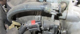
Throttle Position Sensor (TPS)
The TPS is installed on the throttle itself and is a potentiometer. This sensor reads readings from the throttle position and transmits them to the ECU. The damper opens access to air, thereby increasing engine speed. When the damper opens, the sensor sends a signal to the control unit to increase the fuel supply, which is necessary to form a working air-fuel mixture.
The sensor that most often fails is an unreliable element of the system. Subsequently, they abandoned it and switched to an electronic throttle.
Signs of a malfunction of the TPS:
- High speed at start-up;
- Jumps in engine speed;
- Increased fuel consumption;
- Not smooth idle;
Knock sensor(DD)
The knock sensor is installed on the right side of the vehicle's cylinder block. A DD is needed to catch detonations in the engine and adjust the fuel mixture. The sensor itself is made on the principle of a piezoelectric element and, in the presence of vibrations in the engine, transmits impulses to the ECU, which in turn adjusts the fuel mixture.
Signs of DD malfunction:
- Increased fuel consumption;
- Uneven operation at idle (increased vibrations);
- Jerks when the car moves;
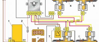
Basic elements of the electrical system
The vehicle's on-board network is designed so that all components and assemblies function smoothly, and control is as comfortable as possible. According to international standards, the voltage is 12V to be compatible with most consumers.
The circuit itself is single-wire. In practice, this means that the “negative” terminal is connected to the car body, and each individual device is powered by a “positive” wire. This greatly simplifies the routing of wires along the body and reduces the number of wires required. It also reduces the likelihood of cable damage and, as a result, a short circuit.
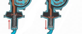
Oil pressure sensor (OPS)
The oil pressure sensor is located on the right side of the cylinder block and is screwed into the oil line fitting. This sensor is necessary to monitor the oil pressure in the engine. As you know, operating a car with low oil pressure in the internal combustion engine can damage it. When the oil pressure in the internal combustion engine decreases, the sensor closes the contact and sends a signal to the Niva instrument panel, lighting up the oil pressure indicator in the form of a red oil can.
Signs of DDM malfunction:
- Constant lighting of the oil pressure lamp;
- Oil leak from the sensor junction;
How to diagnose and replace
First, you should find the probe connector by placing the car over the inspection hole. You can simply disconnect the chip from the block with wires and unscrew the probe from its socket with a key, and then check the sensor with a multimeter.
Use a multimeter to set the resistance measurement and check the terminals of the heating element, usually 3 and 4. The resistance should vary between 12–45 Ohms. If it tends to infinity, then the heating element is faulty.
Also, there may be no power to the heating element. To check it, you need to disconnect the chips. Connect the multimeter to those connectors in the chip with the wiring harness that connect to the heater (usually 2 and 4). 4 - positive, 2 - negative probes and measure the voltage, after turning on the ignition. If there is no voltage, a wiring check is required.
A more accurate diagnosis of the voltage output signal is done with the vehicle running. From the back of the connector, into terminals 1 (signal+) and 2 (ground), you need to insert two thin metal tips, maybe paper clips, to connect to the multimeter probes. The positive probe goes to the signal, and the negative one to ground.
Select neutral speed, put the lever on the brake, jack up the front part of the Niva and place it on some kind of support. Turn on the ignition and use a multimeter to observe the voltage changes coming from the probe.
Until the sensor warms up, the motor operates without its participation (open cycle), and the readings on the device should correspond to 0.1–0.2 V. After 2–3 minutes, after the engine warms up, the readings should go up and run from 0.1 to 0.9 V. If the signal and then remains low, as at the beginning of warming up, or reaches its limit with deceleration (after 10 minutes or more), then the oxygen sensor requires replacement.
Replacement is carried out in the same sequence. You need to disconnect the old probe after the engine has cooled down, placing the car on an inspection hole. First, the chips, having first moved the latch, then the threaded connection of the sensor itself.
Idle air control (IAC)
This sensor is located, just like the TPS, on the Niva’s throttle valve. The essence of the sensor's operation is to open and close the channels through which air flows to operate at idle speed. The IAC is involved in the operation of the internal combustion engine only at idle; when the speed increases, the regulator is switched off. IAC is a kind of DC motor with worm gear. Quite often the sensor fails. Subsequently, this sensor was abandoned in favor of an electronic throttle.
Signs of IAC malfunction:
- Lack of XX speed (engine stalls);
- Increased speed at idle;
- Increased fuel consumption;
Tachometer speed does not work - why does the needle “jump”
Here are some tips from experienced car owners:
- look for the Check indicator (if there is no signal, self-diagnosis will not help);
- check connections and voltage with a tester;
- in case of parallel incorrect operation of other devices, test the “ground”;
- inspect the distributor parts;
- check the condition of the circuits;
- If problems occur at high engine speeds, diagnose the switch.
If, as a result of repair work, the tachometer does not work well, adjustment is required (adjusting the “0” position and the unit, checking the quality of connections).
The tachometer on the instrument panel does not work? Replace it. In theory, this is not difficult, but it is better to find detailed video instructions in advance (select the option specifically for your engine - diesel or gasoline).
Before purchasing a unit, be sure to check its compatibility with the machine.
Phase sensor (PF)
The phase sensor, also known as the camshaft position sensor, is installed in the cylinder head plug. Designed for phased fuel injection. Reads readings from the camshaft and transmits them to the computer; these readings are necessary for accurate distribution of the fuel mixture between the cylinders.
Signs of DF malfunction:
- Increased fuel consumption;
- Increased engine vibrations;
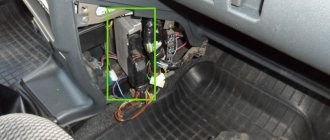
Brake pedal sensor
The brake pedal sensor is installed on the pedal assembly under the Niva's steering column. In cars without the E-GAZ system, it is only responsible for turning the brake lights on and off. In cars that have an electronic throttle and therefore an electronic gas pedal, this sensor affects the operation of the pedal. If the brake sensor breaks down, the gas pedal stops working.
Signs of malfunction:
- The gas pedal does not work;
- Jerking when moving at a constant speed;
- Loss of power and vehicle dynamics;
Camshaft
The Niva Chevrolet camshaft sensor creates stable engine operation. The work is based on the Hall effect. Thanks to it, the tilt of the gas distribution device is controlled according to the crankshaft. The system that controls the operation of the spark plugs and the flow of gasoline receives a corresponding signal. It works based on monitoring the potential difference of the required electricity, and is associated with the operation of the crankshaft position analyzer. Simply put, it informs the location of the piston of the internal combustion engine cylinder, while all cylinder stroke cycles occur sequentially. If it stops working, the device and indicator turn on, thanks to which a mixture of air and fuel occurs, dosing is suspended and the reserve mode is activated. Replacement is recommended every five years. If it is faulty, the on-board computer will display the following errors, PO343, PO342, PO340.
Speed sensor (DS)
The speed sensor of the Niva car is installed in the transfer case. The function of the sensor is to transmit vehicle speed readings. The sensor also forms the fuel mixture; when the car is moving at neutral speed, you can notice that the speed is slightly higher than when the car is running at XX while standing still. Increased speed when driving is necessary to avoid dips when turning on the speed and sharp acceleration.
Signs of DS malfunction:
- Increased fuel consumption;
- There are no increased speeds when driving at neutral speed;
- Dips during acceleration;
- The speedometer does not work;
Causes of tachometer malfunction
Most often, a sign of a broken meter is “inappropriate” needle behavior. If it freezes or twitches, you need to look for the source of the problem. In this case, it is worth repairing or replacing the device.
If the tachometer does not work, the “leading” functions of the car do not suffer. But experienced car owners warn that incorrect readings from the device do not allow timely identification of a problem with the engine. If you ignore this, there is a risk of facing the need for repairs or even installation of a new power unit.
If the tachometer does not work, the reasons may be the installation of silicone prototypes of the factory ignition wiring (the arrow twitches). This happens due to a change in the electric current pulse. To diagnose the problem, lower the resistor value on the transmission board. Also check the speed sensor - it may be transmitting erroneous data. And, of course, there is always the possibility of failure of the device itself.
Oxygen sensor (DC, lambda probe)
An oxygen sensor, also known as a lambda probe, is installed in the exhaust system of a car. In some versions of cars, two sensors are installed before the catalyst and after the catalyst. Two sensors are installed in Niva with EURO-4 standards. The sensor captures exhaust gases and transmits readings to the ECU. If there is a large amount of unburned gasoline in the exhaust gases or, on the contrary, a small amount, then the DC makes changes to adjust the fuel mixture.
Signs of DC malfunction:
- Increased fuel consumption;
- Loss of vehicle dynamics;
- Poor engine starting;
Where can I buy
Spare parts and other products for the car are easily available for purchase at auto stores in your city. But there is another option that has recently received significant improvements. You no longer need to wait a long time for a parcel from China: the AliExpress online store now offers the opportunity to ship from transshipment warehouses located in various countries. For example, when ordering, you can specify the “Delivery from the Russian Federation” option.
Follow the links and choose:
| Lambda oxygen sensor for Lada, Niva, Samara, Kalina, Priora, UAZ, Chevrolet | Car diagnostic scanner Elm327 V1.5 for Niva | Adapter for LED car lamps T10,T20,1156,1157,B9S |
| ALLSOME HT1190 Brake Fluid Hand Pump Liner Tools Vacuum Gun | VC100 film thickness gauge, paint | Pressure gauge for fuel pump, 0-140 PSI |
Ignition module (IZ)
The ignition module is installed on the left side of the engine on a bracket. This sensor is involved in the formation of ignition. It is this that produces the high-voltage voltage necessary to create a spark in the combustion chamber of the internal combustion engine. The module has two coils, they are also autotransformers, which produce a spark in pairs, each coil for two cylinders. If one of the coils fails, two cylinders fail at once.
Signs of malfunction of the MH:
- Troubles the engine;
- Increased fuel consumption;
- Increased engine vibrations;
- Loss of traction and dynamics;