Reading time
Difficulty of the material:
For fans - 3 out of 5
To carry out diagnostic operations on the “Ten”, including for flashing the ECU, you need to know the location of the service connector for connecting equipment (adapter, programmer, auto scanner). This material provides all the necessary information.
For VAZ 2110, the type and configuration of the connector depends on the year of manufacture, engine and ECU type:
Where is the diagnostic connector for the VAZ-2110?
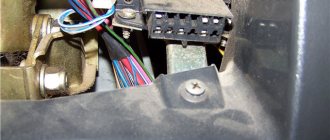
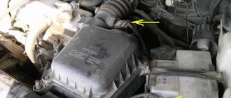
VAZ 2110 with a “European panel”, the diagnostic connector is located at the bottom right of the steering column. The block is closed with a decorative cover.
- 12-pin connector: All injection models were equipped with this, except for individual assemblies after 2002, which had an OBD-II connector installed.
- 16-pin connector: This was equipped with some models released after 2002, which were equipped with BOSCH MP7.0 Euro-3, BOSCH M7.9.7, January-7.2 control systems.
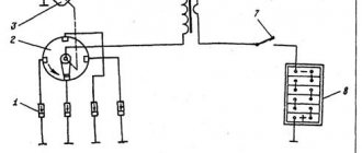
The location of the connector is indicated in the diagram in position No. 3. The following are also visual photos of the diagnostic block.
About the ECU and its location is written in the article “Diagnostics of the VAZ 2110”. The following shows the pinout of the OBD2 and OBD1 connectors, as well as the assignment of the contacts of some electronic control units that were installed on the “Tens”
Connector type No. 1—16-pin OBD-II connector in the shape of a trapezoid:
Brands and years: some models after 2002 with control systems BOSCH MP7.0 Euro-3, BOSCH M7.9.7, January-7.2, January-7.3.
Connector type No. 2 - 12-pin rectangular connector: Make and year: all injection models, except for some models after 2002 that have an OBD-II connector
ODB connector pinout: convenient pin layout
In order to personally diagnose a VAZ-2110 car through the connector located under the steering column, you need to know where to connect this or that equipment. This task is greatly facilitated by pinout, which is a diagram of the placement of contacts. It identifies the following main outputs:
- A – ground from the car battery is connected to this output;
- B – output is intended for connecting L-Line type equipment. It is not used on all modifications of the VAZ-2110, so be sure to pay attention to this when choosing a computer scanner or adapter;
- M – K-Line type devices are connected to this output. They are rightfully considered the optimal choice for self-diagnosis of the VAZ-2110, as they provide excellent interaction with any computer equipment;
- H – output to which power is supplied during diagnostic operations;
- G is a very important pinout element, since it is it that ensures safety control of all procedures performed and eliminates any short circuits or other emergency situations.
Connecting the VAZ 2110 on-board computer. How to install the on-board computer
If you have already decided or, moreover, purchased an on-board computer for your ten or another modern model of a domestic VAZ car, then the time has come to install it. For those who are just thinking about buying a BC, we recommend that you read the previous article on choosing an on-board computer for a VAZ.
Installing an on-board computer is not difficult and will take you half an hour. As a rule, the BC package already includes a contact block with the help of which connection is made to a special connector of the car. For those who don't know, the socket is located on the lower right side of the torpedo.
For additional information, a few words about the pinout of the connector for connecting the on-board computer.
As you can see, in the image shown, after connection, the on-board computer has access to all the main elements of the vehicle’s electronic on-board network. To fully launch the BC, all that remains is to connect the K-line.
What is a K-line and why is it needed?
The K-line is the channel through which the most important information is received by the bookmaker. Using this connection, data on errors that occur during engine operation, as well as its temperature, and other important diagnostic information will be available. The K-line wire is connected to the main connector, which is located under the steering column to the left of the driver's seat. Using a special wire, which also comes with the on-board computer, we make the connection as shown in the image shown.
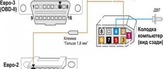
And finally, about the diagnostic connectors of the VAZ 2110. In total, there are two types of contact blocks Euro-2 (GM) and Euro-3 (ODB-II); the photo shows the pins to which the K-line must be connected when installing the on-board computer on the VAZ 2110 .
When is diagnosis necessary?
Computer diagnostics involves reading error codes, erasing them and correcting them. For this, various diagnostic adapters and systems are used. These include multifunctional stands, OBD connectors, portable readers and other devices. Thanks to diagnostic equipment and software, the slightest malfunctions in the vehicle’s control system and its main components are detected.
Using diagnostic systems, you can change parameters to increase the power characteristics of the machine. If a new car model comes out, you can reprogram the functions for the new equipment.
Computer diagnostics are usually carried out in the following cases:
- indicators on the dashboard light up, signaling any malfunctions;
- the driver has suspicions of a malfunction of any components or systems;
- check the condition of a used car before purchasing;
- Experts recommend diagnostics at least once a year.
How to calibrate the FLS on a standard BC
An important parameter is the fuel level in the tank. For the sensor to work correctly, it must be calibrated. For this:
- Empty the fuel tank completely.
- Switch to mode to select the fuel type. To do this, press and hold the first top button in the right row. The display will show "0".
- To switch to tare mode, you must press and hold the button with the car on it. The on-board computer on the VAZ-2110 will emit a short signal.
- Fill the fuel tank with 3 liters of gasoline.
- After a few seconds, press and hold the car button again. The on-board computer display should indicate that there are 3 liters of fuel in the tank.
- Gradually fill the tank and press the button after each addition.
- After maximum filling, the on-board computer will turn off - this completes the calibration.
So that after installing the VAZ-2110 on-board computer, it notifies you that the maximum permissible speed is exceeded, you also need to carry out “training”. To do this, switch to the average speed input mode and hold the button (top right) for several seconds. To enter an integer number corresponding to the speed, you need to use the “” “–” buttons on the front panel of the device.
READ Where are the downloaded files in Samsung?
How to diagnose a car
- Connect contact “B”, which has the diagnostic block and “ground”;
- Turn the ignition key to the third position, do not start the car;
- First, the “CHECK ENGINE” lamp displays code 12 with 3 flashes. It shows that the diagnostic programs are working. On the VAZ 2110 this happens in this order: the lamp blinks briefly 1 time (which should be considered the designation of number 1). After a pause lasting at least 2 seconds, it flashes 2 times in a row (two). So we got the number two. And this is repeated 3 times so that the driver understands these signs;
- After the diagnostic program has declared its serviceability, it will begin to display error codes, if there are any, of course. In the same way - flashes and pauses.
Lada 2110 OneTen › Logbook › Block for connecting the trip computer (BC).
Block for connecting the trip computer (BC, in my case the device is Multitronics SE-50).
VAZ cars of the tenth family have a standard connector for connecting the on-board computer to the car. That is, to install the BC, everything is already provided by the factory, this is the first thing that is needed. The second is connecting the control line from the electronic control unit to the trip computer. Connection is carried out according to the following instructions:
Connecting the K-line and assigning contacts to the BC block
Types of diagnostic pads
Some of the wires of the trip computer connector had to be restored because they were torn out; it was not originally installed in the car.
Ready connector BC
The automatic switching on of the interior lights was implemented through the on-board display unit, but it is now missing. Therefore, to preserve this function, it is necessary to connect the following contacts according to the diagram:
Why does the OBD2 GM12 pin adapter for VAZ, Daewoo not work?
Having ordered an OBD2 - GM 12pin diagnostic cable and connecting it to a VAZ family car, many are faced with various troubles.
The best, so to speak, of which is simply the impossibility of diagnosing the car, but there are also cases where the fuel pump turns on or there is a short circuit in the electrical wiring, and if you’re lucky, the matter will be dealt with by simply replacing the fuses.
After such experiments, the average person takes the cable in his hands and, waving it, scolds the seller and the manufacturer.
The above troubles are usually a consequence of incorrect cable pinout, that is, power is supplied to the device along the wire through which information is to be read, or power is supplied to the fuel pump along the wire through which power is supplied. And what do you tell the latter to do? Right! Turn on and work.
But no matter how strange and incomprehensible everything now turns out to be, and it may sound absurd, the cable actually turns out to be serviceable and working. Yes, yes, workers, and even the pinout is correct. Correct, but not suitable for our car brand.
How so? You ask? And the answer here is simple. The cord is only intended for a different brand of car, and this brand is called nothing less than DAEWOO.
That's basically it. Having the same connectors for diagnostics on VAZ and DAEWOO cars
We have different pinouts, which means that just because the cord fits into the socket, this does not mean that by connecting it it will work and will not cause detrimental consequences to the electronics of your car.
And so, let's figure out what cable is needed and what pinout it should have to diagnose a VAZ car.
To diagnose AvtoVAZ before 2005, you need to connect three wires to the diagnostic block:
VAZ OBD2 and GM 12pin Correct pinout
Electrical connections
During the preparation stage, you must perform the following steps:
- Disconnect the negative terminal from the battery.
- The VAZ-2110 on-board computer is connected to the alarm block. Find it and position it as conveniently as possible.
- You will need to first locate the orange wire (at pin seven).
- Connect the red-white wire to it, which is located in the computer connection harness.
- To the red-black wire installed in the tenth pin, connect the red one from the harness coming from the trip computer.
- And connect the red on the block with the red-black coming from the BC harness.
- Find the black wire on the fifth pin. And you connect the same one from BC to it.
- A white wire is installed on the eighth contact, which you connect to a similar one going to the BC.
READ How to Set up Internet on a Computer Via Modem
instruction manual on how to connect and configure the BC
The VAZ-2110 on-board computer is used to control vehicle systems. In its original configuration, the car leaves the factory without a smart gadget, but this does not prevent the driver from purchasing it. Before this, it is necessary to evaluate the technical characteristics of the models on the market. Each of them is designed for specific operating conditions of the VAZ-2111, 10 or 12.
Functional purpose of the device
The development of the technical component of vehicles has led to an abundance of electronic and mechanical devices that control the operation of the car. Each of them reflects one or another indicator, which a person does not always have time to analyze. This is where the VAZ on-board computer will help, taking control of what is happening. In addition to monitoring the operation of vehicle systems, it will promptly inform the owner about a failure.
Another advantage is that the standard on-board computer analyzes the technical condition of the car within the specified parameters. In practice, this means that the driver can ask a question regarding the presence of components or assemblies whose performance exceeds the technical norm. Preventative analysis reduces the likelihood of downtime due to technical failure. The VAZ trip computer differs in the available options depending on the configuration:
- Carburetor is a budget option that does not have sufficiently wide functionality. Installation does not take much time, and operation is simple. It is difficult to find it on the market due to low demand among VAZ-2110 owners.
- Injection - there are various options on the market that take into account the needs of drivers. Among the main advantages is the ability to conduct in-depth diagnostics. For example, if the car does not start because the injector has failed, the system will notify you in advance. The cost of the on-board computer depends on the configuration.
- Universal - installation is carried out on a VAZ-2111, 10 or 12 without taking into account technical specifications. Installation is carried out behind the rear view mirror or windshield.
- Adapted - selected taking into account the make and model of the vehicle. Installation is carried out in a strictly designated place, which the instructions will help you find.
Installation recommendations
The efficiency of the device is determined at the stage of selection and subsequent installation. An on-board computer (BC) is selected for the VAZ-2112, which collects and analyzes incoming information. Regardless of the model, it is equipped with a Check Engine light. When it is triggered, the bookmaker will independently determine that it is not working.
Experienced drivers do not advise overpaying for sensors of humidity and outdoor temperature levels, a chronometer, and an alarm clock. These indicators are easy to obtain using a standard VAZ-2110 thermometer. Once the driver has made his choice, installation can begin. First, you should study the passport supplied with the device, which will tell you how to connect the on-board computer.
When operating a vehicle, only 1 BC is required. The presence of a second computer in most cases provokes failures in the operation of both systems. Connection to the VAZ-2112 is carried out via a 9-pin block. It is located behind the BC and has a trapezoidal shape.
A diagram of the vehicle and the on-board computer itself will help you connect the contacts correctly. To connect to the VAZ-2110 in the standard BC, contacts No. 10 and No. 11 are not used. They are intended for temperature, humidity and pressure sensors. The installation of the BC is completed by connecting the K-line. Mistakes cannot be made, otherwise the indicators obtained from the VAZ-2112 will be inaccurate.
The connecting line runs in the diagnostic block provided for it. When checking valves and other preventive inspections at a service station, it is into the block that the technician looks into the block to connect the equipment. When laying the cable, you should make sure that there are no bends and that it is close to moving elements. For example, when operating a vehicle, the K-line can be damaged by the gas pedal.
Troubleshooting BC
Malfunctions occur with BCs of various modifications. It would be useful for the owner to know what to do in such cases. Many failures occur when the on-board computer was not installed properly. First, you need to check the reliability of the connections. Secondly, there is a high probability of accidental damage or pinching of the K-line. Multitronics itself will report this, displaying obviously incorrect data.
It is inexpensive, and the entire replacement procedure will take no more than 60 minutes. More time will be required if the problems of the on-board computer 2110 are caused by broken contacts. It is necessary to disconnect the device after performing a visual inspection. If bent plugs are still present, you should select new ones from the store and resolder them.
Using the BC on a VAZ passenger car allows the owner to always be aware of the technical condition of the car. The device is selected based on needs. Its effectiveness depends on correct installation.
If you have already decided or, moreover, purchased an on-board computer for your ten or another modern model of a domestic VAZ car, then the time has come to install it. For those who are just thinking about buying a BC, we recommend that you read the previous article on choosing an on-board computer for a VAZ.
Installing an on-board computer is not difficult and will take you half an hour. As a rule, the BC package already includes a contact block with the help of which connection is made to a special connector of the car. For those who don't know, the socket is located on the lower right side of the torpedo.
For additional information, a few words about the pinout of the connector for connecting the on-board computer.
As you can see, in the image shown, after connection, the on-board computer has access to all the main elements of the vehicle’s electronic on-board network. To fully launch the BC, all that remains is to connect the K-line.
What is a K-line and why is it needed?
The K-line is the channel through which the most important information is received by the bookmaker. Using this connection, data on errors that occur during engine operation, as well as its temperature, and other important diagnostic information will be available. The K-line wire is connected to the main connector, which is located under the steering column to the left of the driver's seat. Using a special wire, which also comes with the on-board computer, we make the connection as shown in the image shown.
And finally, about the diagnostic connectors of the VAZ 2110. In total, there are two types of contact blocks Euro-2 (GM) and Euro-3 (ODB-II); the photo shows the pins to which the K-line must be connected when installing the on-board computer on the VAZ 2110 .
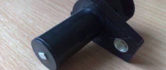
Checking the DPKV for serviceability
Also, the motorist should not forget to measure the clearance between the synchro disk and the sensor before dismantling, which cannot go beyond the size of 0.6-1.5 mm. If there are no mechanical damage such as scratches, dents, or damage to the material structure, the sensor is checked using other measuring instruments:
checking with an ohmmeter. In this case, it is necessary to measure the resistance of the sensor winding
Since the standard value of this indicator, set by the manufacturer, ranges from 550 to 750 Ohms, going beyond the specified limits indicates the malfunction of this device, which is important for the correct operation of the car - which means it is faulty. It is worth noting here that the manufacturer still allows a slight discrepancy in resistance with the nameplate values, but in any case they must correspond to the data specified in the machine’s operating instructions; checking with a voltmeter, inductance meter and transformer
This method is more complicated, but more effective - the resistance is measured with the same ohmmeter, after which the inductance is checked (should be from 200 to 4000 millihenry), with a sensor winding voltage of 500 Volts. Next, you need to measure the resistance with a megger and make sure that it does not exceed 20 MOhm.
If the sensor still does not pass these tests, it must be replaced. During this procedure, it is necessary not to forget about the distance between it and the synchronization disk regulated by the manufacturer, as well as alignment with the marks on the crankcase that were made on the previous device. Before installing a new sensor, be sure to check it, since even if all installation procedures are followed correctly, it may not work properly.
A new DPKV is checked according to the same procedure as a supposedly faulty one, and based on the test results, the device can be installed instead of the previous one or rejected. When installing, the bolts are tightened with a torque of 8 to 12 Nm. However, in any case, before carrying out all the actions to replace a rather expensive and hard-to-reach component, you should definitely make sure that it is the one that has failed, because cars produced by our automotive industry can often bring unpleasant surprises.
First way to check
In this case, you will need an ohmmeter with which you will replace the resistance on the winding. According to the manufacturer's standards, the indicator ranges from 550 to 750 Ohms.
It's okay if your numbers are slightly different from the norm. If the deviations are serious, you will definitely have to replace the sensor.
It should be noted in fairness that the crankshaft position sensor on VAZ 2110 models rarely breaks down. Among the main reasons for its failure to function normally is the accumulation of dirt, mechanical damage, as well as banal factory defects.
Features of testing on other cars
As for other cars, for example, VAZ-2109 with an injection engine, VAZ-2112 and VAZ-2114, their check is carried out identically to the VAZ-2110 car.
It is noteworthy that for VAZs, when checking the resistance of the crankshaft sensor coil, an additional check can be carried out.
But to do this, the multimeter must be switched to voltmeter mode with a measurement limit of 200 mV.
Then connect the probes to the DPKV terminals and pass them with any metal object, for example, a screwdriver, at a short distance from the core.
If the sensor is working properly, it will react to metal, the multimeter will show voltage surges on the display. The absence of these bursts will indicate a faulty element.
As for a car like the Reno Logan, the difference from the VAZ in this car comes down to slightly different readings of the resistance of the sensor coil when measured with an ohmmeter.
A working Logan DPKV has a normal resistance of 200-270 Ohms.
For Daewoo Lanos, the coil resistance should be in the range of 500-600 Ohms.
But on the ZMZ-406 engine, installed on Volga and Gazelle cars, the normal coil resistance is in the range of 850-900 Ohms.
Second method
Here you will need a voltmeter, a transformer and an inductance meter. It is advisable to measure resistance under compact temperature conditions.
Once the ohmmeter readings are obtained, arm yourself with an inductance measuring device. Normally, the device should show from 200 to 4000 units (millihenry).
A megger measures the resistance when the crankshaft position sensor winding is powered at 500 volts. Under normal conditions, the readings will be no more than 20 MΩ.
Lada 2110 Green Arrow › Logbook › Do-it-yourself diagnostics using the K-line, part 1
Aleksandr Matskovich, 29 years old I drive Lada 2110 Green Arrow Kryvyi Rih, Ukraine
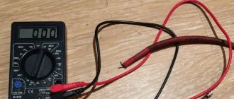
Good day to everyone who is reading this entry! And so I’ll start with the fact that I don’t have an on-board computer, I have a desire to install it, but more on that later. There was an interest in identifying my car with my own hands. In one of the previous articles, I wrote that after a rainstorm I filled up the air flow sensor, the check light came on and I went for diagnostics: they charged me 100 UAH. Within 30 seconds, having discovered that the sensor does not work, it needs to be replaced. I don’t need professional diagnostics; if necessary, I’ll go to a diagnostician, and for easy diagnostics, I decided to buy a K-line scanner
VAG-Com 409.1 K – Line scanner
oh, and even though my car is from 2004, it is 1.5l and 8kl with EURO-2, and is equipped with an ODB-1 connector. I googled it: it turns out that ODB-2 was already installed but on 16kL cars with EURO-3 from earlier years. I also had to buy an adapter with
Adapter OBD-II 16pin to GM12
I ordered everything from the online store, along with the cords I received a disk with programs for diagnostics and a bunch of different information on diagnostics. I configured all the com ports on the laptop and went into the garage with the laptop to try. I plugged it in, turned on the ignition, bam, and the fuel pump immediately began to hum without stopping. Naturally, nothing happened and I abandoned the matter (and this was last year at the end of autumn). Well, it’s already warm - there is a desire to resume this business. When I rang the adapter, I didn’t really understand anything, one rings 3 at a time, some don’t ring at all, I decided to redo it all. As you know, for diagnostics via the K-line you only need 3 wires (channels): 1) potassium itself 2) +12V 3) -12V aka ground, ground
I would like to note that in the figure above the contacts on the adapter are drawn as they should be, and not on the adapter or block! So imagine applying the adapter and think about where the contacts on the adapter and block should be, here is the picture below
location of K-line contacts on the blocks
Lamaaat adapter! Well, what can you do, the design is not collapsible (breaking the connector turned out to be not an easy task))) the black body is very hard, everything inside is still filled with white plastic. 4 wires are soldered, everything is called where which goes to the adapter where is the K-line, +12 and ground, the fourth, judging by the continuity, is the L-line, which we do not need. I’ll connect these 3 wires directly to the diagnostic block and try to connect to the ECU again! Good luck for me! Read the continuation!
Price tag: 300 UAH
Most often, the solution to the problem really lies in breaking the K-line wire. That is, the wire has simply moved slightly out of the block (the APS block of the immobilizer, or the BC block) and there is no longer any contact. If you have checked all the contacts, but the on-board computer still does not see the K-line wire, then you can proceed as follows:
2) If on your VAZ the connector with the APS is disconnected, then check for the presence of a jumper in the APS block between pins 9 and 18.
3) The problem may be in the immobilizer (the K-line signal comes, but disappears after the immobilizer). Check for the presence of a K-line on pin 18 of the APS block. Using the same method, you can check whether there is a break between the APS block and the BC block.
4) Interference or broken wire. Try replacing the wire from the BC to the diagnostic connector with a new, shorter one.
You can also check the k-line in a service center using computer diagnostics, or by connecting a known working on-board computer to the car (see how to connect a BC). And if the k-line does not work and at the same time there are problems with starting the engine, then start checking additional VAZ fuses.
K Line connection problems
K - Line adapter ( VAG COM ) does not connect
When making a K-Line adapter yourself or purchasing it in a store, users in some cases encounter problems connecting the adapter.
This problem has two subtypes:
— Problem when connecting the adapter to a PC (with our K-Line 409 adapter, the kit includes a video instruction on how to use the device, we recommend that you read it if you have any questions)
— Problem connecting the K Line 409 (VAG COM) adapter to the car
To solve the first problem, you need to install the driver for the device located on the disk, then go to the device manager and see if your adapter is displayed correctly. If in the device manager you see your adapter in the COM ports and LPT section without any question marks, etc. then you can rest assured that the drivers are installed correctly. To be more confident, you can double-click on it to find an inscription stating that the device is working normally.
If your adapter is indicated with a question mark or is located in the other devices section, apparently you have not installed the driver and you need to reinstall it.
We select our device, select, update the driver and specify the folder with the drivers, then click next and see the installation process, otherwise select another folder and repeat the operation until we achieve success.
If you installed the driver correctly, but when connecting to the car the connection does not occur, first check the cable for functionality, to do this, install the Vasyadiagnostic program, then in the settings section select the port number on which your adapter is located and click the test button ( The car engine must be running or the ignition is on).
If you receive a message about successful detection of the adapter, the next step is to select a program for your car from the disk that comes with the adapter and diagnose it.
If you receive a message that the adapter was not found or the port is closed, then double-check the port number in Device Manager and that the device driver is installed correctly. If everything is done correctly, check the functionality of the cable on another car and another PC.
If, when connected via another PC on another car, the adapter works but refuses to work on your PC, then there may be a problem with the installed OS, antivirus, or computer components. Most often, if the cable on your PC works on another car, but refuses to work on your car, the problem is a broken K-line wire. Perhaps the wire has simply moved a little out of the block (the APS immobilizer block) and there is no normal contact. If you have checked the contacts on the car and everything is in order, but the cable still does not work, then you need to perform the following steps:
break to the line VAZ 2110
First things first: 1. Three or four months ago, the check light started to light up from time to time, BC (State) gave the error K-line break. I worked closely on the car, changed a lot of things after the purchase, but I never got around to electrics, I confess.
The battery drains very badly, to the point that it is impossible to start the car in the morning, the relay clicks, but the starter does not turn. Sometimes it happens that the alarm does not go off, but the battery still goes to zero. So it goes.
The last few days I have been disconnecting the battery at night so that I am not late for work in the morning. I understand that I need to go to the station and carry out diagnostics. But work, time, money.
Things are like this. Yesterday I stopped at a gas station, stood in line, and turned off the engine. When it was time to start - FUCK! I turn the key to the first position,
When converting foreign-made cars to an ECM with an ECU January 5.1, there is a need to install a knock sensor from the same
Hello everyone, a friend of mine has this problem, can anyone tell me what it is? Auto VAZ 2112 2002, 1.5 16V mileage at the time of purchase 91000, at the moment
Things are like this. Yesterday I stopped at a gas station, stood in line, and turned off the engine. When it was time to start - FUCK! I turn the key to the first position,
Hello, I bought a VAZ 21124 3 months ago, drove it for a month and decided to change the filter and oil. Consumables in general. The first thing I did was change the air
Any modern car is equipped with a standard on-board computer - a device that allows you to obtain basic information about the functioning of all components and mechanisms of the vehicle. In addition, the on-board computer allows you to control additional car options, such as a multimedia center, air conditioning or heated windows and seats.
Some car models (usually basic versions of cars), or outdated cars, do not have an on-board computer. The article will discuss how to independently install this high-tech multifunctional device on a vehicle.
On-board computers differ in purpose, which directly affects the characteristics of these devices. When choosing a BC, it is necessary to take into account the purposes of use, and only after choosing the “area” of application of the device, you can proceed to studying the characteristics of the models.
For taxi parks and taxi services, on this website you can download a program for printing and recording taxi waybills, as well as all the necessary road traffic safety magazines.
Popular on the site
Currently on the forum:
This page is searched for the following queries: On-board computer for Kalina, Lada Kalina forum, Lada Kalina discussion.
Currently commenting:
Are they all reliable and playful or are you planning to race them? I would choose Mazda
It's starting to smoke, you'll understand
Hello people, tell me, the engine started to stall, I removed the boosters, checked the norm, checked that it was running
Igor, you yourself spoke of him as a destroyer of the people, your thinking works well for everything
Hello everyone, tell me this problem is when I turn on the high beams, the tidy and rear lights go out
Hedgehog ! Cheers for the Airborne Forces.
Hello everyone, I have a 2110 1.5 16kl engine that also jerks at 2-2.5 rpm
Hi all! There was a choice between Kamryukha 2.5 and Mazda 2.5. In terms of dynamics, Mazda wins, yes
In winter, the engine will still be disassembled again. There will be no fundamental changes in it.
Wroom.ru
Media registration certificate No. FS 77-76203 16+
usernew
Participant
Initial data
– car Lada-Kalina 2008, engine 1.4 16 valves. semi-luxury equipment because no air conditioning. Bosch ECU 7.9.7 with standard firmware. Diagnostics are carried out using a Scanmatik-2 scanner with the latest version of software downloaded from the official website. All vehicle systems are in good working order, the client has no complaints, the purpose of the diagnosis is a preventive check “just in case.” The scanner is working, tested on other cars such as Renault Logan, Sandero, VAZ-2110. The car itself has already been checked by scanners like DST-10.12 - it was checked 2-3 months ago. The connection is made through the standard OBD-2 diagnostic connector - 5 contacts are involved.
Characteristics
Important! Depending on the type of on-board computer, certain characteristics of the device play an important role. For example, screen resolution and diagonal are important for multimedia files, or for viewing maps when planning a route. Well, the presence of a huge number of options for controlling the car’s electronic systems is suitable for narrowly targeted on-board computers.
Features of the models
As mentioned earlier, on-board computer models vary depending on their application. So, narrowly focused ones are divided into:
- Trip computers
On-board computers of this type allow you to plot the route of the vehicle. Features of the device include the ability to automatically determine coordinates and full navigator functionality. Additional indicators include information about travel speed, fuel consumption and weather “overboard”.
- Control computers
Designed to control electronic systems. They allow you to manually regulate the operation, starting from the fuel dampers of the power unit and ending with the climate control system.
- Diagnostic computers
The device is also called a service computer. It is intended for troubleshooting the vehicle. It is important to note that an on-board diagnostic computer is quite rare. The functions of this device can be equipped with universal on-board computers. As for the functions of the service BC, these include: Monitoring the status of the vehicle's electrical supply devices. Allows you to identify problems such as short circuits, overvoltage, malfunction of car sensors and lighting devices, and electrical leaks. Monitoring wear of brake pads and discs. Oil and coolant level monitoring. Diagnostics of the performance of all vehicle systems. The ability to save received data has been implemented.
Important! In addition to the above, the device is capable of storing information about the occurrence of certain problems. Afterwards, based on the information, a special report is generated, which provides information about the performance of the vehicle systems, and the report also provides recommendations on systems that require repair.
Detailed wiring diagram
Electrical connection diagrams in “Tens” with engines of 8 or 16 valves may differ. It all depends on the type of engine the car is equipped with - a carburetor or an injector.
On VAZ 2110 models with a carburetor engine
Description of the main components of the electrical circuit with a carburetor power unit:
- Optical device or headlamp unit.
- Controller for determining the wear of brake pads located on the front wheels.
- Controller for activation of the electric motor of the ventilating device for blowing the motor.
- Electric fan motor for the cooling system of the power unit.
- Klaxon.
- A generator set designed to supply the entire electrical network with voltage when the engine is running.
- Sensor for determining the level of motor fluid in the lubrication system.
- Electronic module for controlling the solenoid valve of the carburetor unit.
- Heating system sensor.
- Exhaust gas recirculation valve switch.
- Indicator light for illuminating the control levers of the heating unit.
- Switching device.
- Limit switch of the carburetor unit.
- Indicator light controller for determining the level of lubricant pressure in the engine.
- Spark plugs located in the engine compartment of a car.
- Solenoid valve of the carburetor unit.
- Controller for refrigerant temperature level indicator in the refrigeration system.
- Ignition system switchgear.
- Coil.
- A starter unit designed to supply a spark to high-voltage cables when attempting to start the engine.
- Electric motor of the heating system ventilation device.
- Auxiliary resistor device for the electric motor of the heating unit.
- Speed controller designed to determine the speed limit when driving a car.
- Switching device for reversing lighting located in the car interior.
- Micromotor gearbox for the heating system damper drive system.
- Exhaust gas recirculation valve.
- Brake fluid level controller.
- Electrical connectors for connecting the electric motor of the rear window washer system.
- Battery
- Electric motor for windshield washing system.
- Fluid level controller in the glass washing system.
- Controller for determining the volume of refrigerant in the cooling system of the machine.
- Windshield wiper system gearbox.
- Mounting electronic unit.
- Electrical connectors for connecting the warning light circuit block.
- The switching device for activating and switching off external lighting devices is located in the car interior.
- The instrument panel on which the main sensors are installed - tachometer, speedometer, fuel level, internal combustion engine heating, etc. There are also light indicators on the device, indicating the activation of this or that equipment.
- The switching device for activating the rear fog lights is located in the car interior.
- A warning light that activates when the fog lights are turned on.
- Indicator light for activation of the rear window heating system.
- Watch. Located on the center console.
- Switching device for the rear window heating system. Installed on the dashboard in the cabin.
- Lever-style switch located under the steering wheel.
- Electrical connector for activating and disconnecting electrical circuits when installing other types of optical external devices.
- Regulatory device for changing the light intensity on the control panel.
- Egnition lock.
- Electrical connectors for connecting the electrical circuit block of the front optics cleaning system.
- Socket for connecting a portable lighting source.
- Lighting device of the lighting system in the car interior.
- Stop light switch.
- Lighting fixture for the interior lighting system.
- Electronic module of the on-board control system.
- Controller for fuel volume indicator in the gas tank.
- Switching device for activating and deactivating light signaling.
- Driver's side seat belt controller.
- Cigarette lighter device.
- Indicator light for the illumination installed in the ashtray.
- Switching device for the light source in the glove compartment.
- Electrical connector for connecting the on-board computer. There is no BC on carburetor versions of the VAZ 2110, but it is possible to install it additionally.
- Indicator light for the glove compartment lighting system.
- Side turning lights.
- Switching devices located in the front door pillars.
- Similar switches mounted at the rear.
- Switching device for handbrake control light source.
- Luggage compartment lighting device.
- Temperature controller designed for heating systems.
- External rear lights.
- Internal lighting devices located at the rear.
- Optical devices for the rear license plate lighting system.
- Component of the rear window heating system.
- Electrical connector for connecting an additional brake light.
Trip computer
Trip computer (MC), shown in Fig. 37, is installed in a variant version instead of a clock in VAZ 2110, VAZ 2111, VAZ 2112 cars. The MK has 15 functions, divided into 3 groups (see Table 2). The group is selected using buttons 1, 2 and 3.
In each group, functions are divided into basic and additional. The main functions are navigated through the ring using buttons 1, 2 and 3. Additional functions are navigated through button 5. When the ignition is turned off, the computer is always in the “Current Time” mode. When the battery is removed, the clock progress and all accumulated parameters are retained for at least 1 month.
What is an OBD connector and pinout of the OBD 2 diagnostic connector
The concept of OBD connector or OBD-2 connector refers to the use of technology that allows you to control various vehicle systems using an on-board computer (vehicle self-diagnosis).
In turn, the VAZ OBD connector makes it possible to connect diagnostic devices that, by monitoring the functioning of the vehicle system, determine the quality of the mixture based on the chemical composition of the exhaust (environmental exhaust gas standard according to the Euro 2.3 system, etc.) and other parameters.
Currently, VAZ 2110 cars use a 16-pin system (OBD 2 standard). The pinout of obd 2, equipped with 16 contacts, implies the combination of the vehicle’s on-board systems with the diagnostic block.
If we consider the 16-pin obd2 connector, the pinout and assignment of pins (1st to 8th and 9th to 16th) are as follows:
- 1st, 3rd, 8th, 9th, 11th, 12th and 13th are set by the manufacturer;
- 2nd - J1850 bus;
- 4th - vehicle weight;
- 5th - signal ground;
- 6th and 7th - high-level CAN bus, and, accordingly, the K-Line bus;
- 10th - J1850 bus;
- 14th and 15th CAN J2284 bus, and, accordingly, L-Line bus;
- 16th - plus with battery.
Reading system parameters is possible thanks to obd2 protocols. The number of parameters for different car brands is also different (about 20 parameters).
Nuances of choosing an on-board computer
When choosing a bookmaker, a number of factors are taken into account:
- Brand of control unit.
Depending on the CU model, you need to select the appropriate on-board computer (BC, combines work with the CU).
- Type of power unit.
Depending on which engine is installed in the car, the choice of BC depends. Thus, carburetor engines practically do not have suitable BCs; for a diesel engine, you can already find some BCs, and for injection versions of engines, the most extensive selection of on-board computers is provided. It is worth noting that manufacturers of cars with an injection engine prepare a place for installing and connecting the BC, although the device itself is not included in the kit.
- Scope of application of the on-board computer.
Even before purchasing, you need to decide for what purposes the device will be used. If the device shows the temperature “overboard”, fuel consumption and economy indicators, and mileage, then you can purchase a cheap model. If, however, you need a serious diagnostic electronic unit, then you will have to spend money on purchasing a more expensive model.
- BC operating temperature.
When purchasing, it is important to remember that the on-board computer will be forced to function in both cold and hot weather. Therefore, it is important to choose a device that is resistant to prolonged exposure to extremely high and low temperatures.
How does an electronic sensor work?
Until 2006, cars were equipped with a speed sensor that worked in conjunction with the drive. The drive gear was rotated by the drive gear of the main pair. Therefore, such a sensor could be installed on cars with a mechanical speedometer; this required installing a new speed indicator, which worked not from a rotating cable, but from sensor impulses. The operation of the sensor is based on the Hall effect - the electromotive force (EMF) in the inductor changes when metal passes through it. Since 2006, they began to install a new model of sensor, which did not require a drive, because it works with a reference point (metal pin) installed on the drive gear of the gearbox.
Troubleshooting BC
Malfunctions occur with BCs of various modifications. It would be useful for the owner to know what to do in such cases. Many failures occur when the on-board computer was not installed properly. First, you need to check the reliability of the connections. Secondly, there is a high probability of accidental damage or pinching of the K-line. Multitronics itself will report this, displaying obviously incorrect data.
It is inexpensive, and the entire replacement procedure will take no more than 60 minutes. More time will be required if the problems of the on-board computer 2110 are caused by broken contacts. It is necessary to disconnect the device after performing a visual inspection. If bent plugs are still present, you should select new ones from the store and resolder them.
Using the BC on a VAZ passenger car allows the owner to always be aware of the technical condition of the car. The device is selected based on needs. Its effectiveness depends on correct installation.
Many owners of domestically produced cars, including the VAZ-2110, are trying in every possible way to improve their cars. And if cutting off an extra coil from the rear springs or screwing a “bench” onto the trunk lid is nothing more than “collective farm tuning,” then installing an on-board computer is a completely justified step. An on-board computer is a useful tool with which you can track engine operating parameters, current and average fuel consumption, speed and other equally important information.
Main types of computer diagnostics
The adapter, which is connected to the on-board computer system and your laptop (or tablet), allows you to carry out the following types of diagnostic work:
- assessment of the technical condition of the engine. It will allow you to find out why the power unit suddenly loses its original power, and will also help you understand why fuel consumption increases and problems arise with starting the engine;
- suspension diagnostics, which is simply necessary if problems arise with the maneuverability of the car, tires wear unevenly, or extraneous sounds appear while driving;
- checking the condition of the automatic transmission. You will not need this function, since the VAZ-2110 is equipped with “mechanics”. However, it is of great importance for diagnosing other machines.
Self-installation of BC
After purchasing a suitable device, you need to connect the purchased equipment. For the bookmaker to function, you will need:
- DC voltage source +12V (usually a car battery performs this function).
- The power supply supplied to the BC at the moment the key is turned in the ignition switch. Thanks to this, the BC will turn on simultaneously with the start of the vehicle engine.
- Voltage when the side lights are turned on. Thanks to it, the BC will automatically adjust the screen brightness and reduce it when the dimensions are turned on. This will also reduce battery consumption.
- Weight.
- Signal from the fuel level sensor. Many modern bookmakers cannot do without it. This is due to the fact that the computer needs sensor data to automatically calculate the level of fuel consumption.
- Diagnostic lines (K-line). The channel is responsible for providing information about all car systems.
On some older models, a diagnostic block with signals is not installed. In order to obtain a voltage of +12 Volts, you will need to supply power to the BC from the ignition switch, and connect the side lights to the cigarette lighter. The mass can be taken from the body or from the cigarette lighter.
IMPORTANT! Before carrying out work on connecting the battery, you need to turn off the power to the battery.
To connect the BC to the fuel sensor, you need to carefully study the electrical circuit of the vehicle. Thanks to this, you can find the right cable to connect. Afterwards, all that remains is to decide on the connection location and connect the wire from the BC there. K-line is usually located on the diagnostic block. “Euro 2” connectors are equipped with them in socket “M”, and in “Euro 3”, in socket “7”.
As a rule, a temperature sensor is included in the standard configuration of the BC. It must be installed outside the vehicle. The most common location for attaching the device is the left side of the bumper. This way, the device will not be exposed to any unnecessary heat. Well, the wire from the sensor is routed into the holes between the engine compartment of the vehicle and the passenger compartment.
As for the installation time of an on-board computer on a car, it takes no more than 1–2 hours, but at the same time, it allows you to significantly save money (for example, the average cost of installing an on-board computer is 50 US dollars).
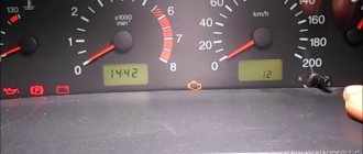
Instrument needles are jumping
It often happens that they simply start jumping on a scale from minimum to maximum. Typically, the cause of such a malfunction is a poor connection between the contact and ground. Its wire coming from the shield is fixed on the partition separating the engine compartment from the passenger compartment.
You can find it by removing the radio from its socket. But if an alarm was installed on your car, most likely, the fastening of this wire was moved to a more convenient place for greater convenience. Usually, experts move it behind the interior trim, not far from the driver’s left foot.
Car owners can expect the same thing after installing a radio. At the moment of fixing its negative cable, perhaps the ground wire of the shield was poorly wrapped. As a result of this oversight, under the influence of vibrations transmitted to the car body, the cable could become loose.
This happens very often, and for a long time car owners cannot understand why the dashboard on the VAZ-2010 does not work. It is worth saying that even specialists often wrap the mass wire poorly due to the fact that doing so is not entirely convenient.
If the fastening of this cable turns out to be of good quality, it is worth checking the shield itself. To do this, it must be removed from the place of fixation so that you do not have to disconnect the wires going to the pads.
You need to check the mass cable on the white block X1, going to the first contact. In addition, it is worth checking the voltage on pins 9, 6 and 10 - it should be at least 12 volts
In addition, be sure to pay attention to the condition of the tracks at the back of the panel, along which impulses are transmitted to consumers
Possible causes of malfunction of the on-board computer and the main ways to eliminate them
One of the most common reasons is a lack of communication with the controller or line-K. What does the current error indicate and what needs to be done:
- the appearance of this error directly indicates a broken contact, or a poor connection of line-K with the additional block;
- The first thing you need to do is check line K according to the diagram;
- in most cases, the cause of this malfunction is a contact break between line-K and the diagnostic block.
Failure in temperature sensor readings
Occasionally, due to exposure to extremely low temperatures, off-board temperature sensors may fail. Typically, in this case, there are two options:
- breakage of the corresponding contacts;
- failure of the sensor itself or partial loss of functionality.
Note. Sometimes, if there is a practical need, you can install two on-board computers in a car at once, each of which will confidently occupy its own niche.
The instructions for installing the on-board computer with your own hands are quite clear and allow you to easily do everything yourself. However, if the choice is made to do everything yourself, then the use of photo and video materials is a prerequisite. Since a car’s on-board computer costs a very substantial amount of money, the cost of installation at a car service center is quite significant. Therefore, it will be better if you do the replacement yourself, especially since it does not present any practical difficulties.
What can a bortovik do?
Depending on the model, the functionality of the on-board devices may vary significantly. The simplest ones display information about the outside temperature, driving speed, current and average fuel consumption, the distance that can be driven with the fuel remaining in the tank and some other data. In addition, the on-board computer displays the voltage in the on-board network and the vehicle’s engine operating parameters, namely crankshaft speed, air flow and throttle opening angle. This data helps identify problems earlier.
Thus, there is no need to go to diagnostics and connect an error scanner every time the “Check Engine” indicator lights up on the dashboard. In addition, it can reset errors stored in the electronic engine control unit and completely erase its memory. This is necessary in cases where, even after troubleshooting, the motor continues to operate incorrectly due to errors.
Another equally useful function that not all on-board vehicles have is warming up the spark plugs. This procedure takes about a minute and in severe frost makes it much easier to start the engine, because in addition to heating up the spark plugs, it starts a chemical reaction in the battery, which also “warms up” in this way.
There are other functions that the on-board computer can perform, which are not so necessary, but sometimes useful. Thus, some models remind you that it is necessary to carry out vehicle maintenance or renew your insurance. Many on-board devices can work as an alarm clock.
Installing an on-board computer allows you to solve another problem that is inherent not only to VAZ-2110 cars, but also to many other models of the Volzhsky Automobile Plant, namely, a fuel level sensor that often fails or simply gives incorrect readings. The on-board computer is usually configured in such a way that either it transmits information about the amount of fuel in the tank from the fuel level sensor, or it is calibrated manually, then the device independently calculates the remaining fuel. The only thing that is required from the driver in the future is to manually set the amount of gasoline after each refueling.
How to reflash the on-board computer?
- A flashing program (for example, BootLoader.exe) is installed on the PC or laptop.
- Next, you should connect the bookmaker to your personal computer.
- The next step is to connect the power.
- In the flashing utility, you need to set the value of the port to which the COM1 data cable is connected.
- If the previous step is completed correctly, the “upload file” button will appear, and after its activation, a window will open in which you need to select a firmware file in the “hex” format.
- Next, all that remains is to press the “Start ISP” button, and use the on/off key to restart the on-board computer. A loading indicator will be available on the PC display.
- After the download of the updated software is completed, the message “download complete” will be displayed on the screen, and the system will also prompt you to start the controller. After confirming the operation, it is necessary to check the functioning of the new BC firmware.
On-board computers are divided into two types
1. Universal - they are suitable for any model. They are most often installed on the roof next to the rearview mirror or on the windshield.
2. Made specifically for certain car models.
In truth, a BC cannot be called an essential item - many owners get by just fine without it.
On the other hand, just imagine what opportunities it gives you.
For example, you need parking sensors, you want to install a DVD, a navigator or something else. For all this you need a separate place. And all of this needs to be managed separately.
If you have an on-board computer on a VAZ 2112, then you will control all devices through it, and they will be connected to it. That is, you save your time and space in the car. Then you may have a question...
Nuances of setting up a bookmaker
After connecting the bookmaker, it needs to be configured. To set up a bookmaker, you need to perform the following series of actions:
- Turn on the vehicle ignition and start the engine.
- Activate settings mode.
- Select the type of electronic unit.
- Select fuel consumption mode.
- Select the indicators that will be displayed on the device screen and adjust the backlight brightness.
- The final, important stage of setup will be determining the conditions for turning on the fan to cool the motor. To set the condition for turning on the “cooler”, you need to specify the engine temperature at which the motor requires cooling.
Selection of diagnostic equipment
Demand creates supply. Online stores are full of advertisements for diagnostic devices that check all kinds of car brands of different years of production. Adapters that satisfy a wide range of untrained users are considered. The buyer makes the choice. Some car enthusiasts want to perform periodic monitoring, maintain the operating condition of the vehicle, and use a laptop or tablet. Others like to be an airline pilot, constantly monitoring changes in dozens of parameters on a smartphone by connecting a test device permanently. The diagnostic devices produced will satisfy various wishes.
VAZ car owners should pay attention to devices designed to test VAG Group vehicles (48 automobile manufacturing enterprises producing branded cars in 21 countries around the world). In an effort to enter the world market, VAZ developers focused on electronic units with the logic for constructing tires from the VAG concern. The scanner must support the required protocol. Vehicles manufactured before 2007 are checked using the K-Line bus. New cars operate via a CAN bus; the K-Line bus is not provided on the connector.
Setting an alarm
- Press button 4 in Alarm mode.
- Use buttons 5, 6 to set the desired hour value.
- Press button 4. Use buttons 5, 6 to set the desired minute value.
- Press button 4 to complete the alarm setting.
- In the “Current time” mode, the alarm symbol will light up (the alarm is on).
* If the counter of any of the accumulated parameters (“Travel time”, “Travel time with stops”, “Total consumption”, “Trip mileage”) overflows, all accumulated ones, as well as calculated ones (“Average fuel consumption”, “Forecast”) are reset mileage on remaining fuel", "Average speed") parameters, with the appearance of a two-tone sound signal.
Turning off the alarm
- Press button 4 in Alarm mode.
- Press button 1 to turn off the alarm. “—.—” will appear in the digital digits, and in the “Current time” mode the alarm symbol will not light up (the alarm is turned off).
Adjusting the brightness of the indicator backlight
When the side lights are on, the illumination level is adjusted using the instrument scale illumination regulator. When the side lights are turned off, the backlight level is adjusted by software: