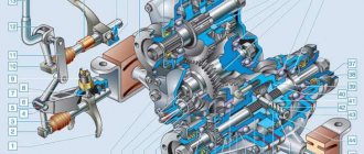
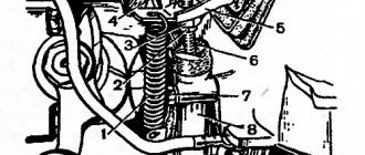
Transfer case installation diagram
| 1 – stud for fastening the flanges of the intermediate cardan shaft and the drive shaft of the transfer case; 2– adjusting shims; | 3– nuts securing the transfer case to the body; 4– nuts securing the transfer case suspension brackets to the axles |
EXECUTION ORDER
1. Make sure that the engine mount mounts are correctly installed in the brackets (the centering washers of the front engine mount mounts must fit into the corresponding holes in the side brackets) and that the transfer case supports fit snugly to the bottom of the body. If necessary, straighten the surface of the body under the supports. 2. Install the transfer case on the vehicle without fully tightening bolts 4 and 5 of the transfer case suspension brackets (see Fig. Transfer case installation diagram). 3. Moving the transfer case lengthwise and crosswise, as well as in the vertical direction, find a position in which the flanges of the transfer case drive shaft and the intermediate driveshaft are at the same level, parallel, and the gap between them is minimal. The transfer case shafts must be located parallel to the bottom of the body. 4. Having installed the previously removed adjusting shims under the suspension brackets (supports), fully tighten the nuts securing the transfer case suspension brackets. 5. Attach the front and rear propeller shafts to the transfer case shafts; Connect the flexible shaft to the speedometer drive and the wires to the differential lock warning lamp sensor. 6. When replacing the transfer case, as well as when the rear engine mount “settles”, causing vibration of the transfer case, it is necessary to select and install a new thickness of gaskets 5 (see figure from paragraph 8).
Procedure for selecting shims
1. Make sure that the engine mounts are installed correctly in the brackets (see subsection 2.2). 2. Separate the flanges of the transfer case drive shaft and the driveshaft intermediate shaft. 3. Loosen the nuts securing the transfer case supports to the body, remove the adjusting shims and, moving the transfer case along and across the body, as well as in the vertical direction, find its position in which the disconnected flanges are at the same level, parallel and the gap between them is minimal , and the transfer case shafts are located parallel to the bottom of the body. 4. Fill the resulting gap between the body floor and the supports with the required number of gaskets. 5. Align the centering flanges without creating tension in the transfer case and engine supports and, holding the transfer case in this position, tighten the previously loosened nuts securing the transfer case supports. 6. Insert and secure the transfer case and intermediate shaft flange bolts; if the bolts pass freely into the flange holes, then the alignment is carried out correctly, otherwise repeat the operations to align the flanges.
Many people are interested in how to center the transfer case on the Niva. There are enough reasons for such interest. The transfer case mounting on this VAZ creation leaves much to be desired. Of course, the transfer case does not fall on the road, but it can cause quite a lot of inconvenience. Therefore, drivers strive to learn how to solve alignment problems on their own, without the participation of a car service center. In fact, centering is a fairly simple job. You just need to know the correct algorithm of actions. Otherwise, there shouldn’t be any difficulties; after all, the Niva is a simple car and is designed for garage service.
How to center the transfer case on a Niva? First you need to decide why this is being done. To understand this, you need to understand the technical features of this unit. The transfer case is attached to the body using special brackets. It is this fastening that is to blame for the misalignment. For some reason, domestic engineers did not realize that a simple threaded fastener could become loose. This causes the box to shift relative to the gearbox. This causes vibration, which is the first sign that the transfer case needs to be centered.
Centering method
To carry out this work you will need a lift, although with some skill you can get by with simple supports. First you need to prepare the car. If there is a lift, it is raised up. If supports are used, the corners of the machine are jacked up one by one and it is placed on them. Please note that all supports must be stable, otherwise the work will be unsafe. You should also prepare the tool in advance. If there are no plans to simultaneously replace other parts, then it is quite possible to get by with a ratchet and a “13” head. During operation, an assistant must be in the cabin.
Eliminating prerequisites
The misalignment of the transfer case occurs due to an undeveloped design. Therefore, many craftsmen strive to modify the fastening so as not to bother with alignment once a year. A special frame is used for this. In recent years, it can be purchased in stores, but you can also make it yourself.
The advantages of this modification are the following:
- The transfer case is mounted on the rigid base of the subframe. The attachment to the body is made through a subframe, this allows to reduce the level of vibration transmitted to the body;
- It plays the role of a kind of protection for the crankcase;
- Also worth mentioning is adding additional rigidity to the side members.
- Among the disadvantages, we can mention a slight decrease in clearance. Although, in light of the advantages, this does not play a special role.
To assemble the subframe you will need a square pipe. Some people use a corner, but in this case the structure will be less durable. The support plates are made of sheet steel.
Before assembly, you should cut off the old transfer case mounting bolts. Now it will be installed on the subframe. The pipe is cut to size and the frame is welded. After that, holes are drilled in the crossbars for fastening the transfer case. It is important not to make a mistake with the sizes. The next step will be assembling the mount to the body. Sheet steel support plates are welded to the subframe. Holes are drilled in it. After fitting, you need to drill holes in the floor of the car.
M12 bolts should be used for fastening
, as well as thick washers. After installing the subframe, do not forget to treat it with an anti-corrosion compound. This will increase the service life of the part. This is how, through simple manipulations, you can get rid of one of Niva’s sores.
Conclusion
. Even great cars have flaws. The domestic SUV Niva is no exception. During active use, vibrations emanating from the transmission may occur. That’s when the question arises of how to center the transfer case on the Niva. In fact, this work is not difficult, but there are some nuances that are better to know before starting work. Some people, knowing this feature of this car, install a subframe, this can significantly reduce the noise of the transmission.
The Niva family of cars differs from VAZ passenger cars in permanent all-wheel drive - they have two drive axles. In total, the VAZ SUV has three differentials in its transmission - one for each axle and another center differential.
The Niva transfer case is designed to distribute traction forces between axles, and operates on the principle of a 2-speed gearbox.
Transfer case Niva 21213
Model VAZ-21213 is an all-terrain passenger car with permanent all-wheel drive and differential lock. Brand 21213 is a restyled version of the first VAZ SUV, VAZ-2121. RK Niva 21213 has three gears:
- the first - with a gear ratio of 1.2;
- the second, lowered – with the number 2.135;
- neutral
21213 is equipped with 4-speed and 5-speed gearboxes, and when the first speed of the transfer case is turned on, the car operates in standard mode, the gear ratios in the transmission are from 5-speed. The checkpoints are as follows:
When you turn on the second position of the transfer case lever (reverse position), the gear ratios change (lower):
On ordinary roads, the transfer case is always in first gear, the transfer case control lever (reduction gear) is pushed forward. The neutral gear of the RK disconnects the transmission, and in this position the car does not drive; there is also a neutral in the gearbox.
Motorists often ask the question: why is neutral gear needed in a transfer case? The neutral is used when connecting additional units to the transmission, for example, a mechanical winch; in this case, a power take-off must also be installed.
Understanding the terminology
Let's start by diving into the materiel. Transfer case (TC) is a separate unit of an all-wheel drive vehicle, which provides multi-mode power distribution from the engine to the front and rear axles.
Externally, this is a mechanism located under the bottom of the car, in the body of which a multiplier (divider) is placed in series to obtain an intermediate gear ratio in the transmission and a splitter of one power flow into two. It is with the help of this device and its controls (levers) that go into the vehicle interior that the LADA 4×4 driver selects the all-wheel drive operating mode.
The RK directly connects the front driveshaft and the intermediate shaft (shaft) with the vibration damper to the vehicle’s gearbox. As is probably already clear from the description, this element is connected to the rear axle of the car via a rear propeller shaft.
Transfer case 2123 (2-row bearing) Chevrolet Niva Art. 21230-1800020-0116500.00-+ Buy
Transfer case 2123 Chevrolet Niva Art. 21230-1800020-0114500.00-+ Buy
Transfer case (2-row bearing) 21213 Art. 21213-1800020-0115000.00-+ Buy
Malfunctions of VAZ transfer cases
The transfer case on the Niva is a fairly reliable unit; problems with repairs in the mechanism itself arise mainly due to insufficient oil level in the valve - if for some reason the oil leaks out, intensive wear of all parts occurs. Among the frequently occurring malfunctions are:
- vibration in the body at various speeds when the car is moving;
- vibration when the vehicle starts moving;
- noise in the transfer case when the car is slipping or turning;
- difficult upshift or downshift, difficult engagement of the lock.
We study problems and repair methods.
Any car owner definitely doesn’t need to be told why howling and humming are bad. Vibration of the transfer case on a Niva at low speed is quite common. The driver, of course, gradually gets used to many extraneous sounds in the car, but the noise level is high enough to make it impossible to carry on a conversation with passengers while traveling. Due to excessive noise pollution, you will inevitably have to deal with the problem.
Sources
- https://motorltd.ru/snyatie-i-tsentrirovanie-razdatochnoy-korobki-vaz/
- https://sv-parts.ru/blog/detail/vibracii-voi-razdatki-niva-kak-ubrat/
- https://AutoFlit.ru/2260-kak-otcentrovat-razdatku-na-nive-sposob-dlya-korotysha-i-shevrole.html
- https://NewNiva.ru/samodelka-razdatka-niva.html
- https://avto-idea.ru/remont/remont-razdatki-na-nive-21213-kak-ottsentrovat/
- https://avtomechanic.ru/niva-vaz-21213/transmisiya-vaz-21213/kak-ustranit-vibratsiyu-razdatochnoj-korobki-vaz-21213
- https://zen.yandex.ru/media/id/5f2ae91f66ca0e557c7aba7d/nadoel-voi-razdatki-na-nive-rasskazyvaiu-kak-ia-ot-nego-izbavilsia-5f2c55c38fa8d55d29d4d8dc
- https://niva-fr.ru/tyuning-osnovnaya-statya/vibratsii/
- https://NewNiva.ru/kak-ustranit-vibratsiyu-na-nive-21214.html
Vibration
Vibration in the body is the main “disease” of the Niva; it often occurs due to improper alignment of the transfer case. Most often, vibration occurs on VAZ 21213/21214 cars, since the transfer case is mounted only on two supports on the sides of the body; on the Chevrolet Niva, the transfer case is already installed on three supports. But before you start adjusting the position of the transfer case, you should check the condition of other parts of the chassis - vibration can occur for other reasons:
- driveshafts are poorly secured;
- wheels are not balanced;
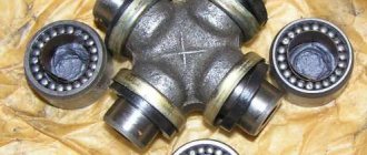
- there is play in the cardan crosspieces (vibration is especially affected by play in the rear driveshaft crosspieces);
- The vibration comes from the engine itself.
Vibration when starting off on a Niva can also occur for the following reasons:
- the mounting supports of the transfer case have become loose;
- The rubber on the RK supports themselves broke.
Removing the howl and hum
We will assume that we have dealt with the vibration, but an equally significant problem remains - how to remove the howling of the transfer case on the Niva. Vibrations of the mechanism are not always the only reason for the appearance of extraneous irritating sounds. And the characteristic noise of the transfer case, alas, is one of the “trademark” shortcomings of one of the best domestic SUVs.
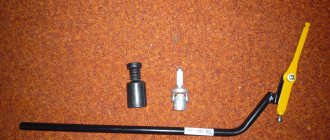
- The first thing you should pay attention to is the levers. It is better to immediately replace them with silent ones - with anti-resonance bushings inside. They won’t eliminate all the noise, but they will definitely extinguish some of it.
Silent transfer case levers NIVA 2121 black Art. SV-21-18040401400.00-+ Buy
- The result will be even better if you install a small-module transfer case - with front and rear covers equipped with double-row bearings. In 2010, AVTOVAZ introduced new double-row bearings for output shafts in order to get rid of backlash and runout, as well as extend the life of the seals and, in general, increase the reliability of the mechanism. Here logic is man’s friend: less shaking and hesitation means higher service life and reliability.
Transfer case (2-row bearing) 21213 Art. 21213-1800020-0115000.00-+ Buy
Transfer case alignment
Correct installation of the transfer case can be done in several ways. Most often in auto repair shops, repairmen use the following method:
- hang the car on a lift;
- loosen the transfer case;
- start the engine;
- engage the gear and accelerate the car according to the speedometer to the speed at which vibration occurs (often it occurs at speeds from 40 to 80 km/h);
- without using the brakes, reduce the engine speed, then turn off the ignition.
Eliminate vibration with additional fasteners
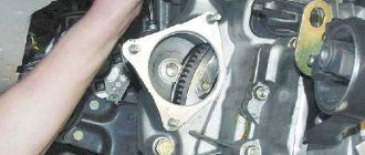
Installing the third support of the transfer case on VAZ 21213/21214 vehicles allows you to reduce the level of vibration of the transfer case; with this support it is easier to center the transfer case. The part can be purchased at auto stores or made yourself. The finished product comes with three long studs (for model 2121); to install the third support on this machine, you will need to unscrew the short studs from the transfer case housing and install new studs from the kit. We carry out repairs as follows:
- dismantle the front passenger seat in the cabin;
- remove the floor tunnel lining;
- in the cabin we move aside the carpet covering the body amplifier (in front of the handbrake lever);
- remove the transfer case (alternatively, you can simply hang it up, but removing the third support makes it easier to install);
- We attach the bracket of the new support to the body of the RC;
- we install the transfer case in place, center it in the optimal position, and fasten the side supports;
- we combine the third support with the body, drill two holes in the bottom;
- Using washers, bolts and nuts (from the kit) we attach the support to the bottom of the body.
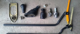
Vibration is eliminated more effectively by installing a subframe under the transfer case. You can also make such a device yourself or buy a finished product at a car store.
In order to install the subframe, the transfer case must be removed. It is more convenient to carry out such work in a pit; we carry out repairs as follows:
- leave the car in neutral gear;
- disconnect the propeller shaft from the transfer case, it is advisable to mark the driveshaft flange and the drive shaft so that during installation, align the driveshaft according to the marks - this way, the occurrence of unnecessary vibrations is eliminated;
- dismantle the muffler mounting bracket;
- remove the gearbox traverse;
- jack up the transfer case, remove the side fastenings of the transfer case;
- We treat the places where the subframe fits to the body with Movil;
- place the subframe on the gearbox studs;
- we mark the attachment points of the subframe on the side members, drill holes, attach bolts to the body;
- we tighten all fastenings, except for the transfer case supports themselves;
- we perform alignment of the steering wheel;
- Finally tighten the transfer case supports.
It should be noted that installing an additional support or subframe on the steering wheel does not always lead to the desired effect; in some cases, vibration only increases.
Removing the Niva transfer case
To repair the transfer case on a VAZ 21213 (21214), the unit must first be removed. We carry out removal in the following order:
- in the cabin we dismantle the plastic lining of the gearbox and gearbox levers;
- unscrew the knobs of the transfer case shift levers, remove the casing under them;
- disconnect the speedometer cable, for RK 21214 you will need to additionally disconnect the speed sensor;
- we unscrew the bolts with nuts securing the elastic coupling of the front and rear propeller shafts; in order to remove the bolts, the cardan shafts must be turned - they are removed one at a time in one specific position of the shaft;
- We install a jack (or other support) under the transfer case and mark the places where the side supports of the RC were attached. This is done in order to minimize the alignment of the transfer case during installation;
- unscrew the 4 nuts securing the gearbox to the gearbox;
- unscrew the 4 fastenings of the RC supports to the car body;
- Now all that remains is to dismantle the transfer case.
Disassembly
1 — front axle drive housing; 2 — crankcase cover; 3 — speedometer drive housing fig. 3-39fig. 3-38
rice. 3-38fig. 3-39
1- intermediate shaft; 2 - drive shaft; 3 — differential; 4 - front cover
1 - flange; 2 — oil seal; 3 — thrust ring of the bearing, 4 — front bearing; 5 - drive shaft; 6—high gear; 7 — hub; 8 - coupling; 9 — low gear; 10 — bushing: 11 — rear bearing; 12 — bearing installation ring; 13 — intermediate shaft bearing; 14 - intermediate shaft
- remove the lock ring 1 (Fig. 3-45) and spring washer 2 of the front bearing;
- remove the rear and front bearings from the differential housing (Fig. 3-46), using a universal puller and stop 67.7853.9559;
- by turning the bolts of the differential housing, separate the housing;
- remove the differential driven gear;
- remove retaining rings 8 (Fig. 3-45) and spring washer 14, then press out the pinion axis and remove the satellites and drive axle drive gears with support washers.
Also interesting: Adjusting VAZ 2114 and 2115 headlights: tips and tricks
1 - retaining ring; 2 - spring washer; 3 - bearing mounting ring; 4 — differential housing bearings; 5 — driven gear; 6 - front differential housing; 7 — front axle drive gear; 8 — retaining ring of the satellite axis; 9 — satellite; 10 — rear differential housing; 11, 15 — support washer; 12 — rear axle drive gear; 13 — satellite axis; 14 - spring washer
We recommend: Chip tuning: high-quality car acceleration and saving resources
1 — puller A.40005/1/6; 2 — stop 67.7853.9559; 3 - bearing
- the axial clearance of each axle drive gear should be 0-0.10 mm, and the moment of resistance to rotation of the gears should not exceed 14.7 N m (1.5 kgf m). If the gap is increased, replace the support washers with others of greater thickness; if the specified gap cannot be obtained when installing support washers of the greatest thickness, replace the gears with new ones due to their excessive wear;
- The drive and intermediate shafts are installed in the transfer case housing simultaneously (see Fig. 3-47);
- Press the bearings onto the differential housing using mandrel 67.7853.9558 (see Fig. 3-48);
- Before installation in covers and crankcases, lubricate the working surfaces of the oil seals with LITOL-24 grease;
- Tighten threaded connections to the torques specified in Appendix 2;
- when compressing the transfer case shaft nuts, use mandrel 67.7820.9520 (see Fig. 3-49).
1 - intermediate shaft; 2 - drive shaft
1 — mandrel 67.7853.9558
1 — mandrel 67.7820.9520; 2 - flange retainer