An electromagnetic device called a Hall sensor (hereinafter referred to as Hall sensor) is used in many devices and mechanisms. But its greatest application was found in the automotive industry. In almost all models of the domestic automobile industry (VAZ 2106, 2107, 2108, etc.), the non-contact ignition system for a gasoline engine is controlled by this sensor. Accordingly, when it fails, serious problems arise with the operation of the engine. In order not to make mistakes when diagnosing, it is necessary to understand the principle of operation of the sensor, know its design and testing methods.
Design and principle of operation
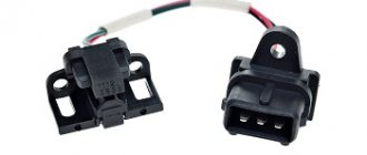
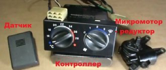
The controller design consists of the following parts:
- magnet;
- rotor;
- chip;
- plastic housing;
- conclusions;
- magnetic circuits.
The sensor operates based on the Hall effect. The principle of operation of the element is as follows:
- The rotor has four teeth that rotate while the engine is running.
- Pulses are constantly read.
- The received information in the form of a signal is sent to the switch.
- The pulse arrives at the installed coil.
- An increased voltage of 22–25 kV is supplied to the spark plugs.
The type of functioning is not complicated.
Hall sensor for VAZ 2107
The Hall sensor is one of the main devices in the contactless ignition system of gasoline engines. If a problem occurs with this part, the operation of the engine is disrupted. In order to be able to diagnose the problem in a timely manner, it is important to know and understand how the Hall sensor (HL) works and, in particular, on the VAZ 2107, how to determine the malfunction and replace the device. All these points are worth dwelling on in more detail.
The Hall sensor is the main element of the contactless ignition system of a gasoline engine
Purpose of the sensor
A number of electronic car systems are equipped with sensors that send a signal to the corresponding unit responsible for the operation of the power unit to change certain parameters. The contactless ignition system of the VAZ 2107 also has a device called a Hall sensor (HL). Its purpose is to determine the position angle of the crankshaft and camshaft of the power unit. The sensor is installed not only on modern, but also on old cars, for example, VAZ 2108/09. According to the readings of the element, current is supplied to the spark plugs.
Operating principle of the device
The operation of a DC is based on the effect of increasing voltage in the cross section of a conductor placed in a magnetic field. At the moment when a spark should appear, a change in the electromotive force occurs; a signal from the distributor is sent to the switch and spark plugs. If we consider the Hall sensor, which is used today in contactless ignition systems, it is a device for detecting changes in the magnetic field during camshaft operation. To trigger the element, a certain value of magnetic induction is required.
The sensor works as follows: there is a special crown-type plate on the distributor axis. Its special feature is the slots, the number of which corresponds to the number of engine cylinders. The sensor design also includes a permanent magnet. As soon as the ignition distributor shaft begins to rotate, the driven plate intersects with the sensor space, which leads to the generation of a pulse that is transmitted to the ignition coil. This impulse is converted and causes a spark to form on the spark plugs, as a result of which the air-fuel mixture is ignited.
The principle of operation of the Hall element: 1 - magnet; 2 - plate of semiconductor material
As the engine speed increases, the frequency of pulses coming from the DC increases, which determines the normal operation of the power unit. Despite the fact that the phenomenon considered was discovered long before production cars appeared, it is nevertheless used in automotive production today. The sensor is a fairly reliable device, the breakdown of which does not occur very often.
Video: Hall sensor operation
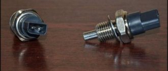
The Hall sensor has three contacts:
- weight;
- plus power (about 6 V);
- communication with the ignition system switch.
Where is the DH on the VAZ 2107
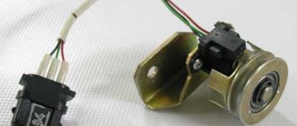
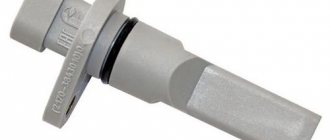
If you are the owner of a VAZ “Seven” with contactless ignition, then it will not be superfluous to know where the Hall sensor is located. Finding the ignition distributor is not difficult, but the sensor itself is located under its cover. To access the DC, you need to remove two latches and remove the distributor cover, after which you can see the sensor itself.
The Hall sensor on the VAZ 2107 is located in the engine compartment under the distributor cover
Connection diagram
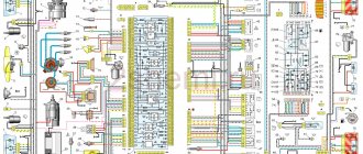
The Hall sensor has a direct connection with the switch and is connected according to the diagram shown in the figure.
The Hall sensor has a simple connection diagram: the signal from the device is supplied to the switch, and then to the ignition coil
The switch itself performs the following functions:
- amplifies the pulses to 12 V and transmits them to the ignition coil;
- receives a signal from the DC in the form of an impulse.
In simple words, the switch is a regular amplifier, which is designed in a similar way to an assembly based on field-effect transistors. Despite the simplicity of the circuit, the device is easier to purchase than to make yourself. The main thing is that the Hall sensor and the switch on the VAZ 2107 are correctly installed and connected. Otherwise, the sensor will not work properly.
The switch is designed to amplify the pulses received by it from the Hall sensor
Connection diagram
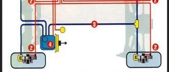
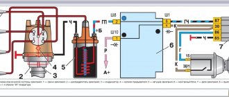
The figure shows a basic electrical drawing for the VAZ 2108 and 2109 with pinout of contacts.
The ignition system operates as follows:
- The wire transmits voltage to the sensor from the switch through the red wire.
- A magnet creates a field.
- An impulse is supplied to the switch through the green wire.
Using a Hall element, the voltage directed to the high-voltage coil is regulated.
Another diagnostic method
Before checking the Hall sensor on the VAZ-2109, you will need to make preparations.
But at the same time you will certainly determine the integrity of the device. Execution procedure:
- Connect the central terminal of the ignition coil to the spark plug.
- Connect the spark plug body to the power supply negative (ground).
- Remove the Hall sensor.
- Turn on the ignition. The block with wires must be connected to the sensor.
- Use a screwdriver or any metal (magnetic) object near the active part of the device. If a spark appears, then the sensor is working. If not, it needs to be replaced.
However, if the operation of the sensor is unstable, this method may not help - try installing a known good one.
Symptoms of a problem
Over time, the device becomes unusable. This can be recognized by the following signs:
- the engine runs poorly or stalls;
- the engine does not idle;
- car detonation is observed;
- While driving, the engine turns itself off.
Problems are not always serious. Sometimes the cause is simple oxidation of the contacts. It is enough to move them to restore engine operation. Such symptoms appear due to weakening of the sensor fasteners. To do this, it needs to be tightened. It happens that the reason lies in a short circuit in the wiring.
How to check
If you suspect a sensor malfunction, you can diagnose it as follows:
- Using a working element. The power is disconnected from the main sensor and connected to a new device. Then the central ignition wire is removed and placed on a metal surface. This is done to visually record the spark. The ignition turns on. To simulate the operation of the screen, a thin metal object is moved near the magnet. If a spark appears noticeably, it means that the original sensor was faulty.
- Using a multimeter. First, it is switched to voltmeter operating mode. The meter wires are connected to the element. When you move a metal object inside the sensor, the operation of the screen will be simulated. If the device shows a voltage change ranging from 0.4 V to 11 V, then the element is working.
- By creating a simulation of a new sensor. Power is disconnected from the element. The central wire of the distributor is removed and placed on ground to observe the spark. At the next stage, contacts “3” and “6” are closed and a spark is observed. A sensor malfunction is confirmed if it slips.
If such a check indicates a breakdown, then the element must be discarded and a new one installed.
Reasons for failure of diesel generators
Below are the most common factors for Hall sensor failure:
- Presence of contamination. A common cause of breakdown is simple dirt. When it appears, the controller will signal this - the car begins to act up.
- The spark is gone. It is necessary to check the wiring and terminals for the presence and quality of contact. Oxidation of at least one of the three terminals can lead to a circuit break. In addition, a simple bend or break in the wire may occur - this may be caused by the displacement of the DC pad by the vacuum ignition corrector. To avoid this, the wiring must be secured so that when displaced it bends into a loop.
- Wiring failure. If the high-voltage wiring in the car is heavily worn out, if it runs close to the sensor wires, there is a possibility of a high-voltage breakdown. This often happens when the air humidity is high or when you accidentally drive into a deep puddle.
It is better to place the wires from the sensor away from the rest of the car's wiring. You can also avoid this problem by regularly replacing all electrical wiring once every two to three years. In addition, the sensor may fail due to overcharging of the battery generator if the controller received an excessive load and any element burned out at the switch contact.
Replacement
When the check shows a malfunction of the sensor, then for removal you need to prepare a 10 mm wrench and a screwdriver. Procedure steps:
- Power is turned off from the device.
- The distributor is removed from the car.
- The device is placed on a workbench and the cover is removed.
- Carefully remove the boot with the slider.
- The plug screw is unscrewed.
- Remove the support plate screws.
- The vacuum corrector is dismantled. To do this, unscrew 2 screws.
- All wires are available.
- The sensor is removed along with the support plate.
- A new element is installed and installation is carried out in the reverse order.
During the replacement process, the entire internal space of the distributor must be thoroughly cleaned of dirt. As with flushing the carburetor, acetone is used for this.
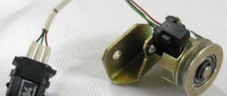
Where installed
The hall sensor is located inside the ignition distributor (distributor). The magnetic element is secured to the support plate, under the slider boot, with two screws. 3 wires come from it: red, green and black (positive, pulse, negative) and are connected to the block, which is secured with 1 screw at the exit from the distributor body. The pinout of the wires is in exactly this order.
Prices
For VAZ 2108–2109, the original number of the Hall device is product with article number 21080-3706800-00. If it is not available, pay attention to analogues. Possible options are presented in the table.
| vendor code | Manufacturer organization | Price in rubles |
| 21080-3706800-00 (original) | LADA | 590 |
| 21080370680082 (analog) | AVTOVAZ | 240 |
| GLSS133 (analog) | GALLANT | 230 |
| 21080370680000 (analog) | AUTO ELECTRONICS | 195 |
| 21080370680001 (analog) | AVTOVAZ | 190 |
| RK02008 (analog) | REMCOM | 150 |
The presented analogues are high-quality products that can be installed on a car.