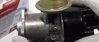
Almost all classic models are traditionally equipped with a standard contact-type ignition system (KSZ). An exception is 21065, which uses a non-contact transistor circuit in which an interruption of the primary winding power circuit is realized using a breaker mounted in the distributor. Below we will consider in more detail how the contact ignition system of the VAZ-2106 is designed and works.
Difference between factory device and electronic type system
Any ignition mechanism implies the same device. The electronic ignition connection diagram for the VAZ 2106 provides for the presence of many common elements. These are spark plugs, armored wires, a distribution device, a coil. The presence of candles is mandatory, because without them a spark will not form.
Armored wires are used to connect high-voltage parts. They are cords made of special fibers along which a power charge moves.
The ignition distribution device (distributor) is different for many cars. Its functions can be understood based on its name. The installation of contactless ignition for the VAZ 2106 is not complete without such an element.
The coil has the property of increasing the voltage supplied to the winding surface. Comparing the contact and electronic ignition of the VAZ 2106, it follows that the first is characterized by a central axis, which carries out its movement thanks to the drive mechanism from the oil pump. There is a small cam on the axis that participates in the operation of the contact block. This part also serves to transfer the power charge to the coil. Transmitting a large current requires the operation of the entire contact group, which complicates the process and leads to many problems.
The electronic ignition system of the VAZ 2106 requires a Hall sensor. This component serves as a contact breaker and has no direct contact. It also creates a weak impulse, which will not be able to ignite the upper winding surface of the coil. This device enhances the push and delivers at the right time.
What is BSZ and how does it work?
To successfully install and configure contactless ignition, it is advisable to understand the operating principle of the system, which consists of the following elements:
- Main ignition distributor (otherwise known as distributor). Inside it is installed a photoelectric Hall sensor, a vacuum drive for adjusting the advance angle and a so-called slider with a moving contact.
- A coil that produces a high voltage pulse. It has 2 windings: a primary winding, consisting of a small number of turns of thick wire, and a secondary winding, wound with a thin wire with a large number of turns.
- The electronic unit is a switch equipped with an aluminum cooling radiator. The latter plays the role of a fastening element.
- Spark plugs connected by high-voltage wires to the distributor.
- Wires for connecting elements to each other.
This is what the ignition system of a classic Zhiguli looks like
For reference. In the standard outdated VAZ 2106 systems, there was a contact group inside the distributor instead of a Hall sensor, and there was no switch at all.
BSZ operation scheme
The first contact of the coil is connected through the ignition switch relay to the generator, and the second to the control unit. Also, a high-voltage wire with a large cross-section goes from it to the distributor. There are 2 bundles of wires coming out of the distributor, connecting it to the switch and spark plugs. The system operates according to the following algorithm:
- After turning on the ignition by turning the key in the lock, a voltage of 12 V is applied to the primary winding of the coil, which creates an electromagnetic field.
- When the crankshaft rotates and one of the pistons reaches top dead center (TDC), the photoelectric sensor sends a signal to the switch, which briefly breaks the connection between the coil and the voltage source - the generator or battery.
- During a circuit break, a voltage pulse of 20 to 24 kV is generated in the secondary winding of the coil, transmitted through a large cross-section wire to the distributor slider.
- The movable contact of the slider directs the impulse to the spark plug where the piston reached TDC. A powerful spark jumps between its contacts, igniting the mixture of fuel and air in the combustion chamber.
- The distributor shaft is driven by a gear transmission connected to the crankshaft. When the next piston moves to TDC, the shaft rotates and the moving contact connects to another spark plug, and the Hall sensor sends the next signal and the sparking cycle is repeated.
Reference. In older systems, the circuit was broken mechanically using a cam on the distributor shaft, pressing on the contact group.
Disadvantages of the conventional ignition mechanism
Today, the contactless ignition system of the VAZ 2106 is used on many cars of this series. The contact mechanism is not available on newly produced vehicles. After all, this is due to the following shortcomings in the operation of the car and its parts :
- The occurrence of such a phenomenon as a spark jumping, which was reflected in their burning;
- Frequent cleaning;
- Short period of operation of the contact group;
- Frequent wear of the bearing on which the contacts are located, which led to instability of the engine;
- Stretching the balancers.
These shortcomings do not appear immediately, but one by one. Therefore, the owner of the “six” may be in constant repair. The structural structure of the contact group affects the charge power, reducing this value. As a result, the power unit begins to function worse and fuel consumption increases.
Therefore, car owners begin to think about the question - how to install electronic ignition on a VAZ 2106? And for those who have already done this, the topic is interesting - how to set the electronic ignition?
Electronic ignition kit for VAZ
Advantages of electronic ignition
New contactless mechanisms do not have the negative qualities of the contact group, which affects their durability. The supplied pulse becomes stable and the fuel mixture ignites better. As a result, the installation of contactless ignition of the VAZ 2106 has a number of advantages :
- Reduced fuel consumption;
- Easier car starting at sub-zero air temperatures;
- Stability of engine operation at idle speed;
- Correct adjustment of the system will not require quick reconfiguration;
- Increased service life of spark plugs.
Assessing these advantages, we can say that the electronic ignition circuit of the VAZ 2106 has significant significance, which is felt upon first use. Moreover, many of the shortcomings that appear with a factory ignition will disappear.
BB wires
High-voltage wires, or, as they are also called, spark plug wires, are different from all others installed in the car. The purpose of these wires is to transmit and carry voltage passing through them to the spark plugs and protect other elements of the vehicle from electrical charge.
Spark plug wires provide connection to the ignition coil, distributor and spark plugs
Malfunctions
The appearance of problems with explosive wires is accompanied by the following characteristic signs:
- problematic engine starting due to insufficient voltage on the spark plugs;
- shots at start-up and vibrations during further operation of the engine;
- unstable operation at idle speed;
- periodic engine tripping;
- the appearance of interference during the operation of the radio, which changes when the engine speed changes;
- smell of ozone in the engine compartment.
The main reasons that lead to problems with wires are wear and aging of the insulation. The location of the wires near the engine leads to temperature changes, especially in winter, as a result of which the insulation gradually cracks, moisture, oil, dust, etc. get inside. When cracks reach the conductor, the explosive wire can be pierced to ground, and a spark to the spark plug simply it won't arrive. In addition, wires often fail at the junction of the central conductor and the contact connectors on the spark plugs or ignition coil. To avoid mechanical damage, the wires must be correctly laid and secured with special clamps.
One of the malfunctions of high-voltage wires is a break
How to check
First, you should visually inspect the cables for damage to the insulating layer (cracks, chips, melting)
Attention should also be paid to the contact elements: there should be no traces of oxidation or soot on them. Checking the central core of explosive wires can be done using a conventional digital multimeter
During diagnostics, a broken conductor is identified and the resistance is measured. The procedure consists of the following steps:
- Remove the spark plug wires.
- We set the resistance measurement limit on the multimeter to 3–10 kOhm and connect the wires in series. If the current-carrying wire breaks, there will be no resistance. A working cable should show about 5 kOhm.
I check the wires for damage and spark breakdown as follows: in the dark, I start the engine and open the hood. If a spark strikes ground, it will be clearly visible, especially in wet weather - a spark will jump. After this, the damaged wire can be easily identified. In addition, one day I was faced with a situation where the engine began to misfire. I started checking with the spark plugs, since the wires had been replaced recently, but further diagnostics led to a malfunction in the cable - on one of them there was no contact with the terminal itself connecting the conductor to the spark plug. After contact was restored, the engine started running smoothly.
Video: checking explosive wires
Which ones to put
When choosing and purchasing high-voltage wires, you should pay attention to their markings. There are many manufacturers of the elements in question, but it is better to give preference to the following:
- BERU;
- NGK;
- PARTS-MALL;
- AMD;
- Bremi;
- Tesla Technics.
Today a large selection of spark plug wires is offered, but it is better to give preference to well-known manufacturers
Selection of electronic ignition
The contactless ignition circuit for the VAZ 2106 depends on the type of power unit of the car. Various design features of the distribution element are provided. If a 1.3 liter motor is installed, the distributor has a shortened spindle. If you have a 1.5 L or 1.6 L engine, the distributor spindle is the same for these varieties. The delivery packaging of the contactless mechanism includes the following components:
- Distributor used for ignition distribution. In relation to the volume of the car engine, different articles are distinguished. For a 1.3-liter engine, a device with article number 38.3706-01 is required. Car engines of 1.5 l and 1.6 l should select an element with the designation 38.37061.
- A coil characterized by high voltage. It provides conversion of current not exceeding 12 V. The element serves to multiply low voltage. Can raise up to 20 kV. The article number of the device is 27.3705.
- Electronic type control module - designated 36.3734 or 3620.3734.
Wires are selected as connecting elements. It is possible to use a kit from Niva. The connection diagram for contactless ignition on a VAZ 2106 cannot be made using a contactless kit for a VAZ 2121. The distributor included in the kit for this brand is externally similar to the required device, but their technical indicators are different. Therefore, you should not use this device.
You also need to purchase candles. The gap between the electrodes should be 0.7-0.8 mm. They allow you to quickly ignite the air-fuel mixture in the cylinders.
Standard classic ignition system
Video about setting up contactless ignition
If you removed the distributor and high-voltage wires with the cover without aligning the marks, then the following video material will help you correctly set the ignition again:
Operating a car with an electronic system is very different from driving with an old ignition. The engine runs much smoother and more stable, and cleaning the contact group is a thing of the past. But it wouldn’t hurt the owner of a VAZ 2106 to carry a Hall sensor in reserve in case the standard one breaks down. This part cannot be repaired, although it breaks quite rarely.
- Author: Sergey Sergeev
Rate this article:
- 5
- 4
- 3
- 2
- 1
(9 votes, average: 4.2 out of 5)
Share with your friends!
Preparatory stage
Many people are interested in the question of how to install contactless ignition on a VAZ 2106 if there is no garage and inspection hole. But this device does not require an inspection hole; all operations can be performed near the hood. Additional auxiliary equipment required:
- Set of keys (for 8,10,13);
- Two screwdrivers - flat and Phillips;
- Pliers;
- Drill (use of drills for working with metal is allowed);
- Screws.
You can also borrow a spanner wrench that has a long handle. It will allow the crankshaft to rotate. If it is not found, then you can use the method of rotating the rear wheel, after placing the anti-recoil objects and turning on 4th or 5th speed.
When solving the problem of how to install electronic ignition on a VAZ 2106, first you need to carry out the preparation stage:
- Open the car hood;
- Remove the negative terminal of the battery;
- Remove the wires from the spark plugs and the distribution device;
- Unscrew the spark plugs.
Next, you need to prepare a new kit and begin the dismantling process.
Examination
Having finished setting the ignition, proceed to check the functionality of this unit:
- get behind the wheel;
- start the engine;
- get out onto a straight section of the road;
- accelerate to 40 kilometers per hour;
- shift the car to fourth gear;
- quickly release the gas.
When everything is done correctly, detonation will occur, causing the fingers to rattle. The noise will disappear as you gain speed.
If the sound does not go away, then the adjustment was made incorrectly and the ignition started early. In this situation, the distributor rotor is turned by half or one division (clockwise). Delayed detonation indicates late ignition timing. Here you will have to turn the distributor in the opposite direction.
After setting the settings, repeat the test described above.
When the ignition is adjusted perfectly, mark the optimal position of the distributor relative to the cylinder block with a line (scratch it or use oil paint). This completes the ignition setting.
Stages of replacing the contact mechanism
How to install contactless ignition on a VAZ 2106? First, the old mechanism is dismantled according to the following diagram:
- Remove the distributor cover and place its slider in a perpendicular position to the engine centerline. This is done by turning the starter off and on.
- Using a marker or chalk, make appropriate marks on the position of the slider.
- Disconnect the vacuum channel and wires from the distributor.
- Taking the key number 13, unscrew the fixing element of the coil-wire connection.
- Remove the wires from the coil. You need to remember in what position certain cores are located.
- Remove the coil.
It should be taken into account that when removing the distributor, the gasket located at the seating area of the cylinder body may fall out.
The marks on the pulley and block must match
After the operations have been completed, the installation stage of the new kit begins:
- Having removed the spacer element from the old distributor, place it on the newly mounted device. Unfasten the distributor cap.
- Having rotated the slider, set it in the position that corresponds to that intended during previous operations.
- Place the distributor shaft into the socket and tighten the nut. Since in the future we will adjust the contactless ignition of the VAZ 2106, there is no need to use force when twisting it.
- Tighten the spark plugs and install the distributor cap.
- Install the wires to the desired cylinders.
- Install a new coil. If the contacts do not match, you need to loosen the clamp and unfold the housing.
- Remove the washer tank and make a couple of holes in the side member to secure the electronic module. It is worth ensuring that the module should not be located below the tank to prevent flooding with water.
- Connect the new module according to the attached diagram. And also connect old wires from the tachometer and other devices.
- Secure the vacuum tube.
- Start the car. If it is not possible to start, then you should change the position of the distributor to change the ignition timing.
Recent car models are equipped with mounting holes. After you have succeeded in setting the contactless ignition on the VAZ 2106, the process of setting the appropriate ignition timing begins
Setting the ignition timing
If you forgot to put a mark on the valve cover before disassembling or did not align the marks, the moment of sparking will have to be adjusted again:
- Remove the first cylinder spark plug and remove the main distributor cap.
Attention! When the piston of cylinder 1 reaches the upper position, the notch on the crankshaft pulley should coincide with the first long mark on the timing belt cover. Initially, you need to ensure a lead angle of 5°, so place the pulley mark opposite the second mark.
In a similar way, adjustment is made using a light bulb connected to the ground of the car and the low-voltage winding of the coil. The ignition timing is determined by the flash of the lamp when the Hall sensor is triggered and the switch transistor opens the circuit.
By chance, I found myself at a wholesale car parts market and purchased an inexpensive strobe light. This device greatly simplifies ignition settings by showing the position of the pulley notch when the engine is running. The stroboscope is connected to the distributor and gives flashes simultaneously with the formation of a spark in the cylinders. By pointing the lamp at the pulley, you see the position of the mark and its change as the speed increases.
Video: adjusting the ignition “by ear”
Work on changing the ignition
How to adjust the electronic ignition on a VAZ 2106 after placing a new kit on the car? The first stage of adjustment is to configure the distributor:
- Remove the spark plug from the first cylinder;
- Place your finger on its hole;
- Rotate the crankshaft in a clockwise direction.
Adjustment of the electronic ignition on the VAZ 2106 is carried out when a stream of air begins to flow onto your finger. At this point you should stop turning. Next, the location of the distributor changes, namely, the slider should look towards the drive cylinder.
The next step in answering the question of how to set up electronic ignition on a VAZ 2106 is changing the ignition timing. This stage involves connecting the central coil wire to the spark plug and further shorting it to ground. The slider is turned in the opposite direction clockwise until a spark is formed. It is also necessary to ensure that this section is located at the point of interaction between the slider and the first cylinder.
How to set electronic ignition on a VAZ 2106 if detonation occurs? After equipping the car with the purchased kit and making adjustments, you need to warm up the car and press the gas, set second gear, listen to the engine. If there is no noise or detonation, then the setting is correct. In a situation where detonation occurs, the ignition must be adjusted later.
How to adjust contactless ignition on a VAZ 2106 if you need to adjust the leading angle using a strobe light. The device is connected to the machine voltage with preliminary removal and plug of the vacuum hose. After this, the engine should run to normal idle speed and loosen the bolt on the distributor. The strobe beam should fall on the crankshaft pulley. Rotate the distributor until the marks are located opposite the marks on the fuel mixture distribution cover. After this, secure the device.
Thus, now many will know how to install and how to set up contactless ignition on a VAZ 2106. The procedure can be performed independently if you have available tools and a set of a new device.
Installing electronic ignition on a VAZ 2106 is a way to modernize a car, which is often used in practice.
Contactless system malfunctions
In terms of reliability, the BSZ is significantly superior to the outdated contact ignition of the “six”; problems arise much less frequently and are easier to diagnose. Signs of system malfunction:
- complete failure - the engine stalls and will no longer start;
- uneven idling, shots in the carburetor when the gas pedal is sharply pressed;
- interruptions and skipped cycles while driving.
The most common symptom is the first one - engine failure, accompanied by a lack of spark. Common causes of the problem:
- The resistor built into the distributor slider has burned out.
A high-voltage coil rarely fails. The symptoms are similar - a complete lack of spark and a “dead” engine.
The search for the “culprit” is carried out using sequential measurements at different points. Turn on the ignition and use a voltmeter to check the voltage at the Hall sensor, transformer contacts and switch terminals. Current must be supplied to the primary winding and the 2 outer contacts of the electromagnetic sensor.
To check the controller, a familiar auto electrician suggests using one of its functions. After turning on the ignition, the switch supplies current to the coil, but if the starter does not rotate, the voltage disappears. At this moment, you need to take measurements using a device or a control light.
A Hall sensor malfunction is diagnosed as follows:
- Disconnect the high-voltage cable from the central socket on the distributor cover and secure the contact in the immediate vicinity of the body, at a distance of 5-10 mm.
- Disconnect the connector from the distributor, insert the bare end of the wire into its middle contact.
When the engine operates intermittently, you need to check the integrity of the wiring, contamination of the switch terminals, or high-voltage wires for insulation breakdown. Sometimes the switch signal lags, causing dips and deterioration in overclocking dynamics. It is quite difficult for the average owner of a VAZ 2106 to detect such a problem; it is better to contact a master electrician.
Modern controllers used for contactless ignition of the “six” burn out quite rarely. But if the Hall sensor test gives a negative result, then try to replace the switch using the process of elimination. Fortunately, the price of a new spare part does not exceed 400 rubles.
Video: how to check the health of the switch
History of the VAZ 2106 car
The VAZ 2106 diagram gives motorists a detailed idea of the location of the main components of the vehicle. This model is a small-class car (the version that was exported is Lada 2106) with a four-door body.
It is equipped with an engine with a displacement of 1.57 liters and a power of 75.5 hp. The motor is located in the front part, along the longitudinal axis. The history of the VAZ 2106 brand began in 1976. It was a modernized model 2103.
In the summer of 1998, production of cars and their modifications was stopped at AvtoVAZ OJSC, but, at the same time, began at RosLada in the city of Syzran. Since July 2001, this model began to be produced from vehicle kits at DOJSC Izhmash-Avto.
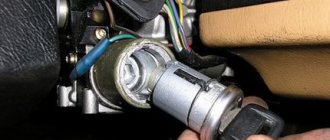
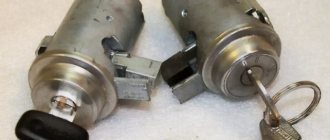
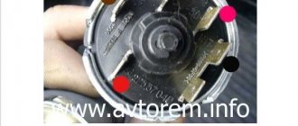
Dismantling the lock cylinder
Before starting this procedure, you need to “read” on the Internet recommendations for replacing the cylinder specifically for your car model, since there are thousands of possible options. It is possible that you will have to drill a hole in the lock structure, for example, as in GOLF 3.
Or AUDI.
In some cases, it is necessary to make “special tools”.
Repair of the lock cylinder
To carry out repairs, it is necessary to disassemble the larva. Its design can be complex, such as in BMW.
If you look closely, you can see that each element of the comb is signed with a two-digit code. We sell repair kits for lock cylinders of different car models. The main choice of repair option is faced by the car owner and the specific situation.
If you have three or four good keys for the car, it is better to purchase a repair kit and “reassemble” the cylinder. Anyone can do this, even without special knowledge. The comb elements are sequentially inserted, starting from the first, and the key is inserted into the cylinder until the metal parts protrude from the cylinder. The element number is recorded. The procedure then continues for the next positions of the larva. The selection is lengthy, but overall the process is creative and entertaining.
There is a simpler and faster repair option. To do this, you need to insert the key into the cylinder along with all the filling and cut off everything that protrudes beyond its limits with an emery wheel. Check for protrusions when installing other keys. Fast, but this option reduces the car’s security against theft.
If your car only comes with one or two keys, it may be cheaper to buy a new key. Then you will have to reinstall the immobilizer chip in the new keys that come with the cylinder. It is necessary to disassemble the new keys and check if they have the necessary cavities to accommodate the chip. If the original keys contain electronics and buttons, this option will not work at all. There may be an option to replace only the metal part of the key.
General information about the brand
Domestic cars of the 2106 brand were manufactured for the purpose of operating on roads equipped with improved surfaces, regardless of weather conditions. The cars are equipped with a four-door all-metal sedan body.
Cars are equipped with carburetor gasoline engines, four-speed or five-speed gearboxes. There is an independent spring front suspension; The rear suspension is dependent spring. The car's braking system is dual-circuit; there are disc brakes on the front wheels.
The rear ones are equipped with drums. Cars of the VAZ 2106 family were equipped with radial tubeless tires. The steering column has an anti-theft device that is built into the ignition switch.
The modification range of the VAZ 2106 family includes:
- VAZ 2106, 21065-00 - equipped with a model 2106 engine;
- 21061, 21065-01 – equipped with a model 2103 motor;
- 21063 – there was an engine from 21011.
- Car brand 21065 is the luxury version of this family. It has the following differences from the 2106 model: it is equipped with a five-speed gearbox and a final drive with a gear ratio of 3.9. Some cars were equipped with a Solex-type carburetor and a contactless ignition system. The car's electrical equipment is complemented by an electrically heated rear window, halogen headlights and a rear fog lamp. The body has been modified: the upholstery and seat headrests have been updated; The car is supplemented with bumpers of the 2105 model. Spare parts for the presented vehicles are available everywhere. In addition, the electric power steering is a kind of “novelty”, so to speak, the trends of the 21st century are making themselves felt. Thanks to this, car maintenance and repairs are not a big problem.
Schemes of individual six units
Generator connection diagram
1 — battery VAZ-2106; 2 — “six” generator set; 3 - regulatory device designed to control the operating voltage parameter; 4 - lock; 5 — plastic module with safety elements; 6 - control light indicator that determines the battery charge; 7 - relay that protects the power line of the battery charge indicator light.
Starter wiring diagram
1 — car starter device; 2 - battery; 3 - generator set; 4 - ignition switch.
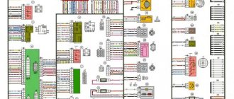
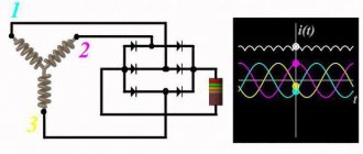
Electrical circuits of the contact ignition system
1 — spark plugs; 2 - distributor; 3 — ignition switch; 4 - coil; 5 - switch; 6 - generator; 7 - battery.
Carburetor valve control circuit
1 - limit switching device of the carburetor unit; 2 - the engine valve itself; 3 - module used to control the carburetor unit; 4 — ignition coil; 5 - switching device; 6 - ignition switch, is a lock.
Wiring diagram of direction indicators and signaling
1 — lighting devices for turning lights installed in the front optical devices; 2 — battery VAZ-2106; 3 - car generator unit; 4 — side turning lights located on the front fenders; 5 — main mounting module with safety elements; 6 - auxiliary control unit with safety devices; 7 — ignition switch; 8 - device for turning off and activating the light signal, mounted in the car interior on the center console; 9 - switching device for activating and disabling turning lights; 10 - interrupting device used for blinking turning lights and light signals; 11 — speedometer, equipped with a control light indicator for activation of turning lights; 12 — light devices for direction indicators in the rear optics.
Electrical circuit for turning on the sound
1 - sound devices used to reproduce impulses; 2 - relay for activation of sound impulses, protects the electrical circuit from overvoltage; 3 — switch of sound pulses; 4 — mounting module with safety elements; 5 — generator set VAZ 2106; 6 - battery.
Switching diagram for electric windows
1 - main safety module; 2 - relay used to protect the power line of additionally installed power windows; 3 — switching device for the electric window mounted on the left door; 4 - a similar device used to adjust the position of the glass in the front right door; 5 — electric motor of the left glass lift; 6 — auxiliary module with safety elements; 7 - ignition switch.
Engine cooling system diagram
1 — generator unit, installed under the hood; 2 - battery; 3 - ignition switch or lock; 4 — main module with safety elements; 5 - relay that protects the power line of the activation system of the electric motor of the power unit cooling fan; 6 — ventilation device activation controller; 7 - the fan itself; 8 - auxiliary safety module.
Ignition circuit for VAZ 2106
The VAZ 2106 ignition circuit includes an ignition distributor, a coil, spark plugs, a lock and low and high voltage wires. The VAZ 2106 connection diagram for this car system is shown in the photo.
- Until 1980, machines of this brand were equipped with the R-125B distributor. It was installed together with carburetors of type 2103. This distributor had a mechanical octane corrector, with which it was possible to slightly change the ignition timing, however, at the same time, there was no special vacuum regulator. After 1980, when engines were equipped with carburetors 2107-1107010-20 (“Ozone”), they began to use a 30.3706 distributor, which had a vacuum ignition timing regulator.
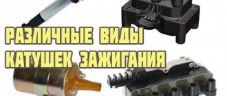
- The coil used was type B117-A. There was an open magnetic circuit. The device is oil-filled and sealed.
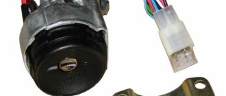
- Spark plugs of type A17DV or similar ones, but of foreign manufacture, were used.
- The cars were equipped with a VK347 lock, which had an anti-theft device. It works as follows: when the key is removed (from position III “Parking”), the locking rod extends from the switch body in a special way. It fits into the groove of the steering shaft and thus the shaft is blocked.
Starting the engine and setting the ignition
If during the process of replacing the elements you did not move the marks and connected the wiring correctly, then the “six” will start immediately. Let it warm up for a minute or two, manipulating the accelerator pedal, and then proceed to adjust the ignition. This is done in two ways:
- the most common method is “by ear”;
- using a special device - a strobe light.
Advice. If the car engine does not start and does not show signs of life when the starter rotates, then you should check that the high-voltage wires are connected correctly. Reason two: during installation, you turned the distributor cap 180°, causing the slider to transmit impulse to the 4th cylinder instead of the first and vice versa.
The ignition timing is adjusted by turning the distributor housing
Adjusting the ignition “by ear” is done as follows:
- With the engine running, loosen the distributor mounting nut.
- Slowly turn it clockwise and counterclockwise, achieving the most stable operation of the power unit. The rotation angle should not exceed 15°.
- Having grasped the position of clear engine operation, finally tighten the distributor nut.
With the help of a stroboscope, the ignition timing is set much more accurately. If you managed to get hold of this device or borrow it somewhere, then connect it to the battery terminals and the high-voltage wire of the first cylinder. Start the engine and carefully bring the flashing lamp to the marks on the block. A stroboscope will help you see the position of the mark stamped on the pulley while the engine is running. Now you can loosen the distributor nut and turn the housing to align this mark with the last, shortest mark.
Repairing a carburetor is not difficult if you know all the intricacies of the procedure:
This is what a strobe looks like for adjusting the advance angle
After adjustment, warm up the car to operating temperature and try driving it in different modes. If you hear a knocking noise from the piston pins when you press the gas pedal sharply, then you are dealing with detonation caused by too early ignition. Loosen the distributor fastening and turn it clockwise 1-2°, no more. The knocking should disappear.
Advice. After installing the BSZ, it often happens that the engine speed at idle increases due to better spark formation. The speed is reduced to 850-900 rpm using the fuel quantity screw. In Ozone carburetors, this is a large screw located on the right (in the direction of travel) at the bottom of the unit. In Solex carburetors, this is a plastic handle that protrudes from the rear and rests against the valve axis. It is not allowed to touch a “quality” screw without knowing the matter!
2sh.jpg
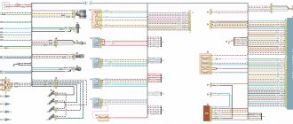
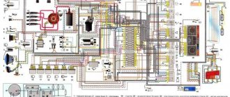
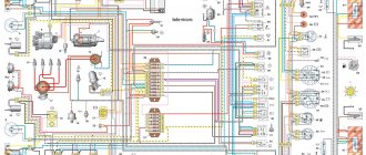
The VAZ 2106 electrical circuit diagram is a detailed “plan” on the basis of which the entire system of electrical connections of the vehicle operates. It consists of:
1 — front lights; 2 — side direction indicators; 3 - battery; 4 - relay from the battery charge warning lamp; 5 – relay with which the low beam headlights are turned on; 6 — relay for high beam headlights; 7 – car starter; 8 - generator; 9 – high beam lighting devices (headlights); 10 — low beam devices; 11 – sensor with which the fan motor is turned on; 12 — electric motor of the SOD fan (engine cooling system); 13 – horn (sound signal); 14 — ignition coil; 15 – ignition distributor; 16 — spark plugs; 17 – carburetor solenoid valve; 18 – sensor that shows the coolant temperature; 19 — engine compartment lamp; 20 – car reverse light switch; 21 – sensor indicating the oil pressure level; 22 — oil pressure sensor; 23 - sensor from the warning lamp, indicating the brake fluid level; 24 – electric motor, which is used by the windshield wiper; 25 — switch (equipped if a non-contact ignition system is used); 26 – electric motor from the windshield washer; 27 — fan motor relay; 28 – machine voltage regulator; 29 – special relay-breaker for the windshield wiper; 30 – special additional fuse block; 31 — main fuse block; 32 — relay-breaker for car alarms and corresponding direction indicators; 33 – relay with which the rear window heater is turned on; 34 — brake light switch; 35 – special plug socket for a personal transport lamp (not installed since 2000); 36 – special additional resistor of the automobile electric heater motor; 37 – electric motor, without which the heater cannot operate; 38 – mandatory switch for the heater electric motor; 39 – machine clock; 40 – lamp that illuminates the glove box; 41 — car cigarette lighter; 42 — alarm switch; 43 – special regulator for lighting transport devices; 44 - warning lamp, which symbolizes insufficient brake fluid level; 45 – light switch for headlights, sound signals and direction indicators; 46 — car ignition switch; 47 — rear window heater switch; 48 — car rear fog lamp switch; 49 — external lighting switch VAZ 2106; 50 — door lamp switches (A-pillars); 51 — electric window motor (some of the manufactured vehicles are equipped with it); 52 — door lamp switches (rear pillars); 53 — switch for the warning lamp of the car parking brake; 54 – lampshades that provide interior lighting; 55 - fuel level indicator in the car, which has a reserve warning lamp; 56 — coolant temperature indicator; 57 - oil pressure indicator, equipped with a warning lamp for insufficient pressure; 58 – car tachometer; 59 — control lamp (CL) of the parking brake; 60 – battery charge CL; 61 — CL carburetor air damper; 62 — side light CL; 63 — CL turn indicators; 64 — CL main beam headlights; 65 — auto speedometer; 66 — carburetor choke switch CL; 67 – “left-door” switch for the electric window motor; 68 – automotive power window relay; 69 – “true” switch for the electric window motor; 70 — rear transport lights; 71 – lights that illuminate license plates; 72 – sensor showing fuel level and reserve; 73 — rear window heater; 74 – lamp used to illuminate the trunk; 75 — rear traffic fog lamp.
Injection engine control unit diagram
Electrical connection diagram for the injection engine control system:
1. — Controller connector. 2. — Mass air flow sensor. 3. — Coolant temperature sensor. 4. — Crankshaft position sensor. 5. — Throttle position sensor. 6. — Oxygen concentration sensor. 7. — Speed sensor. 8. — Ignition module. 9. — Electromagnetic valve for purge of the adsorber. 10. — Electric fan relay. 11. — Electric fuel pump relay. 12. — Main relay. 13. — Fuse protecting the power circuit of the electric fuel pump relay. 14. — Fuse protecting the power circuits of the main relay. 15. — Fuse link. 16 - Fuse protecting the constant power supply circuit of the controller. 17. — Diode. 18. — Idle speed regulator. 19. — Injectors. X1. — Diagnostic block. X2. — Connection block to the vehicle electrical system.
5avz.jpeg
The VAZ 2106 fuse diagram is one of the simplest. It presents two lines with automotive fuses. This structure is attached with two nuts to the machine body. If you need to remove the fuse line, you will have to disconnect the battery. The disadvantages of such a fuse circuit (block) are its inconvenient covers.
The main disadvantage is that due to the unbending legs, contact sometimes disappears. And in some cases, as a result of poor contact, the fuse heats up and, as a result, the plastic ruler melts. This drawback can easily be corrected by replacing the block with fork-shaped fuses. It will take 10 minutes, but in the future, thanks to this “do-it-yourself VAZ 2106 tuning”, you will get rid of various hassles associated with electricity.
Connection diagram for the electric motor of the interior heater fan
| Position number on the diagram | Explanation of position |
| 1 | Generator |
| 2 | Battery VAZ-2106 |
| 3 | ignition switch |
| 4 | main fuse box |
| 5 | heater fan switch |
| 6 | additional resistor |
| 7 | electric motor of the interior heater fan ME-255 |
Ignition system VAZ 2106
The VAZ-2106 car is mainly equipped with a classic electric ignition system.
On the modified VAZ 21065 model, contactless systems were installed. In the classic form, B117A coils are used, in the non-contact system - 27 3705, the main difference of which lies in some details and winding data. The history of the production of the famous VAZ “six” VAZ 2106 dates back to 1976. From the very beginning of its production, a classic of the domestic automobile industry, equipped with an 80 hp engine. forces, has become the most popular and sought-after model among car enthusiasts.