An external magnetic tap made of transformer steel is installed inside the housing. The first step is to check the current flow channel to the central wire of the breaker-distributor, or, as it is popularly called, the distributor. Where to direct each subsequent spark is determined by the distributor, which is also the main ignition distributor. The spark is supplied to the cylinders in pairs using the idle spark method. Operating principles of the ignition coil
This is a traditional, common VAZ ignition coil, used for a long time and on many other cars. One end of the secondary winding is connected to the high-voltage terminal, and the second to the ignition coil housing, to ground.
The slightest electrical breakdown under such conditions is possible only in the presence of very high voltage. Otherwise, it will work for some more time and you will have to return to this topic again.
Design Fundamentally, the ignition coil is very simple. The rotor consists of an annular permanent magnet 26 and two pole pieces 25 and 27, located at both ends of the permanent magnet. An additional resistor can be mounted either on the coil itself or separately from it. A simple check of the ignition coil! Check the voltage!
Checking the coil's health
The short circuit is tested in the following order:
Checking spark plugs; visual inspection of wiring; voltage measurement; determination of the resistance value.
When examining the external parts of the coil, you must first of all pay attention to:
Wire connection points; external mechanical damage; presence of dirt and oil stains.
To make sure that there is voltage, turn on the ignition and measure the readings by connecting a voltmeter to ground and terminal “B”. If there is no breakdown on this side, then you will have 12 volts. If there is no voltage, you will have to deal with the lock.
Before starting work on the vehicle's on-board electrical system, it is mandatory to disconnect the negative terminal from the battery - this is a safety rule.
For the following tests, the short circuit must be completely dismantled. We'll tell you how to do this below.
The primary winding is checked for an open circuit with an ohmmeter (set to 200 Ohms). Here:
One probe is connected to terminal “B”; others touch exit “K”. normally the indicator will be 3.8-4.5 ohms.
The high voltage part is tested differently:
The device is set to 20 kOhm; one probe is placed on “K”; the second is on the high-voltage contact (located in the center); The normal value is from 7 to 8 kOhm.
The last stage is checking for insulation breakdown. Here:
The device remains at 20 kOhm; the black probe is applied to the body; red - alternately to all outputs; in the absence of breakdown, the ohmmeter readings will not change.
Any deviation from the above standard values means that the closing coil is faulty.
The most common problems with coils are:
Overheating of windings; short circuit in one of them.
Similar troubles occur when the engine is operated incorrectly with unadjusted (too wide) spark plug gaps or when there is poor contact in the terminals or partial breakage of the wiring.
By the way, installing high-quality spark plugs and their correct adjustment significantly increases the service life of the reel.
see also
Comments 20
Thanks everyone for the advice! I installed the VAZ coil, connected the wires, and started the car!
There is no spark not with this not with the VAZ coil :(
Green, light green, yellow, brown + from distributor
The coil needs another one with two contacts B-battery K-cams, tachometer
Is the wire from the distributor also on “K”?
Yes, in the place with the tachometer, I have a green wire, and a yellow one is plus
The entire bunch is connected to terminal K green. and brown?
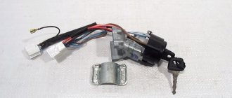
the coil is from Ufa, on the VAZ there is nowhere to connect the third terminal - there is no terminal for it on the starter... I would change the coil to the VAZ one... if you connect this one, you find the wire on which + appears when you turn on the ignition and hang it on B, you hang the rest if you look in the photo, then to the lower contact, these are wires from the distributor and from the tachometer...
I connected everything like this, but there is no spark! Even when you turn on the low beam, the side lights go out, and the turn signals on the rear headlights come on and the low beam doesn’t light up, the rear right side light doesn’t light up yet
Is the coil definitely alive? try to directly close the variator, they sometimes burn out, you can’t drive with it closed, the coil will burn out, but you can’t close it for long to check... well, and again check the contacts in the distributor, the capacitor... as for the light and music - look for where the ground on the headlights is lost...
The distributor is new! I plugged a light bulb into the high-voltage wire from the coil to the distributor, placing it on - (radiator) did not light up when starting the starter
Is the coil definitely alive? try to directly close the variator, they sometimes burn out, you can’t drive with it closed, the coil will burn out, but you can’t close it for long to check... well, and again check the contacts in the distributor, the capacitor... as for the light and music - look for where the ground on the headlights is lost...
I also accidentally connected the wire from the distributor to the terminal of the coil with the + terminal from the ignition; the distributor was short-circuited; the contacts in the distributor and the ends of the wires of the distributor and + from the ignition melted. Could this cause the coil to burn out?
Russian spare parts are so Russian that new does not mean working, everything needs to be checked. I don’t understand, why is there a light bulb there? you hold the high voltage wire with a gap from any ground and turn the starter, see if there is a spark... if the contacts in the distributor are already burnt, all the more you need to get into it, clean the contacts, set the gap... but I would still change the coil to a VAZ B117...
I replaced the shorted distributor with a new one, and I will change the coil tomorrow with the high-voltage wires! Does the coil take minus from the body?
the plus goes to the coil from the lock, and the minus comes from the distributor, the contact group is at ground...
B - 'battery' - the wire on which 12V appears when the ignition is turned on. 'Unnamed' - to the distributor, there is also a wire from the tachometer. On 'Vk' there is a wire from the starter, to enhance the spark at the moment of starting
The colors of the wires do not match and in the diagram with the VAZ internal combustion engine there is a coil with 2 terminals
Source: www.drive2.ru
How to connect a coil
The ignition coil, in principle, cannot be disassembled, for this reason it cannot be repaired. Thus, if it is possible to find out that it is the short circuit that has failed, it is simply replaced with a working unit.
To complete this task, prepare:
Pliers; or 8 and 10 mm spanners.
The procedure is as follows:
First of all, we disconnect the battery - the coil is a fairly powerful transformer, so the likelihood of getting an electric shock is quite high; then remove the high-voltage wire from the corresponding connector; unscrew the nuts from both terminals of the winding terminals - “K” (or OE) and “B”; we screw together the fasteners holding the unit on the machine body; dismantle the short circuit and put a working one in its place; We carry out the assembly in the reverse order.
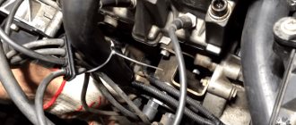
Sometimes car enthusiasts have to deal with the following situation: the “six” does not start from the starter. As a rule, the problem lies in the ignition system, or more precisely, in the failure of some element of this system. The first step is to check the current flow channel to the central wire of the breaker-distributor, or, as it is popularly called, the distributor.
Malfunctions
Typical breakdowns for the BSZ system are:
- Hall element failure. The engine suddenly stalls or does not start.
- Burning of the contact of the high-voltage wire. A common malfunction for all ignition systems. The engine stalls or starts poorly.
- Damage to the contact groups of the device. Here, a common cause is banal oxidation of the terminals.
- Controller failure. This can happen due to overheating, water ingress or mechanical impact.
No spark on electronic ignition
The reasons for the loss of spark on a contactless module are usually not very different from similar problems with classical elements.
- Damage to the spark plug or high-voltage wire. These parts are most susceptible to vibration and other negative factors.
- If the ignition periodically fails, check the contact groups and wiring for oxides and damage.
- The control equipment is damaged. There may be a controller or a Hall sensor here.
Lada 2106 won't start
If the car does not start, an experienced motorist can immediately identify the circuit that is failing. If the problem is the ignition, you will need to check the circuit for faults. Usually they start with candles and end with a coil.
If a damaged part is found, it is replaced with a known good one.
Checking the ignition coil
For this purpose, it is necessary to remove the central wire from the breaker-distributor, bring it to the motor housing and turn it with the starter, and a running spark should appear. After this, we check the energy supply to a separate spark plug, for which we unscrew the working spark plug, bring its contact to ground and attempt to start the engine. In this case, the spark should come from the wire to ground. If it is absent, the reason will be a malfunction of such a system element as the VAZ 2106 ignition coil, which plays an important role in the operation of the vehicle.
During the inspection, it is necessary to observe safety precautions and work in protective dielectric rubber gloves. The “six” uses both an ignition system using contacts and a system without using distributor contacts with equal success; accordingly, a different VAZ 2106 coil is used, depending on the type of ignition system.
These types of ignition are checked using almost the same parameters. In this case, we test the system with a multimeter. It must be remembered that in the connection circuit of the VAZ 2106 ignition coil, the voltage in sections of the circuit reaches from 24 thousand to 40 thousand volts. With a small current in the system, this is not life-threatening, but an electric shock can be very sensitive.
Important: To be on the safe side, it is advisable to keep an additional ignition coil and distributor capacitor in the car. These elements of the system quite often cause the system to fail, and such products cannot be repaired. If these components are defective, it is not possible to start the engine, but replacing them is not difficult. As a last resort, in the absence of standard products, you can temporarily install analogues from other VAZ models.
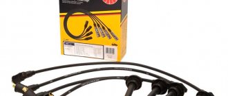
Armored wires
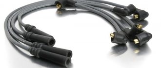
High voltage wires serve to transmit pulse voltage from the ignition coil to the fixed contacts of the distributor cover, and from there to the central electrodes of the spark plugs. The VAZ 2107 has five such wires. Structurally, each of them consists of a conductive core, several layers of insulation (PVC or silicone) and tips.
The set consists of five wires: four transmit voltage to the spark plugs, and the fifth serves to supply it from the ignition coil to the distributor
Wire faults
Armored wires can have only three faults:
- breakdown of the insulating layer;
- breakage of the current-carrying conductor;
- core wear.
Failure of one or more high-voltage wires at the same time is accompanied by the following symptoms:
- “triple” of the motor;
- its difficult to start;
- drop in power unit power;
- increase in the amount of fuel consumed.
How to check high voltage wires
Checking armored wires consists of determining the integrity of their insulation and establishing the resistance of the current-carrying conductors. To assess the condition of the insulating layer, it is enough to remove the wires, clean them of dirt and inspect them by twisting and bending them in your hands. If during such a check it is discovered that at least one of them has cracks, severe abrasions, or traces of electrical breakdown, the entire set should be replaced.
Long-term operation of high-voltage wires leads to wear of the current-carrying core, as a result of which its resistance changes up or down. Naturally, this affects the magnitude of the transmitted voltage and spark energy.
The process for measuring wire resistance is as follows:
- Turn on the ohmmeter and set it to the range 0–20 kOhm.
- We connect the probes of the device to the ends of the current-carrying wire.
- We look at the ohmmeter readings. Serviceable wires, depending on the manufacturer and service life, can have a resistance in the range of 3.5–10 kOhm. If the indicators are different, we change the wires as a set.
The core resistance should be in the range of 3.5–10 kOhm
Video: checking armored wires
VAZ 2106 ignition coil diagram
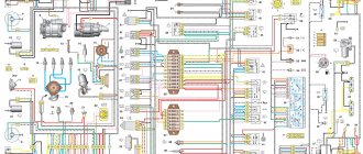
The standard ignition coil of the VAZ 2106 is a sealed technical vessel filled with special oil, with an open-type magnetic circuit. The schematic diagram of the ignition system is located below:
where: 1 – generator; 2 – ignition switch; 3 – distributor; 4 – distributor cam; 5 – candles; 6 – ignition coil; 7 – battery.
The correct connection of the ignition coil of a VAZ 2106 can be found here:
Checking the ignition coil:
- At the initial stage, you need to find out how the current “comes” to the ignition coil, for which: turn on the ignition and use a multimeter to measure the voltage with the ignition on at contact B+ of the product and ground, which should be 12 V. If there is no voltage, then the reason is ignition switch.
- To start the engine in emergency mode, the positive wire from the battery must be connected to the B+ mount of the bobbin. If current “comes” to the ignition coil in the absence of a spark, then it is necessary to test the resistance of both circuits (windings) of the product.
- To measure the resistance values of the primary winding, the “crocodile clips” of the multimeter are connected to the 2 contacts of the coil on the sides of the product, and the meter should produce measurement values of 3-4 Ohms.
- To measure the resistance values of the secondary winding, the “crocodile clips” of the multimeter are connected as follows: the first one to the main output contact of the coil, and the second to the side contact, and the meter should produce measurement values of 7-9 kOhm.
With a working VAZ 2106 ignition coil, the price of which is acceptable for many car enthusiasts, the reason mainly lies in the distributor-breaker. It is forbidden to allow a long period of checking the spark distance between the wiring and ground; this may cause a defect in the bobbin. Due to the increased distance, the ignition coil “breaks through” from the inside.
Malfunctions of the ignition coil of VAZ 2106
There are individual malfunctions of the ignition coil that lead to replacement of the product. These include external mechanical deformations of the product and breaks in the coil windings. A malfunction of the VAZ 2106 ignition coil is classified as a condition when the ignition coil heats up to a high temperature.
Slight heating of the product is the normal state of this part when the ignition is turned on and the distributor contacts are closed with a contact ignition system. If you doubt the functionality of this part of the ignition system, we recommend checking the coil for the resistance of both windings of the product.
For a gasoline internal combustion engine, the ignition system is one of the determining ones, although it is difficult to single out any main component in the car. You can’t go without a motor, but it’s also impossible without a wheel.
The ignition coil creates high voltage, without which it is impossible to form a spark and ignite the fuel-air mixture in the cylinders of a gasoline engine.
Candles
The spark plug's job is to create a powerful electric spark to ignite the air-fuel mixture. The basis of the candle design is:
- a central electrode through which high voltage current flows;
- ceramic insulator;
- threaded part (skirt);
- side electrode
What spark plugs are used in the BSZ VAZ 2107
In electronic BSZ it is recommended to use spark plugs of the following manufacturers and types:
- A17DV and their modifications (Russia, Engels, ZAZS);
- BP-6 E (Japan, NGK);
- W20-EP (Japan, DENSO);
- L15Y (Czech Republic, BRISK);
- W-7D (BERU Germany, BERU).
The interelectrode gap for spark plugs for BSZ should be in the range of 0.7–0.8 mm
Table: main characteristics of BSZ spark plugs
| Characteristics | Indicators |
| Height of the threaded part, mm | 19 |
| Thread type | M14/1.25 |
| Heat number | 17 |
| Gap size, mm | 0,7–0,8 |
Briefly about ignition
To understand why there is a reel in a car (this is a popular name), and what part it takes in ensuring movement, you need to at least generally understand the structure of ignition systems.
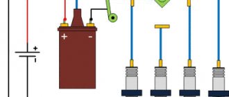
A simplified diagram of how the reel works is shown below.
The positive terminal of the coil is connected to the positive terminal of the battery, and the other terminal is connected to the voltage distributor. This connection scheme is classic and is widely used on VAZ family cars. To complete the picture, it is necessary to make a number of clarifications:
- The voltage distributor is a kind of dispatcher that supplies voltage to the cylinder in which the compression phase has occurred and the gasoline vapors should ignite.
- The operation of the ignition coil is controlled by a voltage switch; its design can be mechanical or electronic (contactless).
Mechanical devices were used in old cars: the VAZ 2106 and the like, but now they are almost completely replaced by electronic ones.
Reel design and operation
The modern bobbin is a simplified version of the Ruhmkorff induction coil. It was named after the German-born inventor Heinrich Ruhmkorff, who was the first to patent a device in 1851 that converts low-voltage direct voltage into high-alternating voltage.
To understand the principle of operation, you need to know the structure of the ignition coil and the basics of radio electronics.
This is a traditional, common VAZ ignition coil, used for a long time and on many other cars. In fact, this is a pulse high-voltage transformer. On a core designed to enhance the magnetic field, a secondary winding is wound with a thin wire; it can contain up to thirty thousand turns of wire.
On top of the secondary winding is a primary winding made of thicker wire and with fewer turns (100-300).
The windings at one end are connected to each other, the second end of the primary is connected to the battery, the secondary winding with its free end is connected to the voltage distributor. The common point of the coil winding is connected to the voltage switch. This entire structure is covered by a protective housing.
A direct current flows through the “primary” in the initial state. When a spark needs to be formed, the circuit is broken by a switch or distributor. This leads to the formation of high voltage in the secondary winding. Voltage is supplied to the spark plug of the desired cylinder, where a spark is formed, causing combustion of the fuel mixture. High-voltage wires were used to connect the spark plugs to the distributor.
The single terminal design is not the only one possible; there are other options.
- Double spark. The dual system is used for cylinders that operate in the same phase. Let's assume that compression occurs in the first cylinder and a spark is needed for ignition, and in the fourth cylinder there is a purge phase and an idle spark is formed there.
- Three-spark. The principle of operation is the same as that of a two-terminal one, only similar ones are used on 6-cylinder engines.
- Individual. Each spark plug is equipped with its own ignition coil. In this case, the windings are swapped - the primary is located under the secondary.
Share your story
The tightness of the carbolite lid in the casing is ensured by a gasket. As a result, high voltage is formed in the secondary, which goes through high-voltage wires to the spark plug. According to the design of the magnetic circuit, ignition coils are divided into two types: - With an open magnetic circuit. Types of high-voltage elements Above is a description of a simple design of a voltage-increasing transformer that provides discharges to all engine cylinders.
When the engine crankshaft rotates, the sensor rotor rotates.
Replacing the ignition coil on a VAZ is quite simple.
Capacitors C1 and C2 and the inductor reduce voltage ripple in the switch's power circuit, and the VD6 diode KDB protects against reverse polarity. The dual system is used for cylinders that operate in the same phase. Direct current flows through the primary coil.
TB above emitter potential. When connecting the coil to the car’s ignition system, in principle, you should not have any difficulties if, during preliminary dismantling, you marked or remembered which wires are connected where. Ignition system contact and without 1 part
How to check the ignition coil
The main parameter by which the performance of the reel is determined is the resistance of the windings. There are average indicators that indicate its serviceability. Although deviations from the norm are not always an indicator of a malfunction.
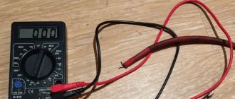
Using a multimeter
Using a multimeter, you can check the ignition coil according to 3 parameters:
- primary winding resistance;
- secondary winding resistance;
- presence of a short circuit (insulation breakdown).
Please note that only an individual ignition coil can be checked in this way. Dual ones are designed differently, and you need to know the output circuit of the “primary” and “secondary”.
We check the primary winding by attaching probes to contacts B and K.
When measuring the “secondary” we connect one probe to contact B, and the second to the high-voltage terminal.
The insulation is measured through terminal B and the coil body. The device readings should be at least 50 MΩ.
It’s not always common for a car enthusiast to have a multimeter at hand and experience in using it; on a long journey, checking the ignition coil using this method is also not available.
other methods
Another method, especially relevant for old cars, including VAZs, is to check the spark. To do this, the central high-voltage wire is placed at a distance of 5-7 mm from the motor housing. If a blue or bright purple spark flashes when you try to start the car, the reel is working normally. If the color of the spark is lighter, yellow, or absent altogether, this may confirm that it is broken or the wire is faulty.
There is an easy way to test a system with individual coils. If the engine stalls, you just need to disconnect the power to the coils one by one while the engine is running. We disconnected the connector and the operating sound changed (the machine stalled) - the coil is fine. The sound remains the same - there is no spark to the spark plug in this cylinder.
True, the problem may also be in the spark plug itself, so for the purity of the experiment, you should swap the spark plug from this cylinder with any other.
Instructions for installing a contactless system
The procedure for replacing a mechanical ignition with an electronic one is divided into the following stages:
- selection and purchase of BSZ;
- preparation of tools;
- removing the old system and installing a new one;
- ignition setting.
If you have not previously had to deal with sparking problems in classic Zhiguli models on your own, then you will have to allocate about 3-4 hours for all the work.
Recommendations for selection
The BSZ factory kit for the VAZ 2107, available for sale, includes the following parts:
- switch with catalog number 36.3734 (also available 3620.3734);
- main ignition distributor, marking - 38.37061;
- high-voltage coil, catalog number - 27.3705;
- wiring harnesses with connectors.
BSZ parts from SOATE company
Note. The marking of the distributor is indicated for cars with engines of 1.5 and 1.6 liters. In modifications of the “Seven” with a 1.3 liter engine, the cylinder block is smaller in height and the ignition distributor shaft is shorter. Its catalog number is 38.3706–01.
There is a similar contactless kit on sale, designed for the Russian SUV VAZ 2121 Niva. In it, the distributor is marked as follows: 3810.3706 or 38.3706–10. You should not buy it for the “classics”, since the element differs in technical parameters, although it looks the same in appearance.
Among the manufacturers producing ready-made electronic ignition kits for older VAZ models, the one that has proven itself to be the best is VAZ, whose production is located in Stary Oskol, Russian Federation. Feedback from owners of “classics” about the company’s products is purely positive.
It is recommended to change the spark plugs and wires along with the ignition.
Advice. When planning to set the BSZ to "seven", at the same time replace the spark plugs (brand - A17DVR) and the high-voltage wires to them. They are not included in the delivery package, but they are very useful for stable and economical operation of the engine with the new spark generation system.
What tools will you need?
To install the electronic unit and other elements of the UPS, you will need simple tools available in the garage of any skilled motorist:
- flathead and Phillips head screwdrivers;
- open-end wrenches sizes 8, 10 and 13 mm;
- ordinary pliers;
- a spark plug wrench equipped with a cardan for convenience;
- hand or electric drill with a drill with a diameter of 3-3.5 mm.
From this set you will need keys, screwdrivers and pliers
Note. Using keys, you unscrew the terminals, distributor fastenings and coils. A drill will be needed to make 2 holes for mounting the switch. In some cars you can find ready-made holes designed for mounting electronics; they are located on the left side member (in the direction of travel of the car).
With a 30 mm wrench you can easily turn the crankshaft
It’s good if you manage to find and borrow a special wrench designed to turn the crankshaft of a VAZ 2107 by grabbing the ratchet nut. Another option is to rotate the crankshaft with a regular 30 mm open-end wrench or by turning the suspended rear wheel with 4th gear engaged.
Work on installing and configuring contactless ignition can be carried out in any convenient place, as long as weather conditions permit. Since you don’t need an inspection hole, a flat and well-lit area will do.
Installation of BSZ on a car
Before installing the electronic ignition, you need to remove the old system from the car, proceeding in this order:
- Lift the hood cover of the "Seven", disconnect the battery from the on-board network and remove the high voltage wires from the spark plugs.
- Remove the spark plugs and turn the crankshaft to bring the piston of cylinder 1 to top dead center (TDC). A long screwdriver inserted into the spark plug well will help you with this. Make sure that the notch on the crankshaft pulley is opposite the first mark on the cylinder block (it is the longest of the three).
- Unlock the metal latches of the ignition distributor cover and remove it along with the wires. To be sure, place a mark on the engine valve cover opposite the moving contact of the slider.
- Disconnect all wires from the distributor and the thin tube that connects it to the fitting on the carburetor. Loosen the nut holding the distributor skirt to the cylinder block and unscrew it. Remove the old distributor, making sure that the gasket is not lost (it is located between it and the block).
- Disconnect the wires from the contacts of the high-voltage coil and remember where they were connected. Unscrew the coil bracket and remove it from the body.
Disconnecting the negative terminal of the battery
Start installing the BSZ by installing an electronic unit equipped with an aluminum mounting plate with holes (it serves as a cooling element for the device). If there are ready-made holes on the left side member, screw the commutator to them with two self-tapping screws. Otherwise, find a free space near the coil, drill holes and secure the control unit.
Spark plug placement
Advice. Do not place the switch under the windshield washer fluid reservoir. If it leaks, it will flood the delicate electronics and the ignition will stop functioning.
To replace the coil, you need to disconnect the wires and remember their pinout
Install the elements of the contactless system in the following sequence:
- Take a new distributor, remove the cover from it and put on the gasket. Install it into the socket on the cylinder block so that the movable contact is opposite the chalk mark drawn on the engine valve cover. Lightly press the distributor skirt with the mounting nut to prevent it from accidentally turning.
- Screw the high voltage coil into the old place (the fastenings are the same). Connect the wires from the ignition switch relay, tachometer and switch to its terminals. The wire coming from contact “1” of the electronic unit is connected to the terminal marked “K” of the coil, and the wire from contact “4” is connected to terminal “B”.
- Having established a gap of 0.8-0.9 mm between the electrodes of the spark plugs, screw them into the holes of the cylinders. Place the cap on the distributor and connect all the high voltage wires, including the central one leading to the coil. Connect the vacuum tube, after which you can start starting the engine and adjusting the timely spark formation.
The notch is placed opposite the long score
Advice. When installing a high-voltage coil, the terminals are swapped, which causes some inconvenience. The issue is solved by loosening the nut of the mounting clamp and turning the coil body 180°, after which it can be put in place.
Stages of ignition installation in photographs
Position of the slider when the marks are aligned
Before setting the marks, you need to remove the distributor cap
Unscrewing the wires of the old distributor
Removing the central high-voltage wire from the coil
When all the wires are removed and the fastening nut is unscrewed, the distributor is removed from the block
After installing the new coil, the wires are connected to the same terminals
High-voltage wires must be connected using the numbers on the cover as a guide.
The switch is attached to the spar with 2 self-tapping screws
Video material on replacing the ignition with an electronic one
Connecting the ignition coil
If during dismantling you did not remember and did not mark which wire went to which terminal, the ignition coil connection diagram is as follows. The terminal with the + sign or the letter B (battery) is supplied with power from the battery, and the switch is connected to the letter K. The colors of the wires in cars may vary, so it is easiest to track which goes where.
The correct connection is important, and if the polarity is incorrect, the bobbin itself, the distributor, or the switch can be damaged.
Conclusion
One of the important components in a car is the bobbin, which creates high voltage to produce a spark. If dips appear in the engine’s operation, it begins to stall and simply run unstably – this could be the cause. Therefore, it is important to know how to check the ignition coil correctly, and if necessary, using the old-fashioned method, in the field.
If they have enough free time, domestic motorists often prefer to repair their “iron horses” themselves. In this regard, the vehicle ignition system is no exception. Experienced motorists know how to connect the ignition coil themselves, without resorting to the help of specialists from service shops.
However, such work is not characterized by a very high level of complexity. However, as practice shows, when carrying out repair work on a vehicle’s ignition system related to the repair of an inductor coil, even experienced car owners often forget about the wires with which insulation color should be connected to which terminals. In the future, this may cause certain difficulties during installation.
Step-by-step instructions on how to connect the ignition coil with your own hands:
1. First of all, it is necessary to remove the failed inductor. Next, a new ignition coil is installed in the vacant space. There is nothing complicated in this process, but many motorists, when installing a new element in the engine compartment, can be confused by the following: what color wire should be connected to which terminal.
2. For those car owners who have not yet been able to remember exactly what color wires to connect to which terminals, just in case, let us remind you: a wire with brown insulation is always connected to the “+” terminal of the ignition system coil - it must come from the ignition switch.
3. Accordingly, it is necessary to connect a wire with black insulation to terminal “K” - it connects the inductor and the terminal of the breaker-distributor of the car’s ignition system.
4. Last step: carefully tighten the nuts on the terminals of the coil and the “distributor”. The ignition coil has been connected, your vehicle is again ready for further use.
Connecting a magnetic starter and its small-sized variants is not difficult for experienced electricians, but for beginners it may be a task that requires some thought.
A magnetic starter is a switching device for remote control of high power loads. In practice, often, the main application of contactors and magnetic starters is the starting and stopping of asynchronous electric motors, their control and reversal of engine speed.
But such devices also find their use in working with other loads, such as compressors, pumps, heating and lighting devices.
For special safety requirements (high humidity in the room), it is possible to use a starter with a 24 (12) volt coil. And the supply voltage of electrical equipment can be high, for example 380 volts and high current.
In addition to the immediate task of switching and controlling high-current loads, another important feature is the ability to automatically “turn off” the equipment when there is a “loss” of electricity. A good example. While some machine, such as a sawing machine, was operating, the voltage in the network was lost. The engine stopped. The worker climbed to the working part of the machine, and then the tension appeared again. If the machine were controlled simply by a switch, the engine would immediately turn on, resulting in injury. When controlling the machine's electric motor using a magnetic starter, the machine will not turn on until the "Start" button is pressed.
Magnetic starter connection diagrams
Standard scheme. It is used in cases where it is necessary to carry out normal starting of an electric motor. The "Start" button was pressed - the engine turned on, the "Stop" button was pressed - the engine turned off. Instead of a motor, there can be any load connected to the contacts, for example a powerful heater.
In this circuit, the power section is powered by a three-phase alternating voltage of 380V with phases “A” “B” “C”. In cases of single-phase voltage, only two terminals are used.
The power part includes: a three-pole circuit breaker QF1, three pairs of power contacts of a magnetic starter 1L1-2T1, 3L2-4T2, 5L3-6T3 and a three-phase asynchronous electric motor M.
The control circuit receives power from phase “A”. The control circuit diagram includes the SB1 “Stop” button, the SB2 “Start” button, the magnetic starter coil KM1 and its auxiliary contact 13NO-14NO, connected in parallel to the “Start” button.
When the QF1 machine is turned on, phases “A”, “B”, “C” go to the upper contacts of the magnetic starter 1L1, 3L2, 5L3 and are on duty there. Phase “A”, which supplies the control circuits, comes through the “Stop” button to the “3” contact of the “Start” button, the auxiliary contact of the starter 13NO and also remains on duty on these two contacts.
note
. Depending on the voltage rating of the coil itself and the supply voltage used, there will be a different coil connection diagram. For example, if the coil of a magnetic starter is 220 volts, one of its terminals is connected to the neutral, and the other, through buttons, to one of the phases.
If the coil rating is 380 volts, one output is to one of the phases, and the second, through a chain of buttons, to the other phase. There are also 12, 24, 36, 42, 110 volt coils, so before you apply voltage to the coil, you must know exactly its rated operating voltage.
When you press the “Start” button, phase “A” hits the coil of the KM1 starter, the starter is triggered and all its contacts are closed. Voltage appears at the lower power contacts 2T1, 4T2, 6T3 and from them goes to the electric motor. The engine starts to rotate.
You can release the “Start” button and the engine will not turn off, since self-retaining is implemented using the auxiliary contact of the starter 13NO-14NO, connected in parallel to the “Start” button.
It turns out that after releasing the “Start” button, the phase continues to flow to the coil of the magnetic starter, but through its 13NO-14NO pair.
If there is no self-retaining, it will be necessary to keep the “Start” button pressed all the time so that the electric motor or other load runs.
To turn off the electric motor or other load, just press the “Stop” button: the circuit will break and the control voltage will stop flowing to the starter coil, the return spring will return the core with the power contacts to its original position, the power contacts will open and disconnect the electric motor from the mains voltage.
What does the installation (practical) diagram for connecting a magnetic starter look like?
In order not to pull an extra wire to the “Start” button, you can place a jumper between the coil output and one of the nearest auxiliary contacts, in this case these are “A2” and “14NO”. And from the opposite auxiliary contact the wire runs directly to the “3” contact of the “Start” button.
How to connect a magnetic starter in a single-phase network
Electric motor connection diagram with thermal relay and circuit breaker
How to choose a circuit breaker (circuit breaker) to protect the circuit?
First of all, we choose how many “poles”; in a three-phase power supply circuit, a three-pole circuit breaker will naturally be needed, and in a 220 volt network, as a rule, a two-pole circuit breaker will be sufficient, although a single-pole circuit breaker will be sufficient.
The next important parameter will be the operating current.
For example, if the electric motor is 1.5 kW. then its maximum operating current is 3A (real operating current may be less, it must be measured). This means that the three-pole circuit breaker must be set to 3 or 4A.
But we know that the starting current of the engine is much higher than the operating current, which means that a regular (household) automatic machine with a current of 3A will operate immediately when starting such an engine.
The characteristic of the thermal release must be selected D so that the machine does not trip when starting.
Or, if such a machine is not easy to find, you can select the current of the machine so that it is 10-20% greater than the operating current of the electric motor.
You can also go into a practical experiment and use a clamp meter to measure the starting and operating current of a particular motor.
For example, for a 4kW motor, you can install a 10A automatic.
To protect against motor overload, when the current increases above the set value (for example, phase loss), the contacts of the thermal relay RT1 open and the power circuit of the electromagnetic starter coil is broken.
In this case, the thermal relay acts as a “Stop” button, and is in the same circuit, in series. Where to put it is not particularly important, it can be in the section of the L1 - 1 circuit, if it is convenient for installation.
With the use of a thermal release, there is no need to so carefully select the current of the input circuit breaker, since the thermal protection of the motor should be quite adequate.
Instructions for setting the ignition
If you strictly followed the instructions, connected all the wires according to the diagram and did not misalign the marks, then the motor will start without problems. To adjust the ignition, you need to ensure stable engine operation, so first warm it up for a few minutes, without letting it stall by pressing the gas pedal.
Advice. If the engine does not start successfully, and when you turn on the starter there is not even a popping sound, then you probably made a mistake with the wiring. Check everything again according to the diagram included with the factory set of electronic ignition parts.
Adjustments can be made on a warm engine using two methods:
- without the use of special devices - “by ear”;
- fine adjustment using a strobe light.
A strobe is a device with a light bulb that flashes simultaneously with the transmission of a pulse by the Hall sensor. When the switched on strobe is brought to the crankshaft flywheel with the engine running, the position of the notch becomes visible. Hence the possibility of precise adjustment.
This is what a strobe looks like for fine-tuning the ignition
To set up, connect the strobe power supply to the battery, and the thick wire to the high-voltage wire of the spark plug of the 1st cylinder. Loosen the distributor fastening nut and bring the flashing lamp to the pulley. Slowly turn the distributor body until the notch on the pulley aligns with the short notch, then tighten the nut.
Tuning in the traditional way “by ear” is done like this:
- Start the engine and loosen the nut holding the ignition distributor.
- Rotate the distributor smoothly and slowly within 15°. Find the position at which the motor operates most stably.
- Tighten the fastening nut.
When adjusting, turn the distributor by the membrane body
Advice. When you turn the ignition distributor by hand, try not to touch the high voltage wires so that you do not get an electric shock. The best option is to grab the body of the membrane mechanism, where the tube from the carburetor is attached.
It is quite natural that after installing a contactless ignition system, the engine idle speed will increase to 1100-1200 rpm due to the increased spark power. Set the rate to 850-900 rpm by tightening the idle screw on the carburetor and using the tachometer as a guide. On VAZ 2105-2107 carburetors of the “Ozone” type, this screw is located in the lower section of the unit on the right side and is large in size. The VAZ 2108 carburetors of the Solex type (these were also installed on the “seven”) have a long plastic handle protruding from the right (in the direction of travel). The second screw, which regulates the composition of the air-fuel mixture, cannot be turned.
The arrow shows the idle speed adjustment screw.
Advice. If, when you sharply press the accelerator, a loud knock is heard from the engine, then you have set the ignition timing too high and the mixture flares up earlier than necessary. Loosen the distributor nut and turn the housing a couple of degrees clockwise.