Checking the camshaft sensor (abbr. DPRV) allows you to verify its functionality and make sure that in engines with phased (sequential) injection, fuel is supplied in exactly the required sequence. Another name for this device is a phase sensor (it is often used by owners of domestic VAZs). The test can be performed using a multimeter in voltmeter mode and/or an oscilloscope. Even a novice car enthusiast can check the camshaft position sensor.
What is a camshaft sensor
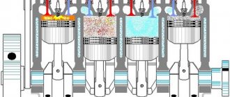
A camshaft sensor is a device that records the angular position of a specified shaft at a specific point in time. The information obtained with its help is transmitted to the electronic engine control unit (ECU), and on its basis this control element issues commands for fuel injection and ignition of the air-fuel mixture in each cylinder at a specific point in time.
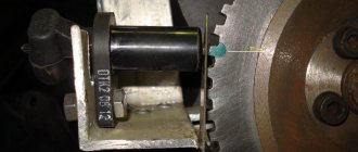
The operation of the camshaft position sensor is based on the Hall effect. So, directly on the camshaft there is a metal tooth, which, when the shaft rotates, changes the magnetic field in a nearby sensor. This tooth is called rapper.
The sensor detects a change in the magnetic field, which is converted into a low voltage electrical signal. This signal is sent to the electronic control unit.
In fact, the camshaft position sensor only registers one position, corresponding to the position of the piston of the first cylinder at top dead center. Next, phased fuel injection is performed in the firing sequence of the cylinders. Typically this is a 1-3-4-2 system.
Camshaft position sensors have been installed on engines with split (phased) fuel injection since approximately 2005.
If the camshaft sensor fails (the electronic control unit receives incorrect information from it or does not receive it at all), then it is programmed to switch to emergency mode. It involves the use of pairwise-parallel (group) fuel supply to the engine. This leads to two negative consequences:
- A slight loss of engine power, especially when driving in critical modes (acceleration, driving under load).
- Increase in fuel consumption by approximately 10...20% (depending on engine power, its design features, as well as operating conditions).
As for diesel engines, camshaft position sensors are designed similarly, but there is one difference. It lies in the fact that the sensor records the position of not only the first cylinder, but all of them. This is done due to the fact that the drive disk has a separate tooth for each cylinder.
Thus, if a sensor fails, it makes sense to diagnose it as quickly as possible and, if necessary, replace it.
Signs of DPRV failure
There are several typical signs that indicate that the camshaft position sensor has failed. It is immediately necessary to clarify that the symptoms listed below may indicate completely different malfunctions. Therefore, it makes sense to perform additional diagnostics. So, signs of a DPRV breakdown:
- Problems with starting the engine, under any conditions - “cold”, “hot” and in other modes. This usually results in having to crank the starter longer.
- Unstable engine operation, “floating” operating and idle engine speeds.
- “Dips” in the movement of the car; when you press the accelerator pedal, it does not respond immediately, the dynamic characteristics of the car are lost (it accelerates poorly, does not pull, especially when loaded and when moving uphill).
- When the accelerator pedal is released, the engine stalls.
- Increased fuel consumption (by 10...20%).
- The Check Engine warning light on the instrument panel activates. It is necessary to perform additional diagnostics using an electronic scanner (for example, an ELM 327 device or its equivalent). In this case, typical errors regarding the operation of the sensor are numbers P0340, P0342, P0343.
In fact, the camshaft position sensor is a fairly simple and reliable device, so it rarely fails. More often, its wiring is damaged - the wires fray, the insulation on them is damaged, the so-called “chip”, the place where the sensor is connected to the car circuit, fails.
However, for cars that run on gasoline, the problems described above are not so clearly expressed. But a failed camshaft position sensor will cause many problems for owners of cars equipped with gas equipment, in particular the fourth generation. The malfunctions and problems described above can appear on such machines “in all their glory.” Therefore, owners of cars equipped with HBO are strongly recommended to diagnose and replace the sensor as quickly as possible if it is suspected of being faulty.
Consequences of a malfunction
Like any element of a technical system, the DPRV can break down. Failure most often occurs due to the rupture of the thin wire that makes up the coil, or the adhesion of metal dust to the magnetic circuit. Problems with the winding arise when the sensor is used for a long time (car manufacturers recommend changing it every 100 thousand km). The adhesion of metal shavings occurs when internal combustion engine parts (bearings, dampers, fasteners) wear out.
A faulty sensor will cause problems in the operation of the power unit, the manifestation of which depends on its modification. Frequent consequences:
- Locking the gearbox. The transmission begins to operate normally only after the internal combustion engine is restarted, but the problem appears with a certain cyclicity.
- Reduced torque. Loss of power will not allow the car to accelerate even to 60 km/h.
- Engine stops, refuses to start again.
- Car jerking at speed.
- Misfires, starting problems, failures in dynamics.
Electronics constantly monitors the state of the sensor. If there are deviations in the signal formation, the corresponding pictogram will light up on the car’s dashboard, indicating a malfunction. In the future, you can read the error code - it is automatically saved in the memory of the on-board computer.
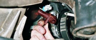
Location of the DPRV on the engine
To check the camshaft position sensor, you need to know where it is located. As a rule, on eight-valve engines the DPRV is usually mounted at the end of the cylinder head. On sixteen-valve engines it is also mounted on the cylinder head, usually in close proximity to the first cylinder.
As for popular domestic VAZ cars, their owners call such units phase sensors. Their location in these motors is similar. So, on eight-valve engines, the sensor is located on the left side of the cylinder head (when viewed in the direction of travel of the car).
On sixteen-valve engines - on the right front part of the engine. In the latter case, the sensor is not directly visible visually; its location can only be assessed by the signal and power wires suitable for it. The VAZ 2114 phase sensor is fixed in close proximity to the air filter, near the cylinder head.
The essence and principle of operation
The camshaft sensor on the VAZ 2114 (phase sensor) is designed to generate pulse signals based on information about the engine operating cycle. It is located on the engine in the cylinder head area, near the air filter in the 8-valve version and on the drive camshaft near the generator in the 16-valve version.
The device is an element of on-board engine control and is installed exclusively on injection engines. It is found in all VAZ 2114 that comply with EURO-3 and have sequential injection of the fuel mixture.
The phase sensor design consists of:
- Sensitive part.
- Signal converter.
The second includes:
- Bridge circuit.
- Open collector output stage.
- Operational amplifier.
The operation of the sensitive element is based on the Hall principle. It is a circuit that captures magnetic field fluctuations. When the microcircuit receives a signal, and this happens when the valve head, which is a magnetically conductive material (steel), passes by it, it transmits the signal further through the device. The information received is analyzed by the on-board system of the machine and, based on the received data, controlled injection occurs.
Methods for checking the camshaft sensor
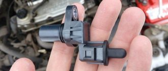
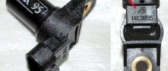
Before testing the sensor using a multimeter or other electronic tools, you must check its mechanical integrity. In particular, it is installed in a housing with an O-ring, ensuring its secure fastening. We need to check its condition.
It would also be useful to check the integrity of the sensor body, whether there are cracks or other damage on it. It is advisable to check the drive disk to see if the teeth are damaged or if there are metal shavings on the sensor body or nearby.
On the Internet you can find information that supposedly the DPRV can be determined to work by simply checking its magnetic properties. In particular, bring a small metal part to its end (the working sensitive part), which should “stick” to the sensor. In fact, this is not the case , and a non-working DPRV may or may not have magnetic properties. Accordingly, verification must be performed using other methods.
There are two main ways to test the camshaft position sensor - using an electronic multimeter and using an oscilloscope. The first method is simpler and faster, but the second is more accurate and provides more diagnostic information.
Checking the camshaft sensor with a multimeter
To check the DPRV, dismantling is necessary. This is not difficult to do; you just need to disconnect the contact group of wires from it and unscrew the fastening bolt. You will also need a small metal object (ferrous metal so that it is magnetic) to test.
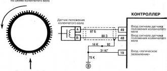
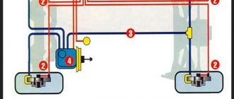
Connection diagram for checking phase sensor 21110-3706040.
Connection diagram for checking phase sensor 21120-3706040 The algorithm for checking the sensor with a multimeter is as follows:
- Take a multimeter and switch it to the DC voltage measurement mode in the range up to 20 V (depending on the specific multimeter model).
- Disconnect the “chip” from the sensor by unclipping the latch.
- Remove the sensor from its mounting location.
- On the “chip” of the sensor 21110-3706040 of a VAZ car (and on many others), contact “A” corresponds to ground, contact “C” is the positive wire, comes from the control relay, contact “B” is the signal wire (middle). For sensor chip 21120-3706040, contact “A” corresponds to ground, contact “B” is the positive wire from the control relay, contact “C” is the signal wire.
- Check the presence of power on the chips. To do this, you need to turn on the ignition on the car (but do not start the engine) and do this with a multimeter. If there is no power to the chips, then you need to look for the reason. This could be faulty wiring (insulation damage, broken wires), failure of the control relay, or a glitch in the electronic control system (ECU).
- Next, you need to connect the sensors for testing according to the diagrams shown in the figure.
- Apply a voltage of 13.5±0.5V to the sensor (although less is allowed, for example, 12...12.5 Volts from the battery).
- If, when power is applied to the sensor, the voltmeter detects a lack of voltage on the sensor, then this indicates either a breakdown of the sensor itself, the test can be completed and you can prepare to replace the sensor with a new one.
- Measure the voltage between the positive and signal contacts. It must be equal to at least 90% of the supply voltage (that is, if the supply voltage is 12 Volts, then the voltage at the signal contact must be at least 10.8 Volts).
- Bring a metal object prepared in advance to the end of the sensor (its signal part). Re-measure the voltage at the signal contact. It should be no more than 0.4 Volts. Remove the plate - the voltage value should be restored to 90...100% of the supply. If there are any deviations during the verification process, it means that the sensor has failed and must be replaced.
Please note that it is advisable to check not only sensors already installed on the engine, but also newly purchased ones, since there is always a risk of purchasing a defective product.
An electronic oscilloscope helps to understand how the camshaft position sensor works and whether it produces pulses at all. Usually they use a so-called electronic oscilloscope, that is, simply a simulator program installed on a laptop or other similar device. You need to connect to the camshaft sensor and take an oscillogram from it.
Ideally, there should be a smooth comb diagram with one drop-out peak that corresponds to the rapper passing through the sensor. If the oscillogram has a different shape, additional verification is needed.
When diagnosing the camshaft sensor of Nissan cars (in particular, Nissan Almera) with an oscilloscope, the shape of the oscillogram will be different. It will not be smooth, but in the form of 3 impulses, then a space, then 4 impulses - a space, 2 impulses - a space and one impulse - a space. For engines from this automaker, this feature is the norm.
How to check the phase sensor on a VAZ 2114?
Before checking the VAZ 2114 phase sensor with a multimeter, you must first inspect the part for damage. If there is visible mechanical damage to the product body, it must be replaced with a known working one. If there are no cracks or chips, diagnostics are carried out in the following order:
- Remove the phase sensor from the car. To do this, disconnect the electrical connector and unscrew the fasteners securing the products in the seat. To speed up the process, you can use a ratchet head.
- The multimeter switch is set to DC voltage measurement mode. For testing, select a range of up to 20 volts.
- Measure the voltage at the positive and negative contact pads of the electrical connector. With the ignition on, the multimeter should show the presence of constant voltage.
- Connect the positive and negative contacts to the battery. At the same time, the voltage applied to the part is measured. It should be between 12-14 volts.
- The multimeter is connected to the positive and signal pads, and readings are taken. The voltage between the positive signal contact must be at least 90% of the supply voltage.
- Bring a metal plate to the working surface of the part. As the plate approaches, the voltage should drop to 0.4 volts.
If during diagnostics it turns out that the DPRV has failed, it must be replaced with a new sensor. Otherwise, you should pay attention to the integrity of the electrical wiring. If necessary, clean the connector pads from oxidation.
Replacing the camshaft position sensor
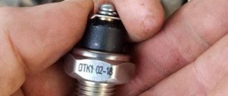
If during the inspection it turns out that the camshaft position sensor itself has failed, then it must be replaced. As a rule, these units are non-repairable, since their body is sealed and cannot be disassembled. The sensor is inexpensive, and the replacement procedure is simple, and even a novice car enthusiast can handle it.
The sensor replacement algorithm is as follows:
- With the engine not running, disconnect the negative terminal from the battery.
- Disconnect the “chip” from the camshaft position sensor (as when checking).
- Depending on the vehicle model, it is necessary to remove parts that prevent access to the sensor. For example, on modern cars like the Lada Vesta, it is necessary to remove the bracket for auxiliary units.
- Using a wrench, unscrew one or two mounting bolts, depending on the type of fastening. The size of the wrench can be different, usually for VAZs it is a 10 mm wrench.
- After dismantling the mount, you must similarly remove the sensor from its seat.
- Installing a new sensor is performed in reverse order.
- Connect the negative terminal to the battery.
When purchasing a new camshaft position sensor, you need to pay attention to the condition of its O-ring. It is usually sold separately. When changing the sensor, it is advisable to also change the O-ring, since over time it wears out and loses its elasticity. You can use an old ring only in case of emergency, when it is not possible to buy a new one.