Engine design features
Cars of the LADA SAMARA-2 family are equipped with an engine mod.
2111 - gasoline, four-stroke, four-cylinder, in-line, with a fuel injection system, with a camshaft located in the cylinder head. It is based on the mod engine. 21083. Engine cylinder operating order: 1–3–4–2. The engine is specifically designed for transverse mounting in a front-wheel drive vehicle. The layout and main dimensions of the engine are chosen so that it, together with the gearbox, can be placed transversely in the engine compartment between the body mudguards.
The power unit - an engine with a gearbox and clutch - is mounted in the engine compartment of the car on three rubber-metal supports.
4.1. Longitudinal section of a VAZ-2111 engine
4.2. Cross section of a VAZ-2111 engine
The cylinder block is cast from special high-strength cast iron, which gives the engine structure rigidity and strength. The cylinders are made integral with the block. At the bottom of the cylinder block there are five main bearing supports with removable caps. The main bearing caps are bolted to the cylinder block. The holes for the bearings are machined together with the covers, so the covers are not interchangeable and are marked with marks on the outer surface to distinguish them. The middle support has two sockets for thrust half-rings that hold the crankshaft from axial movements. A steel-aluminum half-ring is installed in front of the main bearing cap, and a cermet half-ring is installed at the rear so that the grooves on the half-rings face the crankshaft. The main and connecting rod bearing shells are thin-walled steel-aluminum. The upper main bearings of the first, second, fourth and fifth supports are with grooves on the inner surface, the lower main bearings and the upper bearing of the third bearing are without grooves. The inner surface of the connecting rod bearings is smooth, without grooves.
The crankshaft is made of high-strength cast iron and has five main and four connecting rod journals. To reduce vibrations, eight counterweights located on the crankshaft are used. To supply oil from the main journals of the crankshaft to the connecting rods, oil channels are drilled in the crankshaft and closed with plugs. In addition to supplying oil to the crankpins of the crankshaft, these channels also serve to clean the oil. Centrifugal force forces solid particles and resins that are not captured by the oil filter element to be thrown towards the plugs.
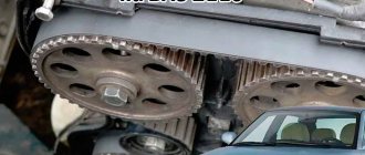
4.4. Camshaft drive diagram:
1 – crankshaft toothed pulley; 2 – toothed pulley of the coolant pump; 3 – tension roller; 4 – rear protective cover; 5 – camshaft toothed pulley; 6 – toothed belt; 7 – tension roller axis; A – installation ledge on the rear protective cover; B – mark on the camshaft pulley; C – mark on the oil pump cover; D – mark on the crankshaft pulley
At the front end of the crankshaft there is a drive gear of the oil pump, and on the segment key there is a toothed pulley 1 (see Fig. 4.4) to drive the camshaft and water pump. In addition, a generator drive pulley or damper is installed at the front end of the shaft. A flywheel is attached to the rear end of the crankshaft with six bolts through a common washer. It is cast from cast iron and has a pressed steel ring gear designed to start the engine with a starter. The connecting rods are steel, I-section, machined together with the covers. The cylinder number is marked on the connecting rod cap and the connecting rod itself. A steel-bronze bushing is pressed into the upper head of the connecting rod. The piston pin is steel, tubular section, floating type. It is secured against longitudinal movement by two retaining spring rings located in the grooves of the piston boss. The piston is made of aluminum alloy. On the bottom of the piston there is a recess for the combustion chamber and two recesses for the valves. The piston skirt is conical in longitudinal section and oval in cross section. In the upper part of the piston there are three grooves machined for piston rings. There are drillings in the groove of the oil scraper ring that serve to drain the oil collected by the ring from the cylinder walls into the piston. The piston rings are located in the grooves of the piston. The two upper rings are compression. They prevent gases from breaking through into the engine crankcase and help remove heat from the piston to the cylinder. The lower ring is an oil scraper ring.
4.3. Valve drive mechanism:
1 – cylinder head; 2 – valve; 3 – pusher; 4 – camshaft bearing housing; 5 – camshaft; 6 – adjusting washer; 7 – oil deflector cap; A – gap between the cam and the adjusting washer
Cylinder head 1 (Fig. 4.3), common to all engine cylinders, is made of aluminum alloy. The head is centered on the cylinder block by two bushings and secured with bolts. At the bottom of the head, channels are cast through which liquid circulates, cooling the combustion chambers. In the upper part of the head there is a camshaft 5, which rotates in supports made in the upper part of the block head and two bearing housings 4, secured with nuts on studs screwed into the block head. The camshaft is cast from cast iron. To reduce wear, the working surfaces of the cams and the surface under the oil seal are heat-treated - bleached. The camshaft cams operate the valves 2 through pushers 3. Steel adjusting washers 6 are installed in the upper part of the pushers; by selecting these washers, the clearances in the valve drive are adjusted.
The camshaft is driven from the crankshaft toothed pulley 1 by a rubber toothed belt 6 through the toothed pulley 5 (Fig. 4.4). The belt tension is adjusted by tension roller 3. A metal-reinforced gasket made of non-shrinking material is installed between the head and the cylinder block.
The cylinder head is equipped with eight valves - two valves per cylinder (one intake and one exhaust). The valves close under the action of two springs. The lower ends of the spring rest on the support washer, and the upper plate of the springs is held by two crackers in the valve groove. The outer surface of the valve cotters has the shape of a truncated cone, and on the inner surface there are three thrust protrusions that fit into the corresponding grooves of the valve stem.
The guide bushings and valve seats are pressed into the cylinder head. Lubrication channels are cut on the inner surface of the bushings. Oil reflective caps 7 are installed on the guide bushings to prevent oil from entering the cylinders. The guide bushings are secured with retaining rings.
Lubrication system:
1 – channel in the cylinder block for supplying oil to the oil line of the cylinder head; 2 – channel in the cylinder head; 3 – pipe for exhausting crankcase gases into the air filter housing; 4 – oil filler cap; 5 – exhaust hose pipe; 6 – pipe for removing crankcase gases into the throttle space of the carburetor; 7 – oil line in the cylinder head; 8 – camshaft; 9 – oil supply channel to the camshaft bearing; 10 – oil pressure warning lamp sensor; 11 – pressure reducing valve; 12 – channel for supplying oil from the filter to the main oil line; 13 – drive gear of the oil pump; 14 – driven gear of the oil pump; 15 – oil supply channel from the pump to the filter; 16 – anti-drainage valve; 17 – cardboard filter element; 18 – oil sump; 19 – oil receiver; 20 – drain plug; 21 – bypass valve; 22 – oil filter; 23 – oil supply channel from the crankshaft main bearing to the connecting rod; 24 – oil supply channel to the crankshaft main bearing; 25 – main oil line
Combined lubrication system: splash and pressure. The system consists of an oil sump 18 (Fig. 4.5), a gear oil pump with an oil receiver, a full-flow oil filter, an oil pressure sensor 10 and oil valves. The main and connecting rod bearings, as well as the camshaft bearings 8, are lubricated under pressure. Oil is sprayed onto the cylinder walls and then to the piston pins and rings, as well as to the camshaft cams, valve lifters and to the intake and exhaust valve stems. Gear-type oil pump, with 14 driven and 13 driven internal gears. The pressure created by the pump is regulated by pressure reducing valve 11. Oil receiver 19 is bolted to the second main bearing cover and the pump housing. Oil filter 22 is full-flow, non-separable, with bypass 21 and anti-drainage valves, with a cardboard filter element 17.
WHICH GDP IS BETTER TO CHOOSE?
When choosing a GDP, two key factors must be taken into account - their resistance and breakdown voltage. The lower the resistance, the better the electrical impulse will be transmitted, and the magnitude of the maximum breakdown voltage determines how resistant the high-voltage wires on the VAZ 2114 will be to breakdowns.
The resistance value of products from different manufacturers differs from each other. As an example, we give you the resistance of the most popular types of GDP:
| Manufacturer | Resistance on cylinder No. 1 (kOhm) | Resistance on cylinder No. 2 | Resistance on cylinder No. 3 | Resistance on cylinder No. 4 | Breakdown voltage (kV) |
| Tesla | 3.27 | 4.16 | 5.02 | 6.26 | 50 |
| Cezar | 3.1 | 3.53 | 4.23 | 5.34 | 50 |
| Finwhale | 1.95 | 2.18 | 2.6 | 3.42 | 50 |
| Ween | 6.17 | 6.57 | 7.52 | 9.89 | 35 |
| Slon | 4.24 | 4.74 | 5.19 | 7.6 | 50 |
The products of the Czech company Tesla receive the largest number of positive reviews from the owners of the fourteenth. Their wires have optimal resistance and high breakdown voltage, and at the same time they are truly made to last - they do not tan or crack.
The cost of the Tesla GDP set is about 500 rubles, Cezar – 450 rubles, Ween – 270 rubles, Finwhale – 600 rubles, Slon – 500 rubles.
CONNECTION FEATURES
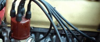
The order of connecting high-voltage wires must be strictly sequential, since each cylinder of the engine corresponds to a specific socket on the ignition module. Considering that there is a numbering of the sockets on the ignition module body, the risk of confusing anything is minimal.
The procedure for connecting high-voltage wires of the VAZ 2114 injection type depends on the year of manufacture of your car. Fourteeners before 2004 had 4-pin ignition modules installed, and cars after 2004 had 3-pin coils.
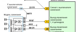
The connection diagram for VAZ 2114 high-voltage wires to the ignition module (until 2004) is as follows:
Connection diagram for VAZ-2114 with ignition coils (after 2004):
In the pictures you can see the numbers of the landing slots. Each number must have a corresponding cylinder connected to it (cylinder numbering is counted from left to right).
To correctly install high-voltage wires on the VAZ 2114, follow the following algorithm of actions:
- Turn off the ignition. Open the hood and remove the power terminals from the battery;
- We remove the old GDPs from the mounting sockets on the module and cylinders;
- We remember the location of the high-voltage wires of the VAZ 2114 and connect new GDPs according to the diagram. Before replacing, it would not be amiss to draw this very diagram by hand on paper so as not to confuse anything;
- We connect power to the battery and, to check whether we did everything correctly, start the engine.
When installing the wiring, do not try to connect individual air intakes to each other with plastic clamps; to do this, you must use the comb holder that comes with them. A thin clamp can easily wear through the insulating coating. Also make sure that the GDP does not bend.
Connecting armored wires on VAZ 2115 and 2113 is carried out in a similar way.
BB: professional replacement
If you have decided to contact the service for the process of replacing high-voltage wiring, then it is, of course, a good thing, but not worth the money that will be asked of you. They can also confuse your brain on the topic of how often high-voltage wires need to be changed, with the logic that it is better to take care of prevention in advance than to get stuck on the highway. You won’t get stuck on the highway, the contact is not a sensor, even the last one doesn’t die right away. Replacement will cost from 1000 rubles. The advantage of service in this case will be the fact that they will look at the candles for you. And they will definitely be cleaned (they tend to become oily, which negatively affects the throughput for pulses through high-voltage wires).
To avoid mixing up the wires, it is best to change them one at a time.
It is best to replace high-voltage wires as a set at once.
Disconnect one end of the wire from the spark plug.- Disconnect the second end of the wire from the ignition coil.
- Using a multimeter we measure the resistance of the wires.
- If the wire is in good condition, then the resistance on it will be in the range of 3.5-10 kOhm.
- We connect new wires to the spark plugs and coil. On the wire is the number of the cylinder to which it needs to be connected.
HOW OFTEN SHOULD I CHANGE GDP?
According to the recommendations of Avto-VAZ, replacement of high-voltage wires of the VAZ 2114 should be done every 30 thousand kilometers. In practice, motorists rarely comply with these replacement deadlines, since if the wires do not have any mechanical damage, they can travel about 100-150 thousand km.
When the service life is exceeded, the internal resistance of the GDP increases, which negatively affects the transmission of the electrical impulse. This leads to problems with ignition and acceleration dynamics, since when the supply of current to the spark plugs is delayed, the normal engine operating cycle is disrupted.
Change the wires every 25-30 thousand km and everything will be fine
Video “The principle of operation of internal combustion engines”
This instructional video explains how the combustion system works.
Many motorists, especially beginners who have just purchased a VAZ-2114, have wondered how the 8-valve injection engine that is installed on this car works. This article will discuss the design of the motor, its main characteristics, as well as dismantling and repair features. This information will be very useful for beginners and those who do not know how the main power unit works.
Video about the VAZ-2114 engine
OPERATIONAL CHECK
To accurately determine whether it is time to change the high-voltage wires of the VAZ, you need to check their performance with a multimeter.
This operation will take you no more than 15 minutes:
- Turn off the ignition;
- We remove the wires: disconnect the first end from the ignition module, the second from the cylinder;
- We switch the tester to ohmmeter mode and connect the multimeter probes to the wire contacts.
If the high-voltage wires on the VAZ 2114 are in normal technical condition, the multimeter will show a resistance within the value indicated on the wire insulation; if the readings are different, the armored wires on the VAZ 2114 need to be replaced. The process must be repeated on each wire in turn.
If the test shows disappointing results, there is a possibility that the problem of increased resistance lies in oxidized contacts. In this case, you can try to revive the VVP by wiping the contacts with VD-40 or carburetor cleaning fluid.
Also, the cause of problems with ignition can be a breakdown of the GDP. You can determine it visually in the dark - take a flashlight and open the hood of the fourteenth, find and inspect the armored wires, if you notice a slight spark on the insulation - the air intakes are broken and need to be replaced.
BB: replacement
We remind you once again that before making a replacement, the high-voltage wires on the VAZ 2114 are usually tested. This will help you avoid unnecessary expenses and make sure that they are faulty.
Before you begin removing high voltage contacts, do the following:
- The car must be with the ignition turned off
- Open the hood
- Carefully disconnect all contacts from the ignition coils and the engine itself (just in the place where the wires supply the impulse to the VAZ 2114 spark plugs).
By the way, despite the obvious malfunction of the high-voltage wiring, often the cause of poor performance is oxidation of the area where the ends of the wiring meet. For prevention, it is advisable to wipe everything with WD. Many people try to revive the state of their wiring in this way, but attempts, although they sometimes bring results, are futile. You will increase the service life of high-voltage equipment by just a little bit. They cannot be rehabilitated, only replaced with new ones.
Now we take the new wiring and put it in place with the same accuracy as before:
- We remember the diagram of the position of the wires or put it next to us
- Or you sketched how it was before your intervention, it doesn’t matter, the main thing is to follow the installation order in the way you need it!
Otherwise, you risk burning out the engine and spending money on almost a new car.
Engine VAZ-2115
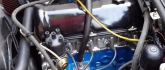
The VAZ-2115 has a gasoline engine, four-cylinder, in-line, four-stroke, with an overhead camshaft, eight-valve. The cylinders operate according to the following scheme: 1–3–4–2, counting from the crankshaft pulley. The system is powered through electrically controlled distributed fuel injection.
Fig.1 VAZ 2115 car engine
- coolant supply pipe;
- engine cylinder complex;
- thermostat;
- coolant temperature sensor;
- outlet pipe;
- engine cylinder head plug;
- engine cylinder head cover;
- fuel pressure level regulator;
- oil filler cap;
- throttle cable;
- throttle assembly;
- idle air control;
- throttle position sensor;
- receiver;
- rear cover of the gas distributor drive;
- front cover of the gas distributor drive;
- injector;
- fuel rail fitting plug;
- fuel ramp;
- intake manifold;
- right intake manifold support bracket;
- generator drive pulley;
- Oil filter;
- crankshaft position sensor;
- oil pan;
- intake manifold;
- connecting rod;
- crankshaft;
- intake manifold support bracket left;
- flywheel.
The engine, together with the clutch and gearbox, form a power unit in the engine compartment - a block on three rubber-metal supports.
The cylinder block is made of cast iron. The nominal diameter is 82 mm, it can be increased by 0.4 or 0.8 mm during repairs. The cylinder class marking is marked on the bottom plane in Latin letters according to the cylinder diameter in millimeters. The permissible level of cylinder wear is 0.15 mm per diameter.
The cylinder block contains five bearing supports, which are bolted to the block. The covers are not interchangeable, since the holes for the bearings are modified in the assembly with the covers. To distinguish them, they are marked on the outside with marks. Thrust half-rings in the middle support prevent axial displacement of the crankshaft.
There is a steel-aluminum half-ring installed in the middle, and a yellow metal-ceramic one at the back. In this case, their grooves face the crankshaft. If the crankshaft play exceeds 0.35 mm, the half rings should be replaced.
Thin-walled shells for connecting rod and main bearings are made of steel-aluminium. The main upper bearings of the first, second, fourth and fifth supports have a groove on the inner surface. The lower main bearing and the upper bearing of the third bearing are without grooves, just like the connecting rod bearings.
The crankshaft is made of high strength cast iron and has journals: main and connecting rod. The shaft has eight counterweights cast with the shaft. Oil is supplied from the main crankpins to the connecting rod journals through drilled channels. The channel entrances to the shaft cheeks are closed with plugs. The channels also serve for oil purification: the rotation of the crankshaft throws resins and solid particles towards the plugs under the influence of centrifugal forces. When dismantling the crankshaft, it is advisable, and before balancing it is simply necessary, to clean these channels from accumulated deposits. The plugs cannot be reused.
The principle of operation of a four-stroke power plant
You can understand why it is important to connect high-voltage wires correctly if you study the principle of operation of the power plant. The carburetor or injector of the VAZ-2109 operates on approximately the same principle, since both power plants are four-stroke.
- First, the cylinder volume is filled with the fuel mixture and exhaust gases. This process is called "inlet".
- The engine then goes into compression. With it, the valves are closed, and the crankshaft and connecting rod move the piston upward. The mixture of fuel and air is transferred to the combustion chamber.
- During the expansion stage, the ignition is switched on and a spark appears. It ignites the fuel mixture, resulting in the formation of gases. They put pressure on the piston, causing it to move down. This force is transmitted through the connecting rod to the crankshaft.
- The process is completed by the “release” of exhaust gases through the exhaust system.
In order for the engine to operate smoothly and without jerking, the processes must take place in a certain order. This, first of all, concerns the order in which the cylinders are put into operation.
Engine workflow through cylinders
The cylinders are activated as follows:
- In the first there is an upward movement. The gases expand and the mixture of air and fuel burns.
- In the third, to carry out the compression procedure, the piston rises.
- In the fourth, “injection” occurs - the piston moves down and at the same time a mixture of air and gasoline enters the cylinder.
- In the second cylinder, the piston rises and takes the upper position so that gases escape through the valve system. After which the exhaust gases are removed from the power unit.
Based on the principle of operation of the cylinders, their activation diagram looks like this: 1-3-4-2. It is important to connect them correctly so that the cylinders work in that order.
The operating order of the VAZ 2106 cylinders: diagram, photo, video instructions
Much depends on the operation of the cylinders, so this unit must always be in working condition. Especially when it comes to old VAZ 2106 cars. In this article you can find out what is the operating order of the VAZ 2106 cylinders and for what reasons they may not work.
Work distribution
It may be necessary if it is necessary to identify a malfunction in the operation of the motor. Such breakdowns consist of unstable engine operation, that is, its tripping. It is necessary to diagnose the unit in cases where the engine power is too low, and the internal combustion engine itself regularly trips.
It should be added that the internal combustion engine throttles not only when driving at speed, but also in neutral gear. In addition to tripping and reduced power, fuel consumption in the vehicle increases. This sign is initial. In practice, interruptions in the operation of the power unit are observed when the carburetor is incorrectly adjusted, the spark plugs are broken, or one of the cylinders fails. In addition, air may leak into one of the cylinders.
But in order to accurately identify the malfunction, you need to know the operation of the cylinders in the vehicle. In a VAZ 2106 car it is as follows: 1-3-4-2. Accordingly, the numbers directly indicate the numbers of the cylinders themselves. The number “1” on the distributor cap is marked on the first cylinder. If you look at its cover from the side of the wires leading to the spark plugs, the cylinder operating mode will be 1-3-4-2.
How to connect wires correctly
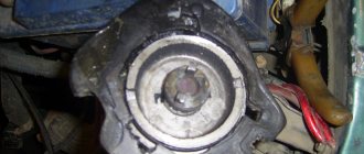
When replacing high-voltage conductors, they are first connected to the ignition distributor. The distributor cover is convenient in that it is always installed in one position. There is a special mark on it, thanks to which it will not be difficult to place the part in place. Before connecting the wires, inspect the cover. It must be intact, since if cracks appear, the performance of this unit is not guaranteed.
The mark on the distributor cover is located next to the wire socket of the first cylinder. The firing order of the cylinders is slightly out of order (1-3-4-2) due to the ignition slider. It moves around the circle (distributor) counterclockwise. It is precisely by this principle of movement of the slider that it is easy to remember the order of the wires. They need to be connected to carburetor and injection VAZ-2109 according to the same principle. On the distributor cover, connect the wires according to the principle of movement of the slider, this is the only way you can set the ignition correctly:
- the socket of the first cylinder is located at the mark;
- the third one is connected at the very bottom;
- on the same line with the socket of the first, there is a place for the wire to the 4th cylinder;
- at the top point the second cylinder is connected.
On the engine itself, the cylinder numbering goes from the location of the timing belt to the starter, that is, from left to right. The fourth cylinder is closest to the starter, and the first is closest to the timing belt. When connecting, it is important to look at which socket of the distributor cover the wire comes from, if you confuse their location, the car will not start.
If you have connected the wires correctly, but the car still does not start, then the problem may be in them. Check high-voltage conductors for integrity. If you haven't changed them in a while, it's worth buying a new set. The peculiarity of these wires is that over time microcracks can form on their surface. They lead to a lack of spark when the ignition distribution system is working. Moisture and dust get into these cracks, which damages the wire from the inside, although it appears intact from the outside.
How to set the ignition
In order to correctly adjust and set the ignition on a UAZ, you must follow the sequence of actions that are given in the user's repair manual.
Before you begin adjusting the ignition system, you must place the vehicle on an inspection pit or a special platform for repair work and apply the hand brake. The wheel mechanisms of the vehicle must be secured with a stopper or stop. The power unit must be turned off.
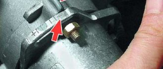
After this, you can begin installing the ignition. To do this, it is necessary to fix the piston of the first cylindrical element in the position of the highest dead center. In this case, you need to check that the hole on the crankshaft pulley coincides with the pin on the cover of the timing gear block. It is necessary to slightly lower the mounting bolt located on the plate to the distribution equipment sensor housing.
Then remove the cover from the distributor and rotate the crankshaft 180°. The octane corrector must be in the zero position. Then it is necessary to tighten the pointer to the housing of the distribution mechanism sensor with a bolt so that its position coincides with the octane corrector mark.
After this, we adjust the slider by rotating it counterclockwise. This will help eliminate gaps in the drive. When the tip on the stator coincides with the red mark, you can fix the plate with a bolt.
Then you need to replace the switchgear sensor cover and check that the ignition leads are installed correctly according to the operating order of the cylindrical mechanisms (1-2-4-3). You need to count in a counterclockwise direction. The ignition setup on the UAZ is completed.
Now it is recommended to start the power unit and warm it up to operating temperature (about +80°C). Then you need to sharply press the accelerator at a speed of 40 km/h on a straight section of the road.
In case of severe detonation, it is recommended to turn the distributor sensor 0.5-1 turn on the octane corrector scale in a counterclockwise direction.
If there is no detonation, you need to increase the advance angle by turning the sensor clockwise.
How to check high-voltage wires of a VAZ 2110
how to check the high-voltage wires of the ignition system.
Diagnosis of misfires on VAZ cars.
High-voltage wires of engine 2112 (1.5i 16v) - check and replacement.
Ignition coil with wires VAZ 2110 BU.
High voltage wires 8kl. injector VAZ 2111 SLON.
procedure for connecting high-voltage wires VAZ 2110 injector Do it yourself.
AT 320N Wiring for VAZ 2110 (1.5i 16V).
Removal, installation and repair of Lada Granta ignition coils
How to install high-voltage wires correctly.
Checking and replacing spark plugs of the VAZ 2110 Lada.
High-voltage wire VAZ-2111 dv.1.5 SLON set.
ignition module 2112-3705010-02 -2110.
2111-3707080 SLON High-voltage wire VAZ-2110 SLON kit (packed)…
Spark plugs for VAZ 2110 8 valves.
How to check the high-voltage wires of a car?
VAZ 2110 (VAZ 2110) – Replacement of I/O ignition wires.
Diagram, procedure for connecting VAZ high-voltage wires.
The numbering of the wires is marked on white rings, and the qi numbers are cast on the module...
VAZ 2110 (VAZ 2110) – Replacement of I/O ignition wires.
Replacement of high-voltage wires and installation of the left rear view mirror, i.e...
Comment on Removing and disassembling the ignition sensor-distributor of the VAZ-2110.
High-voltage wire VAZ-2112 V16 silicone set, RF.
How to connect the ignition switch
Replacing the ignition switch involves dismantling the old one and installing a new mechanism with its subsequent connection. To remove the old lock you will need a Phillips and flathead screwdriver.
The procedure for dismantling the old vehicle ignition system lock:
- Remove the fasteners from the lower trim panel of the steering column.
- Insert the key into the lock and set it to the zero position, at which the steering mechanism will be locked.
- Remove the steering column.
- Unscrew the ignition switch mounting bolts.
- Insert a flat-head screwdriver into the small technological hole and press the latch that holds the lock.
- Push the lock out of its seat.
- Disconnect all system wires.
- Install a new lock, connect the wires and reassemble the mechanism, performing all the steps in reverse order.
All wires are connected in a clockwise direction.
To terminal number 50 you need to connect a red wire, which is responsible for the stable operation of the starter device.
To terminal number 15 you must connect a blue wire with a black stripe, which is responsible for heating the vehicle interior.
A pink wire is connected to pin number 30, and a brown wire is connected to 30/1.
The black wire must be connected to the INT connector, which is responsible for the operation of the side lights and headlights.
After all the wires are connected, you need to connect the battery terminal. A black wire should be connected to the top of the terminal. Then you need to start the engine and check the serviceability and functionality of the entire ignition system. First, it is recommended to check the operation of electrical devices, and then the serviceability of the starter mechanism.
If all wires are connected correctly, then when the ignition system key is in the zero position, all elements of electrical equipment will be disconnected from power. When the key is turned to the first position, the system is activated, which controls the internal combustion engine, generator set, headlights and brake lights, as well as washers and windshield wipers. When the key is moved to the second position, the starter is activated, the anti-theft system rod extends and retracts when the key position is changed.
If this does not happen, it means the wires are connected incorrectly. It is necessary to disassemble the mechanism and repeat the connection procedure.
Ignition circuit for VAZ 2109
Every owner of the VAZ 2109 should know the ignition circuit Without knowing this circuit, you will not be able to start the car in case of ignition problems. Moreover, this scheme is elementary simple. The VAZ 2109 is equipped with a contactless ignition system. It consists of the following components: switch, ignition coil, distributor, Hall sensor, high-voltage wires and spark plugs. The task of the ignition system is to provide a timely, cyclic spark to the engine cylinders. Let's take a closer look at how the clamping circuit works.
Ignition circuit for VAZ 2109
ignition of the VAZ 2109: power is supplied to the ignition system through a relay. Until the key is in the ignition position, the relay will not turn on and supply power to the circuit. As soon as the key is turned, the ignition system is energized. +12V power from the battery is supplied to contact B of the ignition coil, the 4th contact of the switch. The Hall sensor powers the switch itself. Please note that the ignition relay is powered through the mounting block, and if there is poor contact in connectors Ш1, Ш8 or for some reason the track oxidizes or burns out, the ignition system will not be powered and the VAZ 2109 will not start. In order for a spark to begin to form, you need to crank the engine crankshaft. Together with it, the camshaft will turn and the Hall sensor will send an impulse to the switch. The commutator, in turn, will connect contact K of the ignition coil to ground, resulting in a spark appearing on the central wire. When the distributor slider connects the central wire and the wire leading to a specific engine cylinder, a spark will jump on the spark plug, igniting the combustible mixture. The engine will start. When it is necessary to turn off the engine, the driver, by turning the key in the ignition switch, turns off the relay, which in turn disassembles the power supply to the system. The switch and ignition coil become de-energized and stop working. The most common malfunctions of the VAZ 2109 ignition system: 1) Failure of the switch. 2) Failure of the Hall sensor. 3) Poor contact of the slider in the distributor. 4) Lack of power supply to the ignition system of the VAZ 2109. Go to Home.
Car ignition installation procedure
Construction machines and equipment, reference book
Category:
Car device
The ignition is installed to ensure normal operation and obtain the greatest power and efficiency of the engine. It is carried out if the ignition distributor is removed from the engine or if the ignition timing is not set correctly.
Installing the ignition on a GAZ-66 car in case of removing the ignition distributor is carried out in the following order: 1. Set the piston of the first cylinder to a position 4° before TDC on the compression stroke according to the marks on the flywheel and the arrow in the flywheel housing window. To determine the compression stroke, it is necessary to unscrew the first cylinder.2. Set the octane corrector to “O”, check the condition of the breaker contacts and the gap between them, and adjust if necessary.3. Insert the ignition distributor so that the vacuum regulator is directed upward, and by turning the drive shaft, insert the shank into the groove of the drive shaft.4. Using a screw, secure the fixed octane corrector plate to the drive housing and connect the wire to the distributor terminal.5. Loosen the nut securing the drive housing holder and turn the distributor housing to set the breaker contacts to the beginning of opening. It is better to determine the beginning of the opening of the contacts by the control light, for which connect it between the breaker terminal and ground (on cars with a contact-transistor ignition system, connect it between the unmarked terminal of the ignition coil and ground). Then turn on the ignition and, if the control lamp lights up, turn the distributor housing clockwise until the lamp goes out, and then slowly turn the distributor housing counterclockwise until the lamp lights up. In this case, the ignition distributor rotor must be located against the electrode with the number “1”.6. Tighten the nut securing the drive housing holder.7. Replace the distributor cap and connect the wire from the side electrode of the cap with the number “1” to the spark plug of the first cylinder. Connect the remaining wires to the spark plugs in the order of engine operation (1-5-4-2-6-3-7-8), following from electrode I clockwise.8. Connect the tube to the vacuum regulator.9. Check the correct installation of the ignition with the mileage of the loaded vehicle. To do this, on a flat road with a vehicle speed in direct gear of about 30 km/h, sharply press the throttle pedal all the way and hold it in this position until the vehicle speed reaches 60 km/h.
Rice. 1. Determination of TDC and setting the ignition on the ZIL-130 (ZIL-131) engine: 1 - crankshaft pulley; 2 — ignition installation indicator; I, II - ignition advance by 0° and 9°
If the ignition is installed correctly, during acceleration of the car, a slight detonation will be heard, which disappears when a speed of 40-50 jcm/h is reached. In case of strong detonation, it is necessary to move the index arrow of the upper plate of the octane corrector towards the “—” sign, and in the absence of light detonation, the index arrow must be moved towards the “+” sign. After adjusting the ignition timing, check the engine operation again using the vehicle's mileage.
The ignition installation on ZIL-131 and Ural-375D vehicles has features, the main ones of which are the following: 1. The piston of the first cylinder is installed in the compression stroke 9° before TDC with a contact ignition system and 6° before TDC with a transistor ignition system. Marks for setting the ignition are made on the engine crankshaft pulley (hole) and on the ignition setting scale.2. With a transistor ignition system, instead of installing contacts at the beginning of opening, it is necessary to rotate the distributor body to align the installation (red) marks on the rotor and stator of the pulse sensor and tighten the bolt securing the octane corrector plate to the distributor body.3. The spark plug wires are numbered, which makes it easier to distribute them among the cover sockets.4. On the Ural-375D vehicle, the ignition installation is not checked by mileage.
Read more: Main malfunctions of the ignition system and methods for detecting the causes of malfunctions
Category: – Car structure