How to check if the battery is charging
Before looking for a fault in the charging circuit, it is necessary to find out whether this very undercharging actually exists. After all, the problem could be:
- in charge indication circuits;
- in a faulty battery.
Healthy! To check, we use a DC voltmeter with a measurement limit of 20 V or a multimeter (tester). Both pointer and digital devices are suitable. The accuracy of both will be sufficient.
We connect a voltmeter or multimeter turned on in the DC voltage measurement mode to a limit of at least 20 V. We start the engine and raise its speed to 1,000 per minute. If the voltmeter shows a voltage in the range of 13.5-14.2 V, then the charging circuits are OK. The fault is with the charging indication elements that mislead us, or with the battery.
In the first case, we check the control circuits (their circuits and testing algorithm will be described below), in the second case, we test the battery using a load fork.
Charging circuit diagram and typical problems
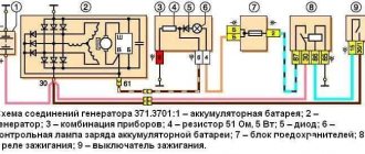
Before finding out why charging disappeared on the Niva VAZ 2121, 21213, 21214 injector, 2131 and 2123 (aka LADA Niva and Niva Chevrolet), let’s look at the circuit diagrams of the charging circuit of these models and the principle of their operation. Otherwise, you will have to search at random, and this is a bad method.
VAZ 2121
Let's start with the oldest, because age must be respected. Let's take a look at the diagram below.
The numbers on the diagram indicate:
- - accumulator battery;
- – generator with built-in rectifier bridge;
- – relay-regulator;
- – ignition switch (lock);
- – fuses in the mounting block;
- – indicator lamp for lack of charging;
- – warning lamp relay.
When the ignition switch is turned on, the voltage from the battery through the fuse and the normally closed contacts of the voltage regulator relay is supplied to the generator excitation winding. The relay regulator does not operate yet, since the voltage in the on-board network is below the normal level for charging. At the same time, through the second fuse, the same voltage is supplied to the battery charging control unit, assembled on an electromagnetic relay with normally closed contacts.
Since the generator is not producing anything yet, there is nothing at its middle point of connection of the windings - all the rectifier diodes are locked, it seems to be hanging in the air. As a result, the control unit relay also does not work and the “no charging” lamp is on.
Now we start the engine, the generator begins to generate voltage, which is rectified, charges the battery and powers the on-board network. At this time, at the connection point of the windings, which is essentially the neutral wire, a low potential is established relative to the positive wire of the on-board network. The relay is activated and extinguishes the control lamp.
The voltage level from the generator is monitored by a relay regulator. As soon as it exceeds the critical value (14.2 V), the relay will operate, its contacts will open and a reduced voltage will be supplied to the excitation winding, which means the voltage in the on-board network will also decrease. It becomes below normal (13.5 V), the relay will release again, and the process will repeat.
VAZ 21213, 21214, 2131, 2123
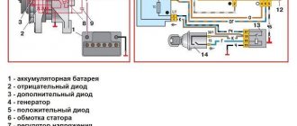
Now let's talk about other modifications of the Niva. All four remaining modifications of the car have the same charging circuit, shown in the figure below.
The numbers on the diagram indicate:
- - accumulator battery;
- – generator with built-in rectifier and relay regulator;
- – instrument cluster;
- – resistor;
- – diode switch;
- – indicator lamp for lack of charging;
- – fuse in the mounting block;
- – ignition relay;
- - egnition lock.
The schemes are very similar, but there are still differences. When the ignition is turned on, voltage from the battery is supplied to the ignition relay, and it is activated. The same voltage, through the normally closed contacts of the relay, is supplied to the charging control unit and from it to the relay-regulator as the initial bias of the excitation winding. An additional 12 V from the battery is supplied to the same relay-regulator built into the generator. In this case, the charging control lamp lights up, since its second output is connected to ground through an open diode and a small resistance (51 Ohms).
We start the engine, the generator rotates. The voltage it creates through additional decoupling diodes (on the left in the diagram) is supplied to the control output of the relay regulator. Based on this voltage, the relay-regulator controls the generator, changing the current in the excitation winding in one direction or another so that the voltage in the on-board network remains at the required level.
Important! The same voltage is applied to the cathode of the charge control diode. It locks and the light goes out.
Well, now let's talk about typical malfunctions of charging circuits and start, of course, with a false alarm that the charging control lamp can raise.
Engine Control Relay Box
| F1 (30A) | Right electric fan relay contacts |
| F2 (30A) | Left electric fan relay contacts |
| F3 (15A) | Relay windings of the right and left electric fans, controller, injectors, ignition coil |
| F4 (15A) | Heating elements for control and diagnostic oxygen concentration sensors, phase sensor, mass air flow sensor, canister purge valve |
| №1 | Ignition relay |
| №2 | Main relay |
| №3 | Right cooling fan relay |
| №4 | Left cooling fan relay |
| №5 | Fuel pump relay (fuel) |
| №6 | Fuel pump fuse F5, 15A |
On some vehicle versions, a starter relay may be located under the additional unit next to the ignition relay.
Warning lamp
Why can this light be on while charging is in progress? In the VAZ 21213 there is only one reason - voltage is not supplied from the additional diodes to the control unit. This may be due to a broken wire running from the 61st terminal of the generator to the 6th terminal of the instrument combination assembly or contamination of the connecting blocks. We inspect the connections, ring the wire.
In VAZ 2121 there are not much more reasons:
- the warning lamp relay is faulty;
- voltage (negative) is not supplied from the generator to the control relay.
We remove the relay, apply 12 V to its winding from the battery and check whether it works and whether the contacts are disconnected. Well, problems with the absence of negative voltage are still the same broken wire going from the generator to the relay, or poor contact in the blocks of this circuit. We call and clean the terminals.
Expert opinion
Alexey Bartosh
Specialist in repair and maintenance of electrical equipment and industrial electronics.
Ask a Question
Once again, we draw your attention to the fact that the above malfunctions relate to the control unit and do not in any way affect the normal charging of the battery.
The belt has stretched or broken
The drive belt for the generator and water pump from the engine shaft does not break very often, but it stretches regularly. As a result, it begins to slip on the pulleys, the generator, especially under load (high beams plus air conditioning, etc.), does not develop the required speed, and the voltage at its output drops. As a result, the battery is undercharged and may even be discharged, helping the “exhausted” generator and feeding the on-board network with its energy.
Poor belt tension is characterized by a drop in the voltage of the on-board network and a peculiar whistle when the speed increases sharply, especially in wet weather. The problem is treated quite simply. Find the generator mounting bolt on the tension bar. We loosen it, use a pry bar to move the generator to normal belt tension and tighten the bolt.
Expert opinion
Alexey Bartosh
Specialist in repair and maintenance of electrical equipment and industrial electronics.
Ask a Question
Healthy! An over-tightened belt is just as bad as a loose one. It can tear, leaving you spending the night on the road, and will very quickly stretch again. So you shouldn’t tighten the belt “for future use”. Its tension force should be approximately the same as indicated in the diagram below.
Three-level voltage regulator Niva 21214
Forum post, original.
And we have a generator KZATE 9412.3701 produced by OJSC (form of organization of a public company; joint-stock company) “Plant named after A.M. Tarasov” (OJSC (form of organization of a public company; joint-stock company) “ZiT”) with low (for modern batteries) regulation voltage .
Voltage regulation is carried out through additional diodes specially created for this purpose, while the output voltage and regulation voltage are equal only in the absence of overload. When overload occurs and it grows, the difference between these values increases proportionally.
Since 2004, the AvtoVAZ assembly line began to receive the latest generators for cars 2110, 2123, equipped with a new generation of voltage regulators. Regulators of the latest standard determine the voltage at the power terminal B+ of the generator, as a result of which they have a very clear idea of the voltage on the battery/on board. networks. The regulation voltage is at a level that is rational for modern batteries. In addition, they have a number of other advantages, but this is not particularly important to us. So, we will install such a regulator in our generator.
First, we will need to purchase a voltage regulator for the generator 9402.3701-03 or 9402.3701-04. The 2nd one is the best choice, because its body is compatible with our brush assembly boot. I bought a voltage regulator 941.3702 manufactured by OJSC (form of organization of a public company; joint stock company) “Avtoelektronika”, Kaluga.
Then, instead of the usual terminals on the voltage regulator, you need to install the ones shown in the photo above. Be sure to use terminals with the same hole diameters as I indicated, otherwise this is fraught with a short circuit.
Wiring and connections
One of the weakest points in the power supply circuit of the Niva (and any other car) is the connection of the power wire to the generator. The device is located low and is practically not protected from water and dirt. Even if this connection looks normal, it makes sense to disassemble it and inspect the contact point. We disassemble, inspect, clean if necessary, apply conductive lubricant, and assemble.
The next weak point is the connection of the negative wire of the battery to the engine. It is not located in the best place and is constantly dirty. As a result, the connection oxidizes and good contact is lost. We do the same thing: disassemble, clean, assemble.
It is also worth inspecting the terminals on the battery terminals. They may be oxidized (white coating) or loose. Clean, apply conductive lubricant, tighten.
Otherwise, the wiring and connections on the Niva behave quite correctly, but this does not mean that all this will last forever. Let's not be lazy, inspect the connections and wires. If necessary, we call.
Specificity of operation
The generator on the Chevrolet Niva works thanks to the effect of electromagnetic induction - when a moving electromagnetic field produces alternating current. The design has several coils that make the field. Also a receiver that removes electricity from them.
The relay regulator often breaks down. After a run of 100 or even 120 thousand km or more, this part has the risk of practically falling apart at any moment if it is not replaced in time. Relay regulator 2123 KZATE series C3, article number 845.3702, is suitable for replacement.
Problems with the generator
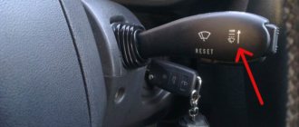
The most common malfunction of this unit is brush wear. At the initial stage, it manifests itself as periodic power surges. Symptom: the charging control lamp on the instrument panel blinks periodically - the battery charging indicator lamp, because charging is either there or not.
On a note! Often, brush failure occurs on the fly without any blinking. Yesterday everything worked, today the generator is not breathing.
On a VAZ 2121, the brush block is attached to the generator with one screw and connected to the relay-regulator using knife terminals, the condition of which is also very advisable to check.
In all other Niva car models, the brushes are made in one unit with a relay regulator. Car enthusiasts who consider themselves cool “brewed” call this block “chocolate”.
Remove the back cover of the generator. We disconnect the wires from the brushes (VAZ 2121) and “chocolate” (other models), take out the block and assess the condition of the brushes. They should not be burnt, crumbled at the edges or protrude from the body by less than 5 mm. If something is not right, we change it.
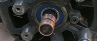
The next problem is wear on the slip rings of the generator rotor. Quite “adult” cars suffer from this disease. Remove the back cover from the generator and carefully inspect the rings.
If they are in bad condition, we replace them. You can see how to replace the slip ring block in the video below.
Replacing the Niva generator rotor slip ring block
The next malfunction is the failure of rectifier or additional diodes. In order to check them, you will have to disconnect all stator windings. They are connected to the diodes using screw lugs.
We unscrew, remove, and test each diode with a multimeter set to diode testing mode. In direct connection, the device should show several hundred Ohms, in reverse - an infinitely large resistance. If this is not the case, change the diodes. Since the semiconductors are pressed into metal plates in the form of a double horseshoe, which are radiators and conductors, you will have to change the entire group of diodes along with the “horseshoe”. Additional diodes can be changed one at a time using a soldering iron.
Expert opinion
Alexey Bartosh
Specialist in repair and maintenance of electrical equipment and industrial electronics.
Ask a Question
To check the diodes, it is enough to disconnect the windings; there is no need to unsolder additional diodes. They will not interfere with the continuity of the rectifier diodes and will themselves ring perfectly.
Well, the last malfunction is a break or breakdown of the stator or rotor windings. We remove the brushes, turn off the windings and check them with an ohmmeter for breaks and short circuits to the housing. In addition to a break and a short to the housing, an interturn short circuit is possible. Without special equipment, it is impossible to detect a short-circuited turn, so you will have to limit yourself to only estimating the resistance and the lack of connection with the generator housing.
In the video below you can see how the field winding is checked using an audio test.
Continuity of the generator excitation winding