The tachometer does not work on the VAZ 2115
Determining the rotation of the crankshaft on VAZ-2115 passenger cars with injection engines is assigned to a device called a tachometer.
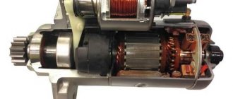
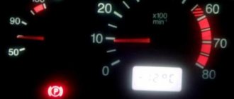
It is based on a stepper motor, on an armature shaft, which is mounted on a pointer. This is what will move along the tachometer scale, indicating the speed of the crankshaft when the engine is running. The angle of rotation of the arrow will depend on the signals received at the terminals of the stepper motor from the electronic control unit, and voltage pulses from the primary circuit of the ignition system. If the tachometer begins to “grumble” at the readings, then works normally, and then freezes in some position, then the driver first needs to perform a bar test (2115-3801010), which consists of checking the correct operation of all his devices. This test is very simple: simply press the reset button and, without releasing it, turn the ignition key to the ignition on position. If we see that the tachometer needle begins to move a little along the scale, and then returns and repeats this three times, the device is fully operational. In this case, the reasons for its failure should be looked for elsewhere.
Another possible result when running the test is that the tachometer needle refuses to move without the dial jerking, indicating a broken gauge. But before you start looking for a new dash, since tachometers are not sold separately, try checking the ground wire from pin 1 of the VDO X1 white strip. If the ground wire is OK, there is only one way out, replace the instrument cluster.
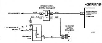
If your test shows that the tachometer is working properly, a driver who does not have knowledge of electrical engineering can only check the condition of the contacts for oxidation in the sockets through which signals from the ignition are received. The coil bank and electronic controller are supplied to VDO terminals 2 and 3 of X1. Tachometer terminal 2 is the low voltage input from the engine control unit, and terminal 3 is the high voltage input from the ignition coil assembly. The location of the ECU pins will depend on the brand of your ECU.
The most common breakdown
Before digging into the inside of the car, check how securely the ground wire leading to the front panel is secured. A restless passenger in front often simply pulls him out of his place with his feet. To prevent the situation from repeating itself, after fastening it is worth insulating the wire from reach.
Its signs are very characteristic:
- All indicators do not work: speedometer, tachometer, odometer, fuel level recorder, coolant temperature sensor;
- The rest of the equipment - optics, radio, even the panel backlight - turn on normally and do not act up;
- The ignition works properly, the car does not refuse to start;
- Fuse F3 is almost 100% blown. It is located in the mounting block and will have to be changed. But first you need to find out why it was covered, otherwise the new one installed will suffer the same fate. In most cases, a short circuit is to blame for burnout. On well-used VAZ-2115, the fuse often blows after each wash. Instead of carrying a spare one, you need to figure out where moisture is getting into it.
If the fuse is intact , this is not a reason to immediately leave it alone. It would be a good idea to remove it and check the contacts: if the fuse is live, but the terminals are oxidized, the circuit will be interrupted, and the device will stop showing any signs of life.
The next weak link : It is the ignition relay. It is located to the left of the steering column, fixed on a pin, so to speak, upside down. You need to remove it and try to make direct contact with the wires. If there are obvious signs of revival on the instrument panel, it immediately becomes clear that the time has come to change the relay.
Classification by operating principle
- Mechanical or electromechanical tachometer with direct drive. The revolutions are transmitted to the dial indicator through a flexible shaft, which receives the revolutions through a worm gear directly from the crankshaft or one of the transmission shafts. The indicator is based on the phenomenon of eddy current induction. The operation and design of a magnetic tachometer is very similar to the operation and design of a car speedometer. This tachometer design is not used in modern cars.
- Electric tachometer. A characteristic feature is the connection to an electric generator. Mainly used in diesel engines, but for uniformity, this type of device can also be used in gasoline engines.
- Electronic. The signal can be received both from the ignition system and directly from the computer. Installed in gasoline and diesel engines.
What is a tachometer and why is it needed?
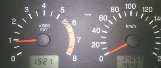
A tachometer is a device that, as I already said, shows the number of engine revolutions per minute (thousand rpm). The tachometer readings are necessary to make it easier for the driver (usually a beginner) to navigate and correctly select the desired gear (up or down). A tachometer is also necessary in order to monitor the correct operation of the engine by the number of revolutions. For example, when the speed fluctuates or is too high, a fault can be detected in time.
The first tachometers were analog (they are also called dial gauges). Analog tachometers have a dial with numbers and an arrow. One division of the analog tachometer is equal to 1 thousand revolutions. A little later, digital (electronic) tachometers began to appear on mostly Western-made cars. Data in electronic tachometers is displayed on a display (LCD or LCD display). In modern cars, digital tachometers look like analog ones because, like older tachometer models, they display information in the form of a dial and an arrow that indicates the number of revolutions.
Design and principle of operation
Main components of electric and electronic tachometers:
- Unit of measurement or signal converter. It can be based on analog circuit elements or built on special microcircuits;
- Display with analogue or digital speed indication;
- auxiliary elements.
Electronic tachometers work by converting individual signals or pulses received from the ECU, ignition system or alternator into a signal that the display unit can understand.
The electronic tachometer works by converting individual signals or pulses received from the engine control unit, ignition system or generator into a signal that can be read by the display.
Connection diagram
When looking for the reason why the tachometer does not work, you must first understand the connection diagram and signal type. There are 3 common connection schemes:
- to a contactless ignition system (the tachometer output is connected to the primary circuit of the ignition coil). The operating principle is based on measuring the frequency of voltage surges in the primary circuit of the ignition system. It is impossible to calculate the ignition angle without taking into account the number of crankshaft revolutions, so the sparking frequency directly depends on the crankshaft speed. In 4-cylinder internal combustion engines, one full revolution of the crankshaft corresponds to 2 voltage pulses in the primary circuit. Accordingly, the higher the crankshaft rotation speed, the greater the frequency of voltage surges;
- connection to the contact ignition system. The operating principle and connection diagram are similar to the BSZ, but the measuring device will differ depending on the voltages in the input circuit;
- connection to the engine ECU. The operating principle is still based on recording voltage pulses in the primary circuit of the ignition system, but the signal to the tachometer comes from the engine control unit;
- connection to the generator (the tachometer signal pin is connected to the W pin of the generator). The generator pulley is driven by a belt drive from the crankshaft, so the rotation speed of the generator rotor will always be proportional to the rotation speed of the crankshaft. The change in crankshaft rotation can be calculated by continuously measuring the amount of emf generated across the winding. The principle of operation of a tachometer is similar to a conventional voltmeter.
The role of the tachometer in driving a car
The VAZ 2109 tachometer is a device that displays the rotation speed of the engine crankshaft in thousands of revolutions per minute. Modern cars, including those produced by AvtoVAZ, are required to be equipped with a tachometer. This is reasonable, since the device provides the driver with information important for adequate control of the car.
First of all, engine speed must be taken into account when choosing a gear. The VAZ 2109 is equipped with a manual transmission, and the choice of a specific gear appropriate to the driving conditions is the responsibility of the driver. The design of the engine is such that it operates in the most economical mode at speeds in the range of 2 - 2.5 thousand rpm. It is precisely these tachometer readings that the driver must provide when driving uniformly along a horizontal section of the road with a hard surface. The choice of engine operating mode depending on driving conditions is determined by the driver’s qualifications, but the tachometer on the VAZ 2109 helps make the right choice. In addition, based on the readings of this device, the engine is adjusted and the idle speed is selected to ensure the stability and efficiency of the internal combustion engine.
If your car has a low panel and does not have a tachometer, you can install one. There are different, including budget models available on the market. You can choose a tachometer option for the VAZ 2109 with a liquid crystal numerical indicator. It will fit comfortably on the dashboard next to the ignition switch.
Connecting the VAZ 2109 tachometer is easy to do with your own hands - there are only three wires, including ground. The tachometer connection diagram is included in the installation kit.
October 2009
| Mon | W | Wed | Thu | Fri | Sat | Sun |
| « Sep | But I " | |||||
| 1 | 2 | 3 | 4 | |||
| 5 | 6 | 7 | 8 | 9 | 10 | 11 |
| 12 | 13 | 14 | 15 | 16 | 17 | 18 |
| 19 | 20 | 21 | 22 | 23 | 24 | 25 |
| 26 | 27 | 28 | 29 | 30 | 31 | |
Recently, quite a lot of friends and acquaintances have been changing their carb systems to an injector. In principle, there is quite a lot of information on this matter... But people periodically have some questions... In this article I will tell you how to connect a tachometer and speedometer to an injection car with an old-style instrument panel (not VDO!)
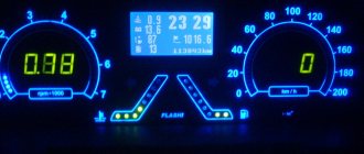
I myself solved this problem simply - I installed a VDO panel. Everything there is simple and clear, and I have enough information on connection on my blog. But as practice shows, sometimes people do not have the opportunity to buy VDO, since the budget is limited... And sometimes, out of ignorance, they prefer not to worry at all and drive without a speedometer and tachometer.
Speedometer As we know, on old-style devices there is no speed sensor, but a speedometer cable. The dashboard also does not have a speedometer signal input, but there is a hole for the speed cable. The problem is easily solved, you just need to buy a suitable speed sensor. According to their design, there are two types. One without cable implementation
install such a sensor on the VDO dash
But such a sensor is installed on the devices with a cable
Those. it is connected to the COURT harness, and the cable is also inserted into its hole. those. the sensor takes data without disturbing the old design.
That's basically all about the speed sensor. The only thing worth considering is that there are different connectors, be guided by the one you need.
Tachometer
They told me that on the instrument panel of a tall torpedo there is a separate input for a low-voltage tachometer - pin 5 of the red block.
The following can only be considered as a theory of converting a high-voltage signal into a low-voltage one
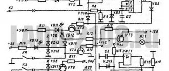
The situation with this issue is even more complicated than with the speed sensor. To be honest, many friends asked “how do we connect the tachometer?” ... I kept silent and said, “I know it’s possible, but how? xs." Again, as for the VDO panel, everything is simple, there are initially two connectors on the white block for connecting the tachometer injection signal (pin 2) and for connecting a high-voltage signal (pin 3). A high-voltage signal is needed when the VDO tidy is installed on a carburetor car. But what if the tidy is old? I thought about this a lot, especially because I have an old instrument panel and tachometer on one injection machine. I was too lazy to look at how everything was implemented... Out of boredom today I started studying electrical circuit diagrams and came to an interesting observation. ’ll just make a reservation right away: I haven’t tested this in practice, so I can’t vouch for it. If someone checks it, please write about your success. While studying the circuit diagram of the VDO instrument panel, I noticed that the only difference in each signal input is that there is a resistor on the high-voltage track. that's all. everything is very simple. I dare to suggest that on the old tidy there is also a resistor on the tachometer track that converts the high-voltage signal into a low-voltage one. Therefore, to connect an injection tachometer to this tidy, you just need to disassemble the tidy, pay attention to the contact path that comes from pin 3 of the red block and find this resistor. Remove the resistor from the device or bypass it. those. solder the bypass wire. Again, I emphasize that these are all just theoretical thoughts, since I myself have not disassembled the device. If anyone does it, be sure to post the results. If someone sends photos of the disassembled device or a report on this operation, I will be grateful.
I checked it with the tachometer. I just connected the device with VP to January 7.2. Everything is a bundle, there are no problems, you don’t need to do anything with the resistor, just stretch the wire from the instrument panel (red connector, 3rd pin, red-brown wire) to the controller wiring (it’s also red-brown there). Everything works great. Thanks for the tip, I thought there was a completely different signal there.)
- Mechanical or electromechanical tachometers with direct drive. The revolutions are transmitted to the dial indicator through a flexible shaft, which, through a worm gear, receives rotation directly from the crankshaft or one of the transmission shafts. The operating principle of the indicator is based on the phenomenon of eddy current induction. The operation and design of a magnetic tachometer are extremely similar to the operating principle of a car speedometer. In modern cars, a similar tachometer design is not used.
- Electric machine. A distinctive feature is the connection to a generator. It is used primarily on diesel engines, but for the purpose of unification, a device of this type can also be used on gasoline engines.
- Electronic. The signal can be taken either from the ignition system or directly from the computer. Installed on gasoline and diesel internal combustion engines.
Design and principle of operation
Main components of electric machine and electronic tachometers:
- measuring unit, or signal converter. It can be based on elements of analog circuitry or built using special microcircuits;
- display unit with analogue or digital display of the number of revolutions;
- auxiliary elements.
The operation of electronic tachometers is based on the conversion of individual signals or pulses captured from the computer, ignition system or generator into a signal “understandable” for the display unit.
Connection diagram
When looking for the reason why the tachometer does not work, it is first of all important to understand the connection diagram and the type of signal. There are 3 typical connection schemes:
- to a contactless ignition system (the tachometer wire is connected to the primary circuit of the ignition coil). The operating principle is based on measuring the frequency of voltage surges in the primary circuit of the ignition system. Calculating the ignition angle is impossible without focusing on the number of crankshaft revolutions, therefore the sparking frequency directly depends on the crankshaft rotation speed. On 4-cylinder internal combustion engines, a full revolution of the crankshaft corresponds to 2 voltage pulses in the primary circuit. Accordingly, the higher the crankshaft rotation speed, the greater the frequency of voltage surges;
- connection to the contact ignition system. The operating principle and connection diagram are similar to the BSZ, but the design of the measuring unit will differ depending on the voltage of the input circuit;
- connection to the engine ECU. The principle of operation is still based on recording voltage pulses in the primary circuit of the ignition system, but the signal to the tachometer comes from the engine control unit;
- connection to the generator (the tachometer signal contact is connected to terminal W of the generator). The rotation of the generator pulley is carried out by a belt drive from the crankshaft, so the rotation speed of the generator rotor will always be proportional to the crankshaft speed. The change in the number of revolutions of the crankshaft can be calculated by constantly measuring the amount of EMF generated on the winding. According to its principle of operation, an electric machine tachometer resembles a regular one class=”aligncenter” width=”448″ height=”412″[/img]
Typical faults
If the mechanical tachometer on a car stops working, there is mechanical damage to any of the structural elements. A broken cable of a flexible shaft, wear of the worm gear elements, the appearance of backlashes, deformations - all these reasons can cause the engine speed indicator to fail.
What to pay attention to if the electronic tachometer does not work:
- integrity of electrical wiring. In this case, it is important to check not only the signal wire, but also the ground and power supply of the instrument panel;
- quality of contacts. The presence of oxides and loose contact inside the chips may well cause the tachometer to fail;
- the integrity of the elements of the measuring unit, which are located behind the protective glass inside the dashboard. Among mechanical damage to transistors, burnout of microcircuits, tracks or swelling of resistors, the most common reason for a non-working tachometer is a violation of solder integrity. For example, on the Mitsubishi Padjero II, the appearance of microcracks in the soldering areas of the tachometer elements is a generally recognized disease.
On vehicles with an alternator connection, a non-functioning tachometer may indicate a faulty alternator. In this case, the breakdown is accompanied by the lighting of the low battery charge indicator and the sporadic lighting of a “garland” of warning lights on the dashboard.
In some types of design, changes in the linear resistance of high-voltage wires can make adjustments to the accuracy of the engine speed indication.
How to find the cause of the problem yourself
In addition to a visual inspection, for DIY diagnostics you will need a universal measuring device. If you know how to use a multimeter, you can easily check the power supply, ground, and also test the signal wire for a break.
The power supply is checked in DC measurement mode, the measurement range is up to 20 V. “Minus” is constant, “plus” appears only after the ignition is turned on. Pulses on the signal wire should appear when the crankshaft rotates. To search for a break, the multimeter must be switched to resistance measurement mode - ohmmeter. Sometimes, to detect a bad contact, it is enough to move the connector or harness in which the signal wire of the speed indicator is laid.
Tachometer needle twitches
The problem of a twitching needle is best known to owners of the GAZ 3110 Volga.
The problem occurs on cars manufactured before September 1999 and equipped with instrument cluster 38.3801 (JSC Avtopribor). Due to design defects, the natural operation of a car generator, in which the amount of charging current is regulated by an alternating voltage supply to the excitation winding, leads to the twitching of the needle. The tachometer needle may twitch due to weakened tension of the alternator belt, but in most cases it is possible to repair the tachometer on the Volga by replacing the dashboard and modifying the connection diagram.
Typical faults
If your car's mechanical tachometer stops working, there is a mechanical problem. Breakage of the flexible shaft cable, wear of the worm gear parts, the appearance of backlash, deformation - all these reasons can lead to the engine speed indicator stopping working.
What to pay attention to if the electronic tachometer does not work:
- Integrity of electrical wiring. In this case, check not only the signal cable, but also the ground, that is, the power supply to the instrument panel;
- quality of contacts. The presence of oxides and loose contact inside the microcircuits can cause the tachometer to fail;
- The continuity of the elements of the measuring unit, which are located behind the protective glass inside the instrument panel. Among mechanical failures of transistors, burned-out microcircuits, traces or burnt resistors, the most common cause of tachometer failure is a violation of solder integrity. For example, in the Mitsubishi Padjero II, the appearance of microcracks in the soldered elements of the tachometer is a constant problem.
On cars with a generator connection circuit, a non-functioning tachometer may be a sign of generator failure. In this case, the failure is accompanied by the inclusion of a low battery indicator and the periodic switching on of a “garland” of warning lights on the instrument panel.
In some types of design, changes in the resistance of the high voltage cables may cause the accuracy of the engine speed reading to be adjusted.
Private situations
General signs do not always indicate specific breakdowns.
There may be exceptions. If individual devices refuse to work, it is quite possible that this is their personal problem. You'll have to parse the specific pointer. It may have a cracked gear that needs to be replaced.
- If the fuel gauge and tachometer are capricious (either they function, or they don’t react at all), the contacts and the mounting block are normal - you need to do a small check.
- Reset is pressed and held, and the ignition is turned on at the same time. Raised arrows indicate the need for further searches. Lifeless - that microcracks have appeared in the shield itself. You will have to remove it and examine all soldering and traces under a magnifying glass. In principle, these are all the main options. If calling all the listed components and parts did not lead to the revival of the instrument panel, your case is individual, and you will have to determine the situation in the company of an experienced auto mechanic.
- Check the 15A fuse to see if there is a short circuit on it or if it burns out immediately after you insert it. I had exactly the same thing; 3 fuses were replaced and burned out immediately. It’s better to go to a competent electrician, or better yet several, and listen to what they say. One master did everything for me for 1000.
- Sometimes the speedometer and tachometer will fail. The fuel level will begin to show left readings - i.e. not on the scale, but somewhere behind the scale. A panel test helps. Hold down the mileage reset button, then turn on the ignition. The test mode will start, if it doesn’t work, then you’ll have to dig further.
- Look for the lost minus. If it does not light up after ignition, it should light up from the backlight. if it is not there, then dig minus. Look at the body from the battery at the same time. there may be trouble there too.
- There was such a thing - it turned out that the ignition relay was bad, several times everything went out at full speed in the third row, along with the turn signals and dimensions, at the same time the wipers were switched off, and even in the snow. The method of deduction did not help, the advice of experienced people almost led me into the wilds, it turned out that there was a crappy contact in the relay block, I disassembled the block, took out the terminals, tightened it a little, the main thing here is not to overdo it, otherwise you won’t push the relay, I assembled everything, at the same time I switched the relay to 40A - earned!
How to find the cause of the problem yourself
In addition to a visual inspection, you will need a universal measuring device for your own diagnostics. If you know how to use a multimeter, you can easily check the power, ground, and also check the signal wire for a break.
The power test is performed in DC measurement mode, and the measurement range is up to 20 V. “Minus” is constant, “plus” appears only after the ignition is turned on. Pulses on the signal line should appear when the crankshaft rotates. To find damage, you need to switch the multimeter to resistance measurement mode - ohmmeter. Sometimes, to detect a bad contact, it is enough to shake the connector or harness in which the wire is laid. Signal speed indicator.
Tachometer needle twitches
Owners of Gas 3110 Volgas are most familiar with the problem of vibration arrows. The problem occurs in cars manufactured before September 1999 and equipped with a set of indicators 38.3801 (JSC AVTOPRIBOR). Due to construction defects, the car generator for natural operation when charging, the current is regulated by alternating voltage, supplied winding excitation, towing the arrow.
The tachometer needle may vibrate due to loose alternator belt tension, but in most cases it is possible to repair the tachometer in Bełdze by replacing the instrument panel and modifying the wiring diagram.