Greetings, dear friends, to our website! In today’s article I would like to tell you about such an important part of the car as the starter relay, or, more precisely, about its malfunctions and how to repair it yourself. We will look at the example of a popular domestic car - the Chevrolet Niva.
When the engine is started, during the ignition operation, power is supplied to all the windings that are located in the starter. These windings come in two types: retracting and holding. The starter is connected to the retractor winding, and the entire housing control circuit begins to work thanks to the holding winding. When current flows to the terminals, magnetic induction occurs, which creates a magnetic field. Thus, the armature presses on the return spring, and the bendix rotates. When the engine starts running, the power is turned off and the armature returns to its original position as the spring returns it. The contacts are disconnected.
A relay is a device that is constantly powered by electric current from a battery. It consists of a gear with teeth that engages the flywheel ring when the relay begins to operate. As a result, the engine crankshaft rotates and the car starts. During operation, the relay connects the flywheel and bendix gears. The starter will run empty if the relay does not advance the gear.
If the starter relay works well, then the power is at 8 V and the temperature does not exceed 25 ° C. In the case when the power is above this mark, then you need to look for faults in the starter and its relay.
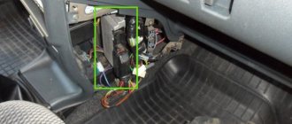
Where is the starter relay located on a Chevrolet Niva
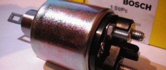
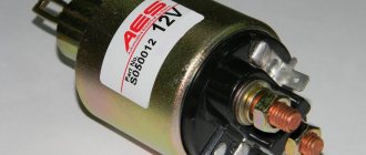
On the Shnivy, the relay is located on the right fender of the car between the battery and the starter. The device can be easily recognized by its appearance - it is a black block of a standard size with leads for 4 contacts and a grounding strip.
The fifth pin is used for mounting the part on a metal part of the car. It should be taken into account that the location of the relay is relevant not only for cars manufactured in 2005. The device is found here and in cars manufactured in:
- 2003;
- 2004;
- 2006;
- 2007;
- 2008.
Since 2009
On the car model after restyling, the location of the fuse has changed slightly. In versions like:
- 2010;
- 2011;
- 2012;
- 2013;
- 2014;
- 2015.
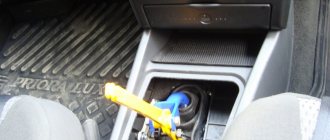
The relay was moved to a mounting block under the dashboard. To access the unit, you will need to remove the protective casing and part of the console.
Cars assembled before 2009
Main unit
Mounting block 2110-3722010-08 (option 1)
Mounting block 2110-3722010-01 (option 2)
Circuit breakers
| Designation | Denomination, A | Purpose |
| F1 | 5 | Lighting for trunk, engine compartment, license plate; Instrument panel lighting; Front side lights |
| F2 | 7.5 | Low beam (left headlight); Corrector motor gearbox (left headlight); Electric corrector |
| F3 | 10 | Left high beam |
| F4 | 10 | Left PTF |
| F5 | 30 | Electric windows |
| F6 | 15 | Electric door lock |
| F7 | 20 | Cigarette lighter; Sound signal |
| F8 | 20 | Heated rear window |
| F9 | 20 | Glove compartment lighting; Windshield wiper and switch; Electric motors for headlight cleaners and headlight washers |
| F10 | – | Reserve (not used) |
| F11 | 5 | Tail lights; Instrument panel light control |
| F12 | 7.5 | Low beam (right headlight); Corrector motor gearbox (right headlight) |
| F13 | 10 | High beam (right headlight) |
| F14 | 10 | Right PTF |
| F15 | 20 | Exterior mirror control unit; Exterior mirror control motors |
| F16 | 10 | Turn signals and hazard warning lights (in hazard mode) |
| F17 | 7.5 | Lamp lamps for individual lighting and interior lighting; Immobilizer warning lamp; Brake lights |
| F18 | 25 | Reversing lights; Electric heater fan; Windshield washer motor; Rear window heating, wiper and washer; Door lock |
| F19 | 10 | Direction and hazard indicators (in turn signal mode); Devices; Differential lock indicator lamp |
| F20 | 7.5 | Rear fog lights |
Relay
| Designation | Purpose |
| K1 | Lamp health monitoring |
| K2 | Windshield wiper |
| K3 | Turn signal and hazard warning light switch |
| K4 | dipped headlights |
| K5 | High beam headlights |
| K6 | Additional |
| K7 | Heated rear window |
| K8 | Reserve |
Additional relay block
| Designation | Purpose |
| 1 | Electric windows |
| 2 | Fog lights |
| 3 | Horn or heated seats |
| 4 | Electric exterior mirrors |
Fuel injection system mounting block
Circuit breakers
| Designation | Denomination, A | Purpose |
| 2 | 50 | Right electric cooling fan |
| 3 | 15 | Gasoline pump |
| 4 | 15 | Controller |
| 9 | 50 | Left electric cooling fan |
| 10 | 15 | Power circuits switched on by the main relay |
Relay
| Designation | Purpose |
| 1 | Additional (turns on the right electric fan through a resistor at low rotation speed) |
| 5 | Right electric fan |
| 6 | Left electric fan |
| 7 | Gasoline pump |
| 8 | Main relay |
Principle of operation
The blocking device is responsible for turning on the device strictly at a certain moment. After turning on the ignition, a signal is sent to the starter and the bendix is activated, the armature of the electric motor engages with the flywheel and begins to rotate. An additional relay involves cutting off power to the motor after it has been successfully started.
The starter turns off after the engine starts running, which would be impossible if there was no blocking. The protective insert also prevents overloads and fires in the car.
Cars assembled after 2009
Main mounting block
Mounting block 2123-3722010
Circuit breakers
| Designation | Denomination, A | Purpose |
| F1 | 5 | License plate lamps; Indicator lamp for external lighting in combination, turning on side lights in the external lighting switch; Engine compartment light; PTF; Additional brake light; Side lights (left side) |
| F2 | 7.5 | Low beam (left side) |
| F3 | 10 | High beam (right side); High beam warning lamp in the instrument cluster |
| F4 | 10 | Left PTF |
| F5 | 30 | Power windows for front doors |
| F6 | 15 | Cigarette lighter |
| F7 | 20 | Sound signal; Trunk light |
| F8 | 25 | Heated rear window and exterior mirrors |
| F9 | 20 | Heated rear window; Windshield and rear window cleaner; Headlight cleaner and washer; Switch for windshield and rear window wipers and washers, rear window washer motor; Headlight washer motor; Glove box light |
| F10 | 20 | Door lock ECU (electrical package ECU on vehicles with trim levels No. 55, 34) |
| F11 | 5 | Side lights (starboard side); Instrument lighting control (potentiometer) |
| F12 | 7.5 | Right headlight (low beam); Corrector motor gearboxes |
| F13 | 10 | Right headlight (high beam) |
| F14 | 10 | Right PTF. |
| F15 | 20 | Heated front seats; ECU for electric heating, ECU for electric mirrors, Electric exterior mirrors |
| F16 | 10 | Direction indicators and hazard warning lights (in hazard warning mode); Turn signal lamps |
| F17 | 7.5 | Interior lighting, individual lighting; Brake lamps; Immobilizer warning light |
| F18 | 25 | Heater motor switch; Heater motor |
| F19 | 10 | Brake fluid level sensor and brake fluid level indicator in the instrument cluster; Direction and hazard indicators (in turn signal mode); Turn signal lamps; Turn signal indicator lamps in the instrument cluster; Heated front seats; Starter; Instrument cluster; Air conditioner switch |
| F20 | 7.5 | Immobilizer; Rear fog lights |
Relay
| Designation | Purpose |
| K1 | Monitoring the serviceability of lamps (replaced by jumpers) |
| K2 | Windshield wiper |
| K3 | Direction indicators and hazard warning lights |
| K4 | dipped headlights |
| K5 | High beam headlights |
| K6 | Heated trunk door glass; Heater fan; Windshield and rear window cleaner and washer |
| K7 | Heated rear window |
| K8 | Not used |
Additional relays
| Designation | Purpose |
| 2 | Window lifters |
| 3 | Seat heating |
| 4 | Sound signal |
| 5 | Starter |
Injection system mounting block
Circuit breakers
| Designation | Denomination, A | Purpose |
| 2 | 50 | Right electric cooling fan |
| 3 | 15 | Gasoline pump |
| 4 | 15 | Controller |
| 9 | 50 | Left electric cooling fan |
| 10 | 15 | Power circuits switched on by the main relay |
Relay
| Designation | Purpose |
| 1 | Additional (turns on the right electric fan through a resistor at low rotation speed) |
| 5 | Right electric fan |
| 6 | Left electric fan |
| 7 | Gasoline pump |
| 8 | Main relay |
Air conditioner unit
It contains:
- air conditioning compressor relay,
- fuse rated 10 A.
Repair manuals
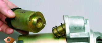
Due to the design features, the relay on most cars is a block module that cannot be repaired. It’s the same here – they cannot be disassembled and are in a sealed case.
The usual repair procedure involves diagnosing the entire circuit of the device and replacing the relay with a known good one.
Shniva won't start, starter relay clicks
If the starter does not turn, but the relay clicks, the problem should be looked for after it. The technicians first check the bendix and the solenoid relay. These components are also not subject to repair; if a breakdown is detected, they should be replaced.
Checking the mechanism: step-by-step instructions
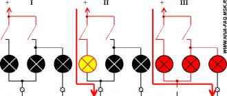
To understand what the fuse means and whether the relay is functioning, it is recommended to pay attention to the following signals:
- a whirring sound coming from under the hood with the engine running but not turning over;
- starter operation without a running engine;
- Starter clicking sounds (won't start).
If such signs are present, the relay should be replaced. Before this, a check is carried out. The device is removed. The contacts on the back wall are closed. To close the circuit, you need to attach a piece of metal or wire. If after this the starter starts working without failures, then the main problem lies in the relay of this element. When the starter starts to operate and the relay starts, then it is the starter that will need to be repaired or replaced.
Replacing the starter relay Shnivy
To remove the retractor toggle, you will need to perform an operation.
- Place the machine on a level surface and securely fix it.
- Disconnect the power terminals from the battery.
- Using a screwdriver or a No. 8 wrench, unscrew the starter power wires.
- Under the car, you will need to unscrew the nuts of the starter mounting studs from the engine housing.
- Next, the starter is removed from its seat and dismantled from the car.
- The spring clamps of the retracting element are dismantled.
- Installing the new part and reassembling is done in reverse order.
Power sensor
If various elements in the car do not work, then first of all we begin to look for the fuse that is responsible for this device. This can be easily done if you rely on the information provided above, and take it out of its seat; this can be done with tweezers.
After removal, we carry out a visual inspection of the appearance; if there are no external defects, then we resort to using a tester, switch it to the prozvana mode, and the probes should be placed on the ends of the fuse. If the element is faulty there will be silence, if it is normal, the tester will start making sounds. Once a faulty fuse is found, it should be replaced with a new one designed for the required current value. As you can see, the procedure for detecting and replacing burnt-out elements is not a complicated procedure, and you can do it yourself.
There are two types of car blocks - for those produced before and after 2009. Unfortunately, parts from cars before and after restyling are not interchangeable. But the blocks located behind the glove box have virtually no structural differences. that is why when replacing them, the year of manufacture of the car will not matter.
The protective device may fail due to long periods of use, so if any consumer stops working, the first thing to check is its fuse.
They are held in their nests by sliding contacts. In order to remove the element, simply pull it out of the socket. To make this more convenient, modern mounting blocks are equipped with plastic tweezers.
A faulty fuse can be determined by visual inspection or using an ohmmeter. Since the housings are made of transparent plastic, the integrity of the conductor is easy to determine with the naked eye. In addition, conductor burnout is accompanied by an increase in temperature. Traces of heat exposure remain on the plastic case. Having selected an element suitable for its nominal value, it is inserted into the socket in place of the failed one.
If a fuse burns out on the road, you can replace it with an identical one that protects the circuit of the consumer that is not currently in use.
More information about Chevrolet Niva electronics can be found here.
The ignition relay is located in the passenger compartment fuse box; it can be found on the driver's side of the instrument panel, opposite the seat. On the diagram it is usually designated K6 and in the technical description it is sometimes called an addition relay.
It is responsible for turning on the fuel pump and supplying voltage to other elements. Triggered when the ignition key is turned. At this moment, you can hear a click behind the instrument panel. This electric coil built into the relay receives voltage and closes the contacts of a certain circuit. If there is no characteristic sound when turning the key, this may indicate its failure.
This element is marked K3 in the diagram. It is responsible not only for the turn lamps, but is also activated when the hazard lights are turned on. It has a slightly different structure, unlike K4 and K5, since it has a built-in timer that turns on and off the circuit at a given interval. Thanks to this, it ensures that the lamps flicker.
But if everything is in order with the relay, and the devices do not work, then there may be a problem elsewhere - the mass attachment point. The negative wire coming out of the battery is connected to the car body and goes to some of the main energy consumers in the form of wires. This is sometimes the difficulty when calling an electrician.
The architecture of the circuit can be described as follows: a wiring harness comes out of the negative terminal, connecting devices operating from one ground point, then wires connecting other ground points are connected to them using a crimp sleeve. As a result, finding a specific mass attachment point is quite difficult.
For example, the mass of the mirror control unit is located behind the trunk trim. But with the engine everything is a little simpler. Since it is connected to the frame and body through pads, which are essentially a dielectric, it has its own wiring harness. The terminals are located on the left side of the engine, below the ignition module. They are responsible for the operation of the ECU and ECM sensors.
If, after checking all of the above, you find the reason why the radiator fan does not turn on, you only have to check one wire - the radiator sensor wire. To do this, you must remove the switch as it does not allow access to the fuse box plugs. This means we remove the plug from the fuse block and check the radiator sensor wire for a break.
We check as follows: connect the wire to the “ ” terminal of the battery, install the second end into the connector of the chip. Next, remove the plug from the sensor and connect the light bulb. If there is no light bulb, make a “teal” to ground. If there is no voltage, most likely this wire is broken.
If the fan does not turn on, the reason may be completely unexpected, for example, a burnt gasket under the head. Switching on does not occur for the reason that the coolant does not enter the cylinder, while gases from the cylinder penetrate into the coolant, creating an effect known as an air lock.
WHAT TO DO IF THE RADIATOR COOLING FAN DOES NOT WORK
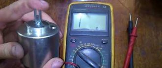
Problems with the electric motor. If the electric motor fails, its rotor will not spin, and accordingly, the impeller will not rotate. You can check the performance of the electric motor by connecting it directly to the battery. To do this, you will need to take two wires, connect them to two battery terminals and two electric motor terminals.
If the fan does not spin when connected directly to the battery, we can conclude that the electric motor needs to be replaced; Problems with the sensor. If the sensor is unable to detect the coolant temperature and transmit a signal to turn on the electric motor, it will need to be replaced. To make sure that it is not working, you need to disconnect two wires from it and short them together.
If the electric motor starts to spin the impeller, this will indicate that the sensor is faulty and needs to be replaced; There is no tension. The third and most common reason for a non-working radiator cooling fan is the lack of voltage in its power supply circuit. If there is a break in the wires or a fuse fails, the circuit will be de-energized.
RADIATOR COOLING FAN IS NOT WORKING: HOW TO USE THE CAR
Also interesting: Brake pads for VAZ 21214: selection and replacement
Try turning on forced operation of the fan from the battery; If the fan is not forced, you should drive at a constant speed of about 60 kilometers per hour or higher so that the oncoming air flow cools the fluid on the radiator without the help of a fan. It is also recommended to turn on the heating system in the car interior so that some of the heat from the coolant escapes into the cabin.
Technical parameters of Chevrolet Niva (2123) 1.7 / Chevrolet Niva (2123) in a 5-door body. SUV with an 80 hp engine, 5 manual transmission, produced from 2002 to 2009.
The designers of the Chevrolet Niva used a dual fan unit in the cooling system. This slightly complicated the connection diagram, but sharply increased the efficiency of radiator airflow. The fans are driven by 12-volt DC synchronous motors with a permanent magnet inductor. Electric motors have a closed, non-demountable design and do not require maintenance.
The power of each electric motor is 110 W. The fan assembly draws 18 amps.
The fans are turned on one by one using an electromagnetic relay controlled by the on-board computer. When the coolant heats up above 99 degrees, the electric fan located closer to the engine air intake starts. The switch-on temperature of the second impeller is 101 degrees. The fan connection diagram is shown below.
- Voltage is applied to the control terminals.
- Current passes through the inductor, resulting in an electromagnetic field.
- The steel contacts attract and close.
- The current passing through the relay drives the electric motor.
- Disconnect all wires
- Removing the upper pipe
- Removing the bumper
- If there is an air conditioner, bend the tubes (this must be done carefully, as they may burst) or drain the freon (filling it back will not be cheap), then remove the air conditioner radiator.
- You need to loosen the nuts on the radiator casing
- Tilt the radiator so that you can remove the fan unit
- Unscrew the bolts that secure the block and remove it
Paid links
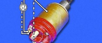
In this case, several stages of starting the engine occur when the key is turned: The retractor relay consists of a housing in which two windings, a magnet, an armature and a spring are located.
When power is supplied under the influence of an electromagnetic field, the armature compresses the spring, causing the bendix to rotate.
After the engine starts, the power is turned off and the spring returns the armature. The main types of malfunctions of the Chevrolet Niva relay are damage to the contacts, burnout, wear of the spring or armature, destruction of the housing or parts.
It is important to remember that the device is made in the form of a solid body, so its repair is not always possible or advisable. Therefore, it is better to replace the relay completely.
How to change fuses?
To change the fuse links in the Niva Chevrolet fuse box, you need to understand the electrical circuit of the car. A failed fuse can be identified visually or using a tester. To do this, turn on the device in the closed circuit sound test mode and install the probe tips on the fuse contacts.
Test procedure and tweezers
The replacement itself, for example, a windshield wiper fuse with a rating of 20 A (position F9 on both blocks), is carried out as follows:
- Open the block cover.
- Find the failed insert.
- Take it with tweezers and pull it out of the nest.
- A fuse of the same rating must be installed instead. The use of inserts of a higher rating can lead to burnout of the unit and electrical wiring, as well as to a vehicle fire. Using parts with a lower rating will also not protect the circuit, since such an insert will immediately burn out.
- Turn on the circuit in which the insert was replaced. If re-burnout occurs, then the problem is in the elements of this circuit.
- Place the tweezers in their original place and close the lid.
The process of replacing one of the fuses is shown in the video from the Remgar channel.