Tips for motorists
Quite often, in domestic cars equipped with ECUs, there are malfunctions in the operation of the dashboard instruments. These include the tachometer.
Many drivers, especially beginners, ask the question why the tachometer on the VAZ 2114 does not work ? There may be several reasons for this.
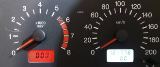
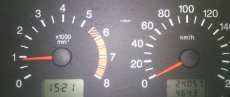
First, let's check the serviceability of the indicator itself; to do this, we carry out diagnostics on the instrument panel by clicking on the odometer reset, with the ignition off, turn on the ignition, as a result of which all the instrument panel arrows should rise to the maximum level and return back. If the tachometer needle does not respond during diagnostics, the pointer is most likely faulty; the remedy is to replace the instrument panel. It’s even easier to check the indicator, if the car has an on-board computer and it shows the revolutions, it means the problem is in the indicator.
Sometimes a malfunction occurs, expressed in jumps in the tachometer needle, or periodic shutdowns (works, does not work), most likely the fault here is poor contact in the wire blocks that supply and control the tachometer, or weak ground contact, on the tachometer or on ECU. It is also possible that the control circuit from the computer to the tachometer may be broken. The solution is to check the quality of the contacts on all tachometer wires. Also, the tachometer may not work together with all the other devices; the reason here is most likely in the supply of power to the panel, or rather its absence or not constant contact. The elimination method is to eliminate the cause of the lack of power - a blown fuse or an open circuit.
So, why does the tachometer on the VAZ 2114 not work? It does not work because either the device itself is faulty, or the circuits that supply and control it have a break or unauthorized contact, i.e. short circuit.
The tachometer in a car is used to indicate the number of revolutions of the engine crankshaft. Let's look at why the tachometer doesn't work and how to find and eliminate the cause of the breakdown. We will definitely dwell on the device and principle of operation, which will help to find out why the tachometer stopped working, the needle twitches or behaves inappropriately.
If the tachometer on a VAZ does not work
Usually, the lack of response from the arrow is due to a broken contact in the connectors of the main wires of its connection, or damage to the wiring of the circuit. The first step is:
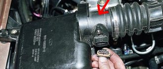
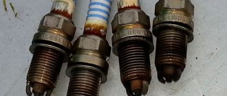
- Inspect the fastening of the conductor in brown insulation to terminal “K” on the ignition coil. If you detect poor contact, traces of oxidation, burning of a wire or terminal, fix the problem by cleaning the problem areas, treating them with anti-corrosion liquid, and tightening the fastening nut.
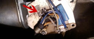
- Check the reliability of the connection of the black and white wire to the vehicle ground. If contact is broken, clean the wire and the surface to which it is attached.
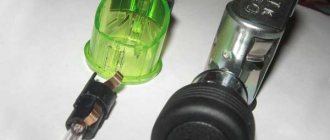
- Using a tester, determine whether voltage is supplied to the red wire when the ignition is on. If there is no voltage, check the serviceability of fuse F-9, which is responsible for the integrity of the instrument panel circuit, as well as the condition of the ignition switch contacts.
- Disassemble the instrument panel and check the connections of the contacts in the tachometer wiring harness block. “Ring” all the wires going to the device with a tester.
Classification by operating principle
- Mechanical or electromechanical tachometers with direct drive. The revolutions are transmitted to the dial indicator through a flexible shaft, which, through a worm gear, receives rotation directly from the crankshaft or one of the transmission shafts. The operating principle of the indicator is based on the phenomenon of eddy current induction. The operation and design of a magnetic tachometer are extremely similar to the operating principle of a car speedometer. In modern cars, a similar tachometer design is not used.
- Electric machine. A distinctive feature is the connection to a generator. It is used primarily on diesel engines, but for the purpose of unification, a device of this type can also be used on gasoline engines.
- Electronic. The signal can be taken either from the ignition system or directly from the computer. Installed on gasoline and diesel internal combustion engines.
Design and principle of operation
Main components of electric machine and electronic tachometers:
- measuring unit, or signal converter. It can be based on elements of analog circuitry or built using special microcircuits;
- display unit with analogue or digital display of the number of revolutions;
- auxiliary elements.
The operation of electronic tachometers is based on the conversion of individual signals or pulses captured from the computer, ignition system or generator into a signal “understandable” for the display unit.
Connection diagram
When looking for the reason why the tachometer does not work, it is first of all important to understand the connection diagram and the type of signal. There are 3 typical connection schemes:
- to a contactless ignition system (the tachometer wire is connected to the primary circuit of the ignition coil). The operating principle is based on measuring the frequency of voltage surges in the primary circuit of the ignition system. Calculating the ignition angle is impossible without focusing on the number of crankshaft revolutions, therefore the sparking frequency directly depends on the crankshaft rotation speed. On 4-cylinder internal combustion engines, a full revolution of the crankshaft corresponds to 2 voltage pulses in the primary circuit. Accordingly, the higher the crankshaft rotation speed, the greater the frequency of voltage surges;
- connection to the contact ignition system. The operating principle and connection diagram are similar to the BSZ, but the design of the measuring unit will differ depending on the voltage of the input circuit;
- connection to the engine ECU. The principle of operation is still based on recording voltage pulses in the primary circuit of the ignition system, but the signal to the tachometer comes from the engine control unit;
- connection to the generator (the tachometer signal contact is connected to terminal W of the generator). The rotation of the generator pulley is carried out by a belt drive from the crankshaft, so the rotation speed of the generator rotor will always be proportional to the crankshaft speed. The change in the number of revolutions of the crankshaft can be calculated by constantly measuring the amount of EMF generated on the winding. According to its principle of operation, an electric machine tachometer resembles a regular one class=”aligncenter” width=”448″ height=”412″[/img]
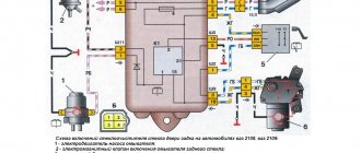
Connection diagram for tachometer VAZ-2108 and 2109
Let us immediately note that the fuel supply system – injector or carburetor – does not play a special role here. As you know, currently the most common are cars with the following engine types: gasoline or diesel. Depending on this, the tachometer is selected, unless, of course, it comes in the stock version. The thing is that on gasoline engines the tachometer reads data from the ignition coil, or rather, the impulses that arise here. However, the design of diesel power plants does not provide for this unit. Accordingly, here the tachometer reads pulses not from the ignition coil (for lack of one), but from the generator.
The first two wires (12-volt and Signal) are to contacts “B” and “K” of the ignition coil, respectively. All that remains is to secure the mass in any convenient place.
General information about VAZ-2114 sensors
Sensors look like small mechanisms. However, their role in the operation of the entire vehicle system is simply colossal. They signal the remaining fuel in the gas tank, inform the driver of the coolant temperature, and determine the position of various engine elements in a certain operating mode. In order to know your car well and understand what could fail in a given situation, you need to know the entire list of mechanisms involved in the system.
We list all the sensors on the VAZ-2114 injector 8 valves, which are the most important:
- Crankshaft positions.
- TPDZ.
- Camshaft position sensor.
- DTOZH.
- Speed.
- Idle move.
- DMRV.
- Lambda probe.
These devices are in most cases located in the engine compartment. Almost all of them are installed at the factory during vehicle assembly. But the driver himself can install some sensors at any suitable time. It is also important to know how each of these devices works and what primary task it performs.
Removing the car dashboard
- Using a Phillips screwdriver, remove the three screws that secure the center console;
- remove the cover, the protrusion located at the bottom, remove the protrusion from the bracket;
- Using a nozzle, unscrew the five screws located in the console on the right and remove the screen;
- Disconnect the terminal with the (-) sign from the battery. If there is a radio receiver, you need to remove it, remove the plug from the shield;
- Disconnect the wires coming from the cigarette lighter, remove the cartridge;
- Using a narrow screwdriver, remove the handle from the levers;
- pull the handle towards the heating and fan switch;
- unscrew the two screws above the panel and the two located under it using a screwdriver;
- unscrew the screw located behind the panel;
- Also unscrew the two self-tapping screws securing the cover;
- disconnect the harness and wire connectors. To avoid confusion when installing the panels, you should mark the order in which they are connected;
- unscrew the fastening bolts;
- unscrew the two self-tapping screws, those that secure the bottom bracket using an 8 key;
- unscrew the self-tapping screw securing the light guide and remove it;
- Also unscrew the screws securing the heating unit;
- remove lamp sockets;
- after removing the external parts, remove the decorative insert;
- unscrew all nuts with a 21 key;
- hydrocorrector, remove its lamp;
- Unscrew the screws that are attached to the cross member on the left.
- Finally, the panel itself is removed. The panel is assembled accordingly in the reverse order.
In general, the repair work is quite doable even with your own hands, but before starting dismantling work, you need at least a pinout mapped on paper, otherwise it will be difficult: you will need to “trace” every wire and every connection that is on the “path” from devices to the power button.
Crankshaft position sensor
You can often hear drivers with many years of experience calling this mechanism nothing other than a synchronization sensor. This name comes from the principle of operation of the device. The tasks of the DPKV are to synchronize the operation of the electronic unit and the gas distribution mechanism.
The VAZ-2114 is equipped with an inductive type DPKV. The cost of such a sensor is relatively small. If a vital controller for a car fails, most drivers prefer to immediately replace the device with a new one.
If the DPKV breaks down, further operation of the vehicle will become impossible. Without this mechanism, the fuel supply system will stop working, because the ECU will not receive information about when it is necessary to give a command to inject fuel into the cylinders. The location of the DPKV is in close proximity to the camshaft.
Electronics are responsible for fuel delivery in the VAZ-2114 car system. Without TPS, the control unit will not be able to determine the optimal time to supply gasoline. Deviations from the correct operation of the TPS lead to an increase in the amount of fuel consumed. The operation of many other car systems depends on the angle at which the remote control is located: cooling, fuel supply.
see also
The TPS is located near the idle speed sensor. In the “fourteenth” system, the work of these two devices is closely linked.
When the TPS breaks down, the car begins to twitch in a certain position of the damper, and instability of engine operation is also noted. All VAZ-2114 8 valve sensors are interconnected in their operation, so two different devices sometimes exhibit the same symptoms of malfunction. If symptoms of a breakdown occur, it is necessary to take a comprehensive approach to checking all controllers.
Pinout of the dashboard VAZ2108, 2109, 21099
Connection diagram of the instrument cluster before 1996.
1 — relay-interrupter for the parking brake warning lamp; 2 — tachometer with voltage stabilizer; 3 — instrument cluster lighting lamp; 4 — temperature indicator; 5 — BSK control unit; 6 — fuel level indicator; 7 - resistor 50 Ohm, 5 W; 8 — “CHECK ENGINE” control lamp for the toxicity reduction system; 9 — control lamp for high beam headlights; 10 — side light indicator lamp; 11 — backup warning lamp; 12 - warning lamp for unfastened seat belts; 13 — control lamp for left direction indicators; 14 - resistor 470 Ohm, 0.25 W; 15 - electronic voltmeter; 16 — control lamp for right direction indicators; 17 — warning lamp for emergency oil pressure; 18 — fuel reserve warning lamp; 19 — control lamp for the carburetor air damper; 20 — “CHECK ENGINE” warning lamp for the fuel injection system; 21 - parking brake warning lamp.
Instrument cluster wiring diagram after 1996
1 — tachometer; 2 — instrument cluster lighting lamp; 3 — temperature indicator; 4 — BSK control unit; 5 — fuel level indicator; 6 — “CHECK ENGINE” warning lamp for the toxicity reduction system; 7 — control lamp for high beam headlights; 8 — side light indicator lamp; 9 — backup warning lamp; 10 - warning lamp for unfastened seat belts; 11 — control lamp for left direction indicators; 12 — battery charge indicator lamp; 13 — control lamp for right direction indicators; 14 — warning lamp for emergency oil pressure; 15 — fuel reserve warning lamp; 16 — control lamp for the carburetor air damper; 17 — “CHECK ENGINE” warning lamp for the fuel injection system; 18 — parking brake warning lamp; B1 - 91 kOhm resistor; B2 - resistor 50 Ohm, 5 W.
Camshaft position sensor
This mechanism is located near the cylinder block. The main task is to transmit data to the ECU regarding the current operating cycle. Among specialists, the mechanism is called a Hall sensor. The operation of the device is based on the following principle: in accordance with the location of the crankshaft, the position of the gas distribution mechanism is determined. The data received by the sensor is reported to the electronic unit. Fuel is injected and the mixture is subsequently ignited.
Pinout of the dashboard of VAZ2110, 2111, 2112
- fuel reserve warning lamp;
- dashboard lighting lamps;
- right repeater indicator lamp;
- left repeater indicator lamp;
- VAZ plug block;
- coolant temperature sensor;
- indicator lamp for external lighting;
- carburetor air damper warning lamp;
- oil pressure warning lamp;
- handbrake indicator lamp;
- battery charge indicator lamp;
- VAZ tachometer;
- indicator light “CHECK ENGINE”;
- speedometer dashboard;
- brake fluid level warning lamp;
- hazard warning lamp;
- high beam indicator lamp;
- fuel level indicator.
| White block (X1) | Red block (X2) | ||
| 1 | Housing (weight) | 1 | To terminal “W” of the fuel level indicator sensor |
| 2 | Tachometer (low voltage input from ECU) | 2 | Fuse F19 + 12V power supply |
| 3 | Tachometer (high voltage input from coil) | 3 | Housing (weight) |
| 4 | Const +12V from battery (via 6th fuse) | 4 | Instrument lighting switch |
| 5 | Coolant temperature sensor. | 5 | Turn signal RIGHT |
| 6 | Fuse F1 (side light) | 6 | Turn signal LEFT |
| 7 | Throttle valve (“choke”) | 7 | Brake fluid level |
| 8 | Check Engine Light | 8 | To the trip computer |
| 9 | Fuse F19 + 12V power supply | 9 | Speed sensor |
| 10 | Fuse F19 + 12V power supply | 10 | Terminal "T" fuel gauge |
| 11 | Parking brake, terminal “VK” | 11 | Fuse F3 (high beam) |
| 12 | Generator output "D" | 12 | Hazard switch |
| 13 | Oil pressure sensor | 13 | To terminal “50” of the ignition switch |