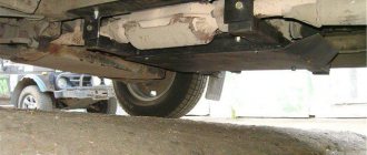
It started with the fact that I got tired of changing the crosspieces, injecting the splines of the cardan shafts, which I then replaced with new ones, and the splines on them were also covered with entrails. I went to 10 workshops to get the RK installed correctly - nothing worked. The hum and ringing of the RK jumping all over the body led me to the FAQ. After reading a lot of smart articles on hanging the RK, I started doing it myself. Result - I drove for 2 months with slightly reduced vibration, and then bang - the intermediate cardan (if that's the correct name) was ruined. I climbed again myself. I removed the gearbox and gearbox and found: Boiled bottom (tear off the master’s hands), half of the bottom is flat (not boiled), the other is at an angle of 60 degrees. And rotten places where the gearbox is attached:
As a result, I went back to the Internet and here is my salvation: Transfer case subframe - but it seemed heavy and difficult to manufacture (you need to look for such a channel), and I didn’t want to drill through the bottom. And the clearance is decreasing, as I understand it’s not bad. But there was a huge plus - there were drawings.
The last 3 were more to my liking, and I, taking a caliper and a tape measure, crawled under my old lady, guided by what I have from the drawings at the last link, which was included in the basis, and the dimensions from the book on Nivka, but also with my own modifications .
You definitely need to measure it on your car.
So, I drew sketches and, based on them, first made a model from wooden beams and plywood, then I corrected the drawings and only after that I sent them to production:
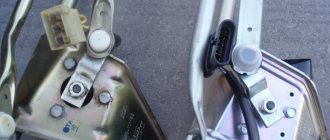
I gave it to a local factory, and they welded me something like this from their material, according to my drawings:
I wore it back and forth 2 times - for fitting (the main thing is that the suit fits):
The height of the structure is slightly less than https://vaz2120.h1.ru/popov/popov.html, which has a positive effect on ground clearance.
ATTENTION. ATTENTION. ATTENTION. ATTENTION.
1) These drawings were developed taking into account the use of a square pipe - 60x30. During the work, it was decided to replace the material with a 40x25 square pipe (this strength is more than enough), while maintaining the axial dimensions. Unfortunately, there is no time to redraw. But at the factory they understood everything anyway.
2) I didn’t turn the bushings into the side members (labor-intensive), but for strength, so as not to squeeze the side member? I placed a plate on its outer side along the length of the subframe, which distributes the load over the entire length, and not pointwise.
Yes, by the way, the project budget was about 600 rubles: 500 rubles. - at the nth plant they welded the entire structure for me, from their material and 100 rubles. for bolts, nuts, etc.
Update dated 05/08/07, by vvv.
The subframe is made of a 60x30 rectangular pipe and 50x50 corners without welding. Everything is bolted on. Fastened with through vertical M12 bolts through the spar. In the interior, under the bolt heads, there are 100x100 mm washers, about 5 mm thick. The design has been on the car for 3 years. The flight is normal.
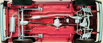
do-it-yourself stretcher on the field photo
There are also some disadvantages, but they are not significant. The ground clearance is reduced, and if you make it yourself, this is quite labor-intensive work.
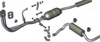
Of course, you can purchase a ready-made subframe, but there are ways to make your own.
The transfer case subframe is made using a sheet of metal, a channel and corners. Download the exact manufacturing diagrams to make all measurements using them. At construction markets you can purchase everything you need.
The connection of the nodes is bolted. To connect the subframe to the field you will need:
– 4 bolts size M12*1.5;
– 4 bolts size 12*1.25.
To work, you need to prepare all the necessary tools. It is best, of course, to do everything on a milling machine. But if this is not possible, then prepare, first of all, personal protective equipment for your hands and face. Next, prepare an angle ruler, a roll, an ink, a hammer, a caliper, a drill with the highest possible power and a small and large grinder.
First of all, we measure all the distances from the base edge of the channel and process it. The thickness of the sidewall wall at the junction with the top flange is 8 mm, so when cutting in the transverse direction, the length of the cut should end at the same distance to the edge of the upper flange of the channel. Transverse windows should be cut out with a small grinder. And the longitudinal ones are big. Once you've cut the windows, you need to chamfer them, but before you do that, you also need to cut out the outline of the side.
Required Tools
First of all, prepare a large and small grinder (angle grinder), a drill (preferably not a battery-powered one), calipers, a roller, a hammer, a ruler, as well as protective equipment to prevent hot metal shavings from getting into your eyes while working with a grinder. All work should be carried out according to a certain scheme (you can see a drawing of the Niva 2121 transfer case subframe in the photo below).
So where to start? First you need to measure and process the base edge of the channel. After this, use a ruler to measure the required distances from it. Windows in the device must be cut out with a small and large grinder in the transverse and longitudinal direction, respectively. The length of the cut should not extend beyond 8 millimeters from the edge of the top flange of the structure. After the windows are cut out, the contours of the sidewalls should be processed and chamfered.
The angle of fastening to the spar and cross member of the device may have a free size, but it should not be less than the length of the mounting holes and the distance between them. If corners are not available, you can use a different scheme for fastening the part to the spar. It is important to maintain the height of the transfer case attachment to the subframe.
If this is a reinforced subframe, then metal corners are additionally welded under the mounting points of the box brackets. The latter are connected to the side parts of the channel. The oblong shaped holes go like a bolted connection.
Subframe drawings for Niva photo
Between the mounting holes, the mounting angles to the cross member and spar can be of free sizes in length and distance. It is necessary to observe the size of the height of the attachment to the subframe, and, by the way, you can use the attachment to the spar of other schemes instead of the corners. You can make two types of dispensers. Basic type and reinforced. In the reinforced version, the ends of the channel are tucked under the fastenings of the transfer case brackets. Also in the reinforced version, the oblong holes for attaching the transfer case brackets are repeated.
The type of connection of the subframe protection is bolted, and is attached at the bottom to the corners. But at the same time, the holes must be threaded in the lower flange of the corners and in the body of the sidewalls of the subframe. To impart strength, sheet protection is used; it forms the part of the structure that forms the box. In order to be able to drain oil, water and trapped dirt, it is necessary to make several holes under the drain plug and between the sidewalls of the channel in any convenient place. To increase protection, it is necessary to attach the corners to the frontal part of the subframe and to the support mount for the box itself. If the subframe is not protected, this may lead to its deformation, as head-on collisions with possible obstacles and tree stumps are possible.
Preparation.
1. After the initial preparation of the elements, finishing processing and connection into a single structure is carried out: 1. In the channel, in accordance with the diagram, rectangular windows are cut out, ending no closer than 0.8 cm to the edge of the edge. Bevels (chamfers) are eliminated;
2. In corners measuring 70x50 or 70x70, holes are made for bolted connections, after which they are tacked by welding.
3. Corners of 35x35 cm are fixed to the lower edge of the channel, to which sheets are welded to protect against impacts and dirt. In the latter, for the purpose of access to the drain plug and regular cleaning, service holes are cut out.3. Corners of 35x35 cm are fixed to the lower edge of the channel, to which sheets are welded to protect against impacts and dirt. In the latter, service holes are cut out in order to gain access to the drain plug and regular cleaning.
Factory design
One of the recommended devices for eliminating transfer case vibration is the so-called “Niva Comfort” kit. The Niva Comfort subframe was developed a relatively long time ago, has a quality certificate, and Niva 2121 owners often use it.
This device is a welded structure made of metal corners, with drilled fastening points, mounting plates to which the base will be mounted. Since the transfer case should not be fixed rigidly to the base, the kit includes elastic supports.
For all its advantages, this subframe for the transfer case has disadvantages. It is installed in the places where the box was previously attached, that is, to the bottom, so if there are problems with the base, installing the Niva Comfort design will be problematic.
Benefits of use
A device such as a subframe has many advantages, the main one of which, as we have already noted, is the reduction of noise and vibrations in the cabin. In addition, this device is the only protection for the lower part of the transfer case.
By the way, on the conveyor the Niva is already equipped with special fastenings to the floor, which allow mounting supports on the transfer case. Thus, installing a transfer case subframe on a Niva will take the car enthusiast no more than 30 minutes. Another thing is to make this part yourself (in this case, the work can take several days). However, why is the car not initially equipped with such a device? To answer this question, let's consider the main disadvantages of the mentioned device.
Homemade design
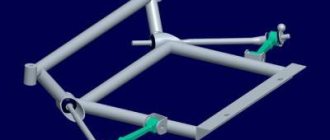
Many people make a similar subframe for the Niva on their own. First you need to make a drawing of the subframe. The simplest design consists of two crossbars and two crossbars connecting them.
The distance between the crossbars should be exactly the same as the distance between the transfer case attachment points to the bottom. Holes are made in the crossbars themselves to which the transfer case will be attached. To strengthen the structure, you can weld braces from metal corners in the inner corners between the crossbars and crossbars.
This design will be attached not to the bottom, but to the side members, so their length must correspond to the distance between the side members. Having made a drawing, you can create this device on the Niva with your own hands. Depending on the wishes of the owner, it can be made collapsible, bolted.
The advantage of such a subframe is the ability to replace a damaged element without removing the entire structure from the car. The disadvantage will be the need to constantly monitor the condition of the bolted connection. The welded structure of the subframe does not require constant monitoring, but if damaged, it will have to be completely replaced.
Next, you need to decide how the subframe under the transfer case will be attached to the side members. It is possible to attach it to the side surface of the subframe. To do this, you will need to drill through holes in the side surface at the mounting points.
The advantage of fixing it to the side surface of the spar is the ability to additionally install silent blocks at the fastening points, which will further dampen vibrations coming from the transfer case. The downside is the need to carry out additional calculations of the diameter of the bolts with which the structure will be attached to the spar, since in this case they will be subject to shear force. A bolt with a diameter that is too small will likely fail quickly due to vibration.
What dangers can await a motorist while driving?
As practice shows, even such a device as a subframe does not guarantee 100% protection for the transfer case and other components of the car while driving off-road. Therefore, if you often operate the Niva in rural areas, where there is a danger of “picking up” a stump or some other object that is difficult to notice in uncut grass, install the special protection on the subframe that we talked about in the previous paragraph. Then the risk of transfer case deformation will be reduced to zero. If there is no such protection, both the subframe and the box itself will deteriorate.
So, we found out how to make a transfer case subframe for a Niva with our own hands. Whether you need it or not - decide for yourself.
Other device mounting options
Installed part on the machine
Another way to secure the structure to the spar involves fixing it to the lower surface of the spar. For this purpose, holes are also made in the fastening points, but only in the upper and lower surfaces of the spar. In this case, you should not particularly find fault with the diameter of the fastening bolt, since there will be no impact on it. But it will be impossible to install additional silent blocks to dampen vibrations.
Another additional element that can be installed on the structure is a special elastic support for the box. It is believed that it allows you to better set the position of the box relative to the gearbox. But in some cases they can do without it. It all depends on the wishes of the owner.
Some car enthusiasts cover this entire structure with a sheet of metal, which additionally protects the transfer case from contamination and possible damage when driving off-road.
The disadvantage of the subframe installed on the Niva is the reduction in ground clearance in the transfer case area.
Installation and Centering
Install and center the transfer case in the following order:
- make sure that the engine mount mounts are installed correctly in the brackets (the centering washers of the front engine mount mounts must fit into the corresponding holes in the side brackets);
- install the transfer case on the car without fully tightening nuts 4 and 5 (Fig. 3-41) securing the transfer case suspension brackets;
- moving the transfer case along and across the body, as well as in the vertical direction, find its position in which the flanges of the drive shaft of the transfer case and the intermediate shaft of the driveline are at the same level, parallel and the gap between them is minimal; The transfer case shafts must be located parallel to the bottom of the body;
- Having installed the previously removed adjusting shims under the suspension brackets (supports), fully tighten the nuts securing the transfer case suspension brackets;
- attach the front and rear propeller shafts to the transfer case shafts; Connect the flexible shaft to the speedometer drive and the wires to the differential lock warning lamp sensor.
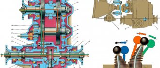
Rice. 3-41. Transfer case installation diagram:
1 — bolts securing the flanges of the intermediate propeller shaft and the drive shaft of the transfer case; 2 — transfer case; 3 — adjusting shims; 4 — nuts securing the transfer case to the body; 5 — nuts securing the transfer case suspension brackets to the axles
When replacing a transfer case or changing a four-speed gearbox to a five-speed one and vice versa, as well as when the rear engine mount settles, causing the transfer case to vibrate, it is necessary to select and install a new thickness of pad 5 (see Fig. 3-40).
The procedure for selecting shims is as follows:
- make sure that the engine mounts are installed correctly in the mounts (see the chapter “Removing and installing the engine”);
- disconnect the flanges of the transfer case drive shaft and the intermediate driveshaft;
- loosen the nuts securing the transfer case supports to the body, remove the adjusting shims and, moving the transfer case along and across the body, as well as in the vertical direction, find its position in which the separated flanges are at the same level, parallel and the gap between them is minimal, and the transfer case shafts are located parallel to the bottom of the body;
- Fill the resulting gap between the body floor and the supports with the required number of gaskets,
- align the centering flanges without creating tension in the transfer case and engine supports and, holding the transfer case in this position, tighten the previously loosened nuts securing the transfer case supports;
- insert and secure the bolts securing the transfer case flanges and the intermediate shaft; if the bolts pass freely into the flange holes, then the alignment is carried out correctly, otherwise repeat the operations to align the flanges.
Shaking problem
Many drivers who have a VAZ 2121 Niva at their disposal have encountered the fact that the cabin vibrates strongly while driving, especially off-road or at high speed. Vibrations that spread almost throughout the entire cabin cause a lot of inconvenience and constant discomfort. Technically, this was not corrected, so the people’s minds had to independently find a way out of the current situation.
After installing the transfer case subframe, the ground clearance will slightly decrease, but the car will be much more comfortable to drive.
Flaws
The main disadvantage of the subframe is the reduction in the vehicle's ground clearance (by several centimeters). But still, this upgrade has virtually no effect on the cross-country ability of the SUV.
The main disadvantage of the subframe is the reduction in the vehicle's ground clearance (by several centimeters). But still, this upgrade has virtually no effect on the cross-country ability of the SUV.
Most likely, the absence of the element in question in the car’s factory configuration is explained by complex production technology (a special
However, no matter how many reasons we name, the fact remains: the transfer case subframe is installed on the Niva only through the efforts of the car owners themselves. Even at service stations, not everyone undertakes their manufacture or installation.