One of the most problematic places in domestic cars is the rear lights of the VAZ 2114. In most cases, the problem lies in low-quality, unreliable rear light circuit boards. As a result, contact with incandescent lamps disappears or is lost over time.
Often the problem is solved by using brute force, by striking the body or base of the lamp. However, such actions do not completely eliminate the problem; periodic failures in the operation of the turn signal, side lights or brake lights occur.
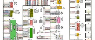
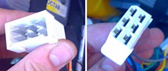
Diagram of wires in chips, rear lights VAZ 2114(08-09-99)-2115
maybe it will be useful to someone. The 4 has the same lights as the VAZ 2108-09-99
Comments 19
I should install this wiring at 21099
Well, you can, take the pinout from the pictures and select it. Everything will be according to color and standards. Just seal the extra wires.
hi, tell me under 1, are these chips also for the lights?
Honestly, I don’t even know, there should be a tag with a number on the wiring, put this number in a search engine and find the diagram, look at the diagram for which wire is responsible for what.
I have a turn from 15 to 14 chips
Everything is in the pictures, take the wires out of the chip and pick them up
I have new chips over them, my contacts are rotten
Well, look, you can’t convert 14k chips into 15k chips since there are 4 of them on 15k. If only to farm
The driver should have a chip under his left foot, and it goes from there to the block.
what color plus rear dimensions? I want to make a light in the trunk
Source
Breakdowns
If the rear headlight unit fails, it is often due to a broken bulb from a particular light, or a problem with the fuses.
A rarer type of failure is a broken wiring.
It should be understood that each element of the rear optics plays its own irreplaceable role, therefore it is necessary to maintain the required level of performance of the optics and promptly respond to emerging malfunctions.
Before long trips, be sure to make sure that all the lamps in your car are working properly. In the event of an accident caused by non-functioning taillights, do not count on insurance. She won't act.
Schemes 2113, 2114, 2115
Electrical diagrams of the Samara 2 family with comments. Some diagrams are taken from the website chipdiagnost.ru
General diagram of the first VAZ-2115
with a regular button for the rear fog lights (with fixation), a fluorescent interior light, a connector for the clock and an 8-pin connector for the injector wiring content-23.foto.my.mail.r…hofer2107/3833/s-3852.jpg The harness is visible carburetor ignition system with a speed sensor; it is not connected to the injector. The 4th wire of the interior lamp is the ignition, so that when the ignition is turned on, the backlight goes out immediately. Peerarm on Ш11 for wipers. On 2109 they are powered through a fuse on the motor (6-pin), here it is not used and therefore there are 5 wires going to the motor.
Years of production 2115: 1997—2012.
Circuit 2115 with “high” panel 21083 is similar to circuit 21099 (except for the rear harness).
General diagram of the VAZ-2115 luxury configuration
with headlight cleaners, heated seats, power windows, central locking, trip computer and fluorescent interior lighting content-5.foto.my.mail.ru…hofer2107/3833/s-3853.jpg
Explanations for the 8-pin injector block:
white-red and blue - for the check light, blue-red - ignition, gray - speed sensor, brown-red - tachometer, blue-white - driver's door switch (for the immobilizer), green-red - K-line (may not be ), green - fuel consumption. Next to it is a pink wire - to the fuel level sensor.
Years of production 2114: 2001—2013
Schemes of individual wiring harnesses of VAZ-2113, VAZ-2114 and VAZ-2115
With a 9-pin square block for the injector, a non-locking button for turning on the automatic transmission, and a starter blocking relay (the injector turns off the starter if the engine is running).
Instrument panel harness
content-20.foto.my.mail.r…hofer2107/3833/s-3834.jpg In the photo there is a relay for the rear fog lights (attached next to the mounting block, the fuse dangles nearby), a button without locking. It works like this: if the low beam and/or front fog lights (if equipped) are on, press and release the button - the automatic transmissions turn on. They turn off when the button is pressed again or automatically when the headlights are turned off, so that the driver does not forget to turn them off.
Glove compartment lighting harness
content-12.foto.my.mail.r…hofer2107/3833/s-3840.jpg There is a magnet on the lid; when it is far from the sensor with the reed switch, the glove compartment light turns on (the reed switch closes the contacts).
Rear harness VAZ-2114
content-18.foto.my.mail.r…hofer2107/3833/s-3842.jpg Rear window wiper motor with pause. When the washer is turned on, it runs continuously.
Additional harness (central locking)
content-20.foto.my.mail.r…hofer2107/3833/s-3835.jpg Connects to the instrument panel, connector next to the hood handle. Pink - door lock, permanent plus, fuse hangs next to the hood release handle. White and black - on the door for electric windows, plus during ignition, switched on through a relay and fuse in the mounting block. Also in the photo is the wiring for the radio speakers.
Seat heating harness
content-1.foto.my.mail.ru…hofer2107/3833/s-3838.jpg The gray wire is connected to the connector where the additional harness is connected (to the gray wire if there is one), plus when igniting, the relay is attached next to the mounting block and The fuse is located next to the hood handle. The white wire is connected to the additional harness, button illumination.
Connection diagram of the mounting block (relay No. 1 - headlight cleaners)
content-10.foto.my.mail.r…ofer2107/3833/s-3851.jpeg In the photo the typo X2-11 is connected to X9-5 (and it says X5-9)
Explanations for the 9-pin injector block:
1 gray - speed sensor, 2 white-red - minus check lights, 3 green - fuel consumption, 4 blue-white - driver's door switch, 5 brown-red - tachometer, 6 pink-black - plus check lights and starter interlock relay, 7 red-black - starter blocking (if there is no minus, the starter circuit is broken), 8 blue-red - ignition, 9 pink - fuel level.
Years of production 2113: 2004—2013
Diagrams of cars from 2011 with an electronic gas pedal (E-GAZ)
The injector comes with a large multi-pin block. Ignition switch from Kalina.
Luxury instrument panel harness (heated seats and seat belt sensor)
content-5.foto.my.mail.ru…hofer2107/3833/s-3864.jpg content-19.foto.my.mail.r…hofer2107/3833/s-3865.jpg The seat heating relay and fuse are located next to mounting block.
Connection diagram of the mounting block (relay No. 1 - fan)
There is a typo in the photo: in relay K1, contact 86 goes to Ш3/8 (and not to Ш8/3). content-12.foto.my.mail.r…hofer2107/3833/s-3843.jpg Briefly about the changes compared to the previous block: relay 1 turns on the engine fan, control goes to the cabin, and from there to the injector. Fuse 1 provides constant power to the electrical package control unit. The headlight wiper chain is made directly.
The rest of the circuits are used as before (rear, doors, heated seats...) Except for the wiring harness of the air supply box. It is used the same, only a jumper is installed on pins 6 and 12 of plug 11 of the mounting block (due to a different connection of the oil pressure warning lamp sensor).
Explanations for the 16-pin injector block:
2 red - battery (on APS), 3 blue-red - ignition, 4 pink-black (plus check lights, starter and engine fan blocking relay in the ChYa), 5 yellow-black - K-line, 6 gray - speed sensor, 7 white-red - minus check lights, 8 pink-red - brake lights, 9 brown-red - tachometer, 10 orange-blue - communication between APS and ECM, 11 red-green - brake pedal sensor, 12 blue-black - diagnostic block from the APS, 13 black-red - minus the engine fan relay in the CYA, 14 pink - fuel level, 16 red-black - minus the starter interlock relay.
And briefly about the changes in the E-gas wiring: The glass heating button is connected to the devices (and not to the stove). The oil pressure light is connected a little differently. In the FC, the engine fan relay is controlled by the ECM (contacts are used that on blocks with 11 relays go to light and dimensions). Ignition switch with a coil (immobilizer sensor), without limit switch and backlight, and the ignition switch works only from the ignition. The ESP relay is connected to the APS (switch-off delay after the ignition is turned off) so that the driver has time to close the windows. APS is an immobilizer, a warning about not turning off the dimensions and turning on the reverse gear, a relay, a door lock block, and somehow it’s all powered from fuse 1 of the mounting block (20 Amperes) to which it is connected in the cabin with a small terminal (Ш3/21), rated at 10 Amperes. But the heavy load occurs only briefly when unlocking/locking the door locks, so everything is fine. A sensor on the brake pedal with two open (to the lights as before) and closed (to the ECM) contacts (when the pedal presses on the sensor), a different connector, there is constant power and ignition, and when the sensor fails (and this is not uncommon ), unnecessary contacts close and the ignition starts working constantly or by pressing the pedal)))))
Photo of what “S” (wire connection) looks like using the driver’s door harness as an example
Source
Connection diagram
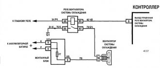
Before troubleshooting, you need to get acquainted with the electrical circuit of their power supply. Let's take a look at the diagram for switching on external lighting devices.
We are interested in:
How it works? When button 6 is turned on, the on-board power supply voltage is supplied to the mounting block. Having passed through fuses F10 and F11, it goes to the control relay K4. Fuses are necessary to protect the power circuits of the left (F10) and right (F11) side dimensions.
The relay controls the correct operation of the side light - if any of the lamps or its circuits malfunctions, it commands the on-board control system 12 to turn on the warning light located on the instrument panel. Having passed through the relay, the voltage is supplied to the side lamps 1 and 8.
Important! In some modifications of the VAZ 2114, instead of the K4 relay, there may be jumpers in the mounting block. Their location in the diagram above is indicated by arrows.
Main causes of malfunctions
Why might the tail light not work? There are quite a few reasons, but we will list them all:
The most common malfunction of the above, of course, is the failure of the side light bulb. In this case, it is enough to replace it. How to do it?
How to change tail light bulbs
Replacing lamps in the rear light of a VAZ 2114 is extremely simple and does not require any tools. We open the trunk lid and opposite the lantern we find this pocket on the upholstery.
Pocket covering the rear light of a VAZ 2114
It's on Velcro. Just pull the edge and open it. In front of us is the back of the flashlight and the power supply.
Carefully remove the block by simply pulling it out.
There are three latches on the lantern: on the top, bottom and side.
We press them out and take out the board.
Place the board face up. The side light bulb is the smallest, marked with an arrow in the photo below.
Slightly recess the lamp, turn it counterclockwise and pull it out of the socket. We install a new one in place of the burnt one, mount the board in place, connect the power supply, and close the pocket in the upholstery.
After replacing the lamp, the side lights do not light up - we are looking for the required fuse
The next fairly common reason that the dimensions of the VAZ 2114 do not work is the failure of the fuse. But before we go to check it, let’s think logically.
Let's look at the circuit diagram (the very first drawing in the article). If fuse F10 burns, the front and rear left side lights, the engine compartment lamp, the instrument panel and license plate lights will not light up. If fuse F11 burns, the starboard front and rear lights will go out at once.
But suppose we have the picture described above. Where to look for fuses? They are located in the mounting block, and the block itself is located in the engine compartment immediately behind the windshield on the driver’s side. In the photo below it is marked with a black arrow.
We open the cover and observe a number of fuses (inserts) and relays. They are all marked, so finding the ones you need won't be difficult. As we remember, we need F10 (left side) and F11 (right side), both rated at 7.5 A.
Opened mounting block with fuses VAZ 2114
Important! We replace the blown fuse with a serviceable one of the same rating. If the value is less, the insert will burn out immediately. If it is more, the insert will not perform its functions and the wiring will burn out if there is a malfunction.
If the fuse is good, what should I do?
But why don’t the lights on the VAZ 2114 light up, even if the lamps and fuses are working? As we found out before, there are quite a few reasons. We will try to find the problem and fix it ourselves.
Let's check the condition of the pads on the lantern and the mounting block. Let's start with the lantern. We disassemble it in the same way as to replace a light bulb (see section “How to change tail light bulbs”). We inspect the block and its counterpart on the board. The contacts must be clean and free of dirt, moisture or oxidation. If it's not in order, we clean it. At the same time, we inspect the socket contacts by removing the lamp: we look for the same thing and, if we find it, we fix it.
Now the mounting block. In order to get to its pads, the device will have to be dismantled, but this is not a difficult task. Remove the cover from the block and disconnect the upper block.
Removing the cover and disconnecting the connector (in the photo there is a VAZ 2109 mounting block with a similar fastening)
Using a 10mm wrench, unscrew the two fixing nuts.
Carefully lift the module and gain access to the pads.
Now the power supplies can be removed and inspected
According to the schematic diagram (figure above), we are interested in the X4 (Ш4) and Х9 (Ш9) pads. They are located as follows:
Location of the pads on the mounting block of the VAZ 2114 car
We inspect and clean if necessary. At the same time, we inspect the rest so that there are no problems in the future. The most convenient way is to pull them all out - this way it’s easier to inspect their mating parts on the mounting block, which you can pick up and take to the light.
The next possible malfunction: the button responsible for turning on the side lights does not work. To check this button, it must be dismantled. You don't need any tools for this. Under the buttons (the side light switch is paired with the low beam switch) there is a decorative panel. We remove it with our bare hands, simply by prying the edges with our nails.
Removing the decorative panel
If on our modification of the VAZ 2114 there is an on-board computer behind the panel, then we remove it too: simply pull it out, turn off the power supply and take it out. Now we put our fingers under the panel, push out the buttons and take them out.
Removed button block
Remove the power supply. Now the button can be ringed with a regular tester set to resistance measurement mode. We will call contacts 1 and 2. They are marked, but to be sure, let’s check the photo, in which the necessary contacts are marked with arrows.
In one position of the button, the device will show zero resistance (when the button is pressed - in the “ON” position), in the other - infinitely large (when the button is in the “OFF” position). If you use an electrician’s tester (sound or light test), then in the “ON” button position the test ring will work (beep or light up), and in the “OFF” position nothing will happen.
Important! Power to the parking light button is supplied directly from the on-board network without any fuses. The slightest carelessness and you will have to replace the burnt-out wiring. Therefore, before such manipulations, it is better to disconnect one of the battery terminals.
Well, the last thing we can do is to carefully examine the harness leading from the mounting block (X9 block) to the rear light. When inspecting the harness, do not forget that the yellow wire is responsible for the rear marker lights on the right side, and the yellow-black wire is responsible for the lights on the left side. During inspection, we pay special attention to the places where the harness passes through the body and its ribs.
It is worth paying special attention to such transition places
If this does not help, then either we did not inspect the harness properly, or the problem is in the mounting block. The only thing that can be done here, without having electrical knowledge, is to try to temporarily replace relay K4. It is installed in a mounting block, its full name is Lamp Health Monitoring Relay (RLL), you should rent it from a friend and look at the result. It worked - we buy a new one, and the problem is solved. If it didn’t work out, you’ll have to contact a specialist or just an electrician you know (not necessarily a car).
So we have sorted out the possible problems with the rear side lights on the VAZ 2114. Let's hope that the knowledge gained will help you solve a similar problem yourself and without going to a car service center.
Source
Recommendations
Comments 28
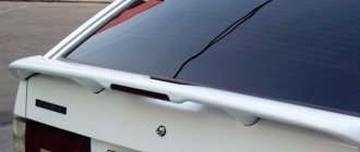
And that’s it., finally)) the mounting block turned out to be working, but still left a new one as a spare, because everything on the old glass heating fuses burned out. I replaced the rear boards and harnesses with wire plugs, all the wiring was rotted in the plugs, and the stop on the spoiler was also replaced with a new one, the old one somehow broke along with all the stops for the company.
Total. Stop in spoiler 250 rub. Boards cost 220 rubles each assembled. Flagella 20 RUR, mounting block from disassembly 1000 RUR.
The new stop spoiler is of much worse quality, the factory one was much brighter. The lamps in the new stop are terrible
We got around to replacing the mounting block with a new one. I rearranged everything and ooooopppppaaaa. The feet still don't work)))
To be honest, I don’t know where to dig anymore...
In the meantime, I’m waiting for my salary, I’ve already gotten used to pressing the rear PTF button when braking))) so that no one will correct my ass))) at least somehow attract attention that I’m braking)))
Still, I decided to disassemble the mounting block and the forecast is disappointing, fuse f4, which seems to be used for heating the rear window, the cigarette lighter and somewhere else, melts the board, everything around it is scorched, the board can’t even be reached, the plastic has already melted to it, next to fuse f3 it is is responsible for the brake lights, perhaps the whole reason is this, how reluctant I am to buy a new unit... but I’ll have to go on a hike. So far I have only treated it with liquid electrical insulation before replacing the unit
That's all we have. all 3 brake lights (spoiler) do not work. The light bulbs are intact, the grounds have been cleaned, the boards are in more or less perfect condition, the tracks are intact, the lamp serviceability relay has been replaced with a new one, the frog is working, the frog is receiving power. for a mystic?))))
In short: in the footsteps, today it was the same, two lamps stupidly burned out at the same time. The spoiler most likely has some wiring cut somewhere. Regarding the turn signal: this is a jamb of the board, either change the lights completely, or just start the car, turn on the lights, turn signal and lightly hit the glass with your palm several times until it is fixed (the contact comes off there). Cleaning doesn't help for long.
stripping does not save for very long. If the weather is rainy or winter, then a month at most (
Check the limit switch (frog) under the brake pedal, it may be damaged. Better yet, buy it and replace it right away, the price is reasonable.
I removed the wires from the frog, shorted it out, nothing lights up, I’ll buy a tester, I’ll have to see if there’s any current flowing to it at all
Check the limit switch (frog) under the brake pedal, it may be damaged. Better yet, buy it and replace it right away, the price is reasonable.
There are 12 V on the wires to the frog, so what?) I shorted the wires, everything is quiet. Let's go to the relay then
And if it burns out, the stops don’t burn? It is also responsible for the fact that if they do not light up, it signals or I do not understand its essence correctly
How can I check the relay? With others, it’s clear they click) should this also be?)))
if it’s burnt, you’ll know by the smell)) and you can open it, there are 2 latches on the sides, you can pry them off and the relay housing will come off
The problem with the blinking of the fog lights along with the turn signals was solved by cleaning the contacts of the headlight. My feet don't still burn. I'm looking at the relay
Are both feet missing? Look at the relay for monitoring lamp malfunctions (the largest in the ChYa) when I paralleled the stops with the PTF, the relay burned out from overload, but yours may have just burned out from a bad ground))
What kind of lamps are in the rear lights of the VAZ 2114
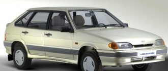
The five-door hatchback VAZ-2114 (LADA Samara) is a restyled model of the VAZ 2109, and therefore the rear lights and lamps in them are practically no different from each other. In both modifications of the VAZ, only two types of light bulbs are used in the rear lights - P21W (A12-21-3) and T5W (A12-5). The first has a power of 21, the second 5 W.
P21W bulbs signal the turn signals, brake lights, reverse lights and rear fog lights. T5W lamps are in size. You will see the location of these lighting devices and their purpose in the photo.
The numbers in the photo indicate:
TECHNICAL DEVICE
In some situations, it happens that the rear lights of a VAZ 2114 do not light up, in other cases only the front ones, but their structure and operating principle are identical. The side lights are located in the turn signal housing, while the front and rear lights find a place in the headlight housing in the same area. There is a special button for the side lights on the dashboard, which allows you to control them; next to it there are headlight switches and other lighting. When the driver touches this button and turns them on, at the same time the corresponding light on the dashboard lights up, which will not allow the driver to forget about the action taken.
Replacing light bulbs
Now let's replace the rear light bulbs. We lift the trunk and look for a valve in the upholstery located opposite this device.
We open the valve (it is on Velcro) and observe the back of the flashlight with the power supply connected to it.
We pull out the block by pulling it towards the central axis of the machine.
Important! The mating part of the block is a metallization applied to a flexible circuit board. We remove the block carefully, since if the pulling is unsuccessful, the entire board will have to be replaced.
We release the latch located on the side of the lamp that is located closer to the center of the machine, and remove the board along with the lamps.
We unfold the board with the bulbs facing up and observe the picture shown in the photo in the first section of the article. All lamps are removed in the same way - by turning them counterclockwise. We find the burnt out lamp and replace it with a new one.
Connection diagram
The rear lights on the VAZ 2114 are connected to the vehicle’s on-board network using connectors, the pinout of which is given below.
The numbers in the photo indicate:
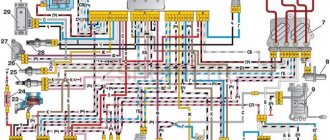
Both lights are connected to one harness, which runs along the rear of the body from the right light fixture to the left, then along the left side to the mounting block located in the engine compartment immediately behind the windshield opposite the driver. The complete wiring diagram of the electrical equipment of the VAZ 2114 (injector) will look like this:
In this scheme we occupy the marked positions:
Tail light repair
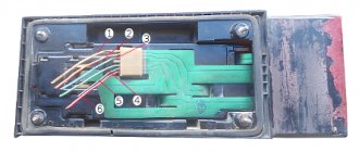
The most common reason for the failure of a VAZ 2114 rear light is the failure of a flexible printed circuit board or a connector made directly on it with conventional metallization. You can, of course, just buy a new printed circuit board and replace the faulty one with it, but, firstly, for how long?
And secondly, we are not looking for easy ways. So we will try to eliminate this malfunction on our own, at minimal cost and in such a way that it will last forever. Let's start with the connector for connecting the flashlight to the on-board network. It looks something like this:
The connector for connecting the rear light to the on-board network is part of a flexible circuit board and cannot be replaced separately
There are many reasons for this connector to fail. For example, we removed the power supply from the flashlight too often and simply partially erased the traces, which have a very small thickness of copper deposition on the plastic. Another reason is that the conductive paths next to the connector broke due to constant vibration. Well, the most banal thing is that the tracks burned out due to overload or short circuit.
The photo shows a flashlight connector of a different modification, but the meaning of the problem is the same. All these issues can be solved with the help of a soldering iron, mounting wire and a regular six-pin (or more) connector with a mating part.
We clean the connector contacts on the board using a student eraser (not sandpaper - the foil is very thin!) and service them.
You need to tin the tracks very quickly with a well-heated soldering iron. Otherwise, the tracks will simply fall off the substrate.
We solder the wires from the block onto the tracks, not forgetting to mark them, and fill the soldering area with sealant or a hot glue gun.
We cut off the standard power harness block, and in its place we solder the mating part of the new one. We assemble the flashlight, connect it to the on-board network - and check it. If we haven't messed up the wiring of the pads, then everything will work right away with a bang.
What to do if the tracks are burned out or broken? You can get out of this situation as follows. Immediately after the fracture, we clean the protective varnish from the tracks, tin, and solder the block. It will look like this:
You can, of course, limit yourself to this (until next time), but if you spend a little more time and effort, you can make more serious repairs. Flashlights modified in this way will serve faithfully for many years. Such a repair will save you from the eternal problem of contacts of flimsy standard sockets - this is also a very common malfunction of VAZ 2114 headlights.
To implement this idea, in addition to the six-pin block with a mating part (see above), you will need five cartridges from the VAZ 2106 direction indicators and a dozen terminals for them.
We remove the lamps, standard sockets and flexible printed circuit board from the panel. We place the purchased cartridges in the right places on the panel and mark their centers. Special precision is not required here, the main thing is that each lamp shines into its own “window”. We drill holes according to the diameter of the base parts of the cartridges.
We insert the cartridges into the holes, mark the mounting holes, drill them, and screw in the screws. Now the cartridges are firmly fixed in the panel.
Using a mounting wire with terminals pressed onto it (you can crimp it with ordinary pliers and solder it to be sure), we assemble a circuit that repeats the layout of a standard flexible printed circuit board. To be sure, the terminals can be insulated with heat-shrinkable tubing, but in principle this is not necessary - the panel on which the cartridges are mounted is plastic. We solder our block to the ends of the wires.
We solder the mating part of the block to the power supply harness of the lights, having first cut off the old one. We solder it, not twist it together. The twist will oxidize in a week, and problems will begin again - sometimes it burns, sometimes it doesn’t. We insulate the solder joint with heat shrink or cotton (black rag) tape. PVC electrical tape is an extremely bad option. It can unfold over time. This kind of isolation is no good.
We admire our work for a couple of minutes, insert the lamps, connect them, check them. Is everything working as expected? We assemble the lantern and connect it.
Adapter
Alas, the quality and efficiency of the standard cabin filter provided for the VAZ 2114 leaves much to be desired.
Essentially, it is a strip of filter material that is located between two plastic grilles. The effectiveness of this design is insignificant, which forces car owners to take certain measures.
The best measure is to install a filter adapter. Making it yourself is not difficult, although there are other ways to obtain this design.
Adapter drawing example
Thanks to the adapter, it becomes possible to install a truly effective air purifier for the cabin, which retains the smallest particles and does not allow the driver and passengers to breathe dust.
Externally, the adapter is an improved housing for the interior ventilation system with a filter built into it. The design consists of two elements - the rear and the front. A filter is inserted into the rear component, and the joints between the adapter parts are sealed with rubber gaskets. This ensures the necessary tightness. The design nuances will allow you to avoid moisture penetration even when washing the car.
Article on the topic: How to properly start a car from a pushrod: injector and carburetor
When planning the installation of the adapter, experts strongly recommend using a pleated cabin filter borrowed from the VAZ 2110.
The simplicity of the adapter design makes it possible to replace the filter with your own hands in the shortest possible time. And during installation you do not have to remove the heater. So this is an ideal solution to significantly improve the ventilation system of your VAZ 2114.
Options for obtaining an adapter
If you have made the right decision that you want to get an adapter for your VAZ 2114, you need to decide how exactly you will get it.
There are three main options for this.
You should start making your own adapter only if you are completely confident in your own abilities. Spend the money you save on purchasing a high-quality carbon filter from a VAZ 2110.
Making the adapter
The instructions for creating an adapter with your own hands are quite simple. Another question is how accurately you can implement your plans.
- Find diagrams to create an adapter. Now there are many of them on the Internet. Just keep in mind that you need an adapter specifically for the VAZ 2114.
- Make a layout out of paper so that you understand exactly where each part goes and how they are connected to each other.
- Stock up on the required amount of stainless or galvanized steel. Some people use plastic, but it is a little more difficult to work with, plus it can cause problems when getting bends.
- Cut out the necessary adapter elements from the material, guided by the drawing and layout.
- Use a vice and mallet to make bends. The walls will be thin, so do not use a metal hammer. It is better to take a wooden or rubber mallet.
- The parts are connected using M3 bolts or rivets.
- The advantage of rivets is that you do not need to drill holes in the metal. But they also have a drawback - a high probability of damage to a thin sheet of metal.
- At the last stage, carefully treat all joints, connections and holes with sealant. This will allow the structure not to make unnecessary noise while driving.
Article on the topic: H4 lamps on the VAZ 2114: why halogen, lamp test, all-weather models
Finished design
The manufacturing process will take at least 6 hours. Plus, you will additionally have to spend time studying diagrams, drawings and creating a layout. So be patient.
What and how can you change the standard lights?
The easiest way is to change the appearance of your car - replacing the light fixtures with more original ones. The range of flashlights for the VAZ 2114, of course, is not particularly wide, but there is plenty to choose from. And the simple way is because all tuning comes down to “removing the standard ones, installing the purchased ones.” Let's wander around the shops and see what we can find for our VAZ 2114.
Osvar flashlights are the most popular option among car enthusiasts. They are relatively inexpensive and finding them is not a problem. The only thing is that the manufacturer uses ordinary light bulbs in it, but if desired, you can replace them with LED ones yourself. Although for most car owners this is not relevant.
Skyline style . Also a “lamp” option, but it looks completely different.
Tail light Skyline style for VAZ 2114
ProSport RS-02020 . This is already an LED option. True, the light bulbs responsible for the different signals in them are clearly not in their places, which may not please other road users, and the traffic police inspector will definitely not understand you.
ProSport RS-02020-T . The same “ProSport” with mixed up signals, but with tinted windows. A real gift to the traffic police!
Tail light ProSport RS-02020 with tinted glass
ProSport RS-07490 . Option with light bulbs. Same manufacturer, same misunderstanding - the turn signal is located between the marker and the brake light. You can't make it up on purpose.
"Zigzag" 0013L . This LED miracle is offered by manufacturers from Togliatti, the birthplace of the VAZ car. Here at least the signals are more or less in place.
Tail light "Zigzag" 0013L
We'll finish our shopping trip here, although there are still many miracles there. Just watch a short video about a flashlight with red turn signals and move on to the next point.
How to remove tail lights
It's time to figure out how to remove the stock lights to install new ones. To work, you will need an 8 socket wrench with an extension and a Phillips screwdriver. We open the trunk door, use a Phillips screwdriver to dismantle part of the upholstery so that, by bending it, you can gain access to the entire rear part of the lamp.
The upholstery is attached to the body using self-tapping screws
We find 4 nuts around the perimeter of the light fixture and unscrew them with a wrench
The lamp is secured with four nuts
Carefully remove the connector by pulling it towards the central axle of the car. We don’t swing it, we just pull it, trying not to twist it!
Removing the power supply
Pull the light from the outside of the car toward you and remove it.
Now the lamp can be removed
We install the new light fixture in the reverse order.
Replacing the headlight glass
If you see that the headlight itself is working, and its cloudiness is due to glass defects, you need to know how to remove the glass from a VAZ 2114 headlight and then replace it.
Headlight glass
The algorithm for performing the procedure is as follows:
- We dismantle the headlight using one of the methods described above.
- Take a thin flat screwdriver (spatula, knife) and pry up the corner of the glass.
- Insert the tip of a utility knife into the resulting gap and cut through the old sealant (if there is a lot of sealant left, take a hairdryer and heat the edges of the glass).
The glass is now removed, but remember that reassembly will involve applying sealant (can be replaced with a rubber seal), so be sure to get some in advance. Also, some manufacturers' headlights have headlights with clips, so don't use brute force, just look where they are and tighten them.