Do-it-yourself valve adjustment on a VAZ 2109
The design of the engine on VAZ 2109-2108 cars is such that it is sometimes, although not often, necessary to adjust the valve clearances. Of course, this procedure is slightly different from the VAZ “classic” models, since in this case it is necessary to select the thickness of the adjusting washers. It is because of this that this operation is a little more labor intensive. Also, to perform this type of maintenance, you will need a special device, the so-called rack. A more complete list of required tools is given below:
- adjustment device
- ratchet and socket 10
- long-nose pliers or tweezers
- Phillips screwdriver
- set of flat probes
- shims
Before you begin this procedure, you must complete the following preparations:
It is also worth keeping in mind that the described adjustment work must be carried out at an engine temperature of no more than 20-25 degrees, that is, completely cold (in the summer).
The video below shows the entire process most clearly. I wrote all this down just a few days ago, and tried to make everything accessible and understandable to everyone. The review was made using the example of an 8-valve injection ten, but there is no difference between the 2109, even if it is a carburetor model (the only differences are in removing the valve cover).
And for those owners who are accustomed to text information, everything is described below in exactly this way with explanations in pictures, according to the principle of many official repair and operation instructions.
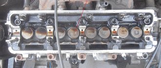
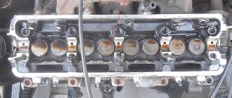
So, when the cover is removed and the timing marks are set, then at this moment you can measure the thermal clearances between the pusher and the valves: 1, 2, 3, 5. Make sure that the camshaft cams on all valves are facing up. The clearance on the intake valves is considered nominal at a value of 0.20 (+-0.05) mm, and on the exhaust valves 0.35 (+-0.05) mm. If you look at the engine from the front of the car, the valves are arranged like this: exhaust-intake-intake-exhaust, and so on.
If the gap differs from the optimal value, it is necessary to select the correct size washer. That is, simply put, if the washer was 3.45 mm in size, and the gap for the intake valve was 0.30 mm, then the new washer should be 0.10 mm thicker, that is, = 3.55 mm. I think the meaning is clear!
Now in more detail about how to remove the adjusting washer from the pusher. To do this, install a special rail on the valve cover mounting studs and secure it with nuts. This is clearly shown in the photo below:
Now we press the valve down using the levers and place the stop that comes with the rack in order to fix the pusher in the pressed state:
Then you can use tweezers or long-nose pliers to remove the adjusting washer:
Let's look at its thickness:
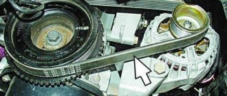
And we select the required thickness using the method described above in the article. After all 4 valves are adjusted, you can proceed to the other four. To do this, you need to turn the crankshaft of the VAZ 2109-2108 one full turn. This can be seen by the mark on the flywheel through the hole in the gearbox housing. It is convenient to rotate the crankshaft as follows:
- hang up the front wheel
- put the gearshift lever in fourth gear
- and turn the wheel with your hand (you can even use your foot), while looking at the mark on the flywheel
When the crankshaft has made one revolution, you can begin adjusting valves 4, 6, 7 and 8. We do everything by analogy. Upon completion, install all the removed parts in place and start the engine. Be sure to wait until it warms up and listen for any extraneous knocks. If everything is normal, the car starts well, there are no problems with the engine, no knocks are detected, then the job is done successfully!
If you have any questions, ask them and we’ll try to solve them together!
We recommend reading:
What is the function of valves
Valves are an indispensable part of the gas distribution system of each electric motor. The camshaft, rotating by means of a belt, chain or gear, crankshaft, or special cams, opens and closes various valves at the required moment.
During the intake stroke, the intake valves are open, during the compression and operation stroke all valves are closed, and during the exhaust stroke, the exhaust valves are open.
Through the intake valves, an air-fuel mixture (carburetor and injection internal combustion engines) or air (diesel and direct injection) enters the engine. When exhaust occurs from the combustion chamber, fuel combustion products leave.
Therefore, the valves heat up and become wider. The thermal gap allows the valves to function optimally.
Adjusting valves 2109, replacing them and adjusting clearances
Lada Vesta Logbook 5. Installed 17th wheels
Adjusting the valves of the VAZ 2109, its technology and features, is of interest, naturally, only to the owners of this VAZ model. However, the principle of operation is universal and familiarization with it will not hurt anyone.
How to adjust valves 2109?
Video tips for adjusting valves on a VAZ 2109
In internal combustion engines, which are installed in cars and other cars, a fairly large number of parts are made in such a way that the thermal expansion of the metal in no way affects their performance. First of all, this concerns the thermal gaps between the timing valve stems and the elements exerting pressure on them. Which experienced car enthusiast does not know the procedure for setting valve thermal clearances?
Adjusting the valves is also inevitable, because thanks to this procedure you can achieve fuel economy, get maximum power from the engine and simply have a comfortable ride. Everyone knows that when the gap is increased, a characteristic annoying ringing comes from the motor.
Adjustment of valves 2109 is necessary to ensure that there is a thermal gap between the end of the valve and the cam - 0.2 mm for the intake valve and 0.35 mm for the exhaust valve. The error during regulation should not be more than 0.05 mm. If the gap is too large, the valve does not open completely, as a result of which not all of the fuel mixture enters the cylinder, and the exhaust gases are poorly removed. There is no gap, which means the valve does not close the window.
What do you need to know if you need to adjust the VAZ 2109 valves?
Valve adjustment - video
The design of the gas distribution mechanism in cars of the ninth series is significantly simplified in comparison with “classic” Zhiguli engines. The camshaft lobes apply pressure directly to the end of the valve through the adjusting plate. There are no rocker arms or other transmission elements here. Sets of washers of various thicknesses are available for sale. Regulating the thermal gap comes down to choosing a washer of the required thickness.
The gap size is determined using special calibrated probes, which are also commercially available. In addition, you will have to purchase a special device for recessing the valve pushers, because without it it is impossible to remove or install the washer. Such an acquisition will not be superfluous, because regulation is carried out after the VAZ 2109 valves have been replaced and after a mileage of 25 - 30 thousand km.
At the stage of preparation for adjustment, it is also necessary to perform several operations:
- Prepare a set of keys and a jack;
- remove the cover and the carburetor air filter;
- install a device for recessing the pushers on the head.
Features of the technological adjustment process
First, you need to determine which of the valves are inlet and which are exhaust, because their gap sizes are different. That is, we need to know elementary . Counting from the camshaft drive, the exhaust valves are located in the order: 1-4-5-8, and the intake valves: 2-3-6-7.
The clearance can only be adjusted when the camshaft cam is at the top and the valve is completely closed. This can be achieved by turning the camshaft.
First you need to align the marks on the sprocket and the drive cover. The piston in the first cylinder will be at top dead center, from which it will be necessary to rotate the shaft 45 degrees (+2-3 teeth). It is better to write down the adjustment procedure on a sheet of paper in advance.
The adjustment itself occurs as follows. A feeler gauge of the appropriate size is inserted between the washer and the camshaft (the feeler gauge should enter with little resistance). If it fits in without difficulty or, conversely, does not fit into the gap, the washer must be replaced. We recess the pusher and insert the lock so that it does not interfere with the removal of the washer. The washer is removed from the pusher and another one (thicker or thinner) is installed in its place. The thickness of the washer is written on one side.
Experienced drivers can figure out which washer needs to be installed the first time, but this skill only comes with practice. All other car enthusiasts are doomed to insert and remove washers of different sizes until the required gap is set.
Replacing seats
The replacement procedure consists of two important procedures: removing old parts and installing new ones.
Removing old planting elements
Replacement of valve seats is carried out on a dismantled cylinder head with a disassembled gas distribution mechanism. You can remove the old ring using a welding machine, if the material from which it is made allows this.
To perform the procedure, a valve seat remover is made - an old unnecessary valve is taken, the plate of which must be machined to the size of the inner diameter of the seat.
After this, the resulting tool is recessed into the seat, 2-3 mm short of the edge, and “grabbed” by welding in 2-3 places. Afterwards, the valve along with the metal ring is knocked out from the back side with a hammer.
Valve seats made from non-weldable metals can be removed by screwing a piece of pipe into the seat as a valve seat remover. To do this, a thread is cut on the inner surface of the ring. A similar thread is applied to the outer surface of a metal pipe of suitable diameter.
An old valve is taken and first welded to the end of the pipe in the reverse position. In this case, the valve stem is inserted into the hole intended for it, the pipe is screwed into the thread, after which the element is removed by tapping the stem.
Installation of new saddles
Before starting the installation procedure of new saddles, the seats under them are cleaned of dirt. After the cylinder head should be heated evenly to a temperature exceeding 100˚C. At the same time, the metal expands, allowing the ring to be pressed in.
The mounted part is cooled using liquid nitrogen. In its absence, you can use a combination of ice and acetone, which allows you to reduce the temperature of the metal to -70˚C. The dimensions of the parts are selected in such a way that the difference between the diameter of the seat and the ring is no more than 0.05-0.09 mm on cold parts.
The valve seat is pressed into place using a special mandrel or a piece of pipe of suitable diameter. The part should fit into the seat with little effort
In this case, it is important that the ring fits without distortion
After pressing in and cooling the cylinder head, you should check whether the element is loose in the seat. If there is no gap and the replaced element is held tightly in place, the replacement procedure can be considered complete. Next, you need to trim the valve seats using cutters.
Adjusting washer
I installed a tachograph with CIPF But in vain 1214, January 26, 2022 Print version
Then remove the steel bushing and adjusting washer, after which the trigger sector is carefully removed from the stop.
The outer end of the latter is clamped in the pocket of the adjusting washer 7, mounted on the fixed cover o. Concentric slots in the places where washer 7 is attached allow it to be rotated when adjusting the device. The reohord is included in the measuring circuit of an electronic bridge of the EMD type.
When installing the kingpin support bearing and adjusting washers, it is necessary to ensure an interference of 0 1 mm in the M 20 and Moskvich-400 cars, in the GAZ-5 car - with a gap of no more than 0 15 mm, in the ZIL-ISO car - 0 10 mm.
| Starter connection circuit for checking. |
The required amount of axial clearance is ensured by installing adjusting washers on the armature shaft journal on the drive side.
This gap should be equal to the thickness of the adjusting washer 2 plus the working stroke of the punch equal to 0 45 - 0 5 mm.
The axial clearance of the sector shaft is regulated by selecting an adjusting washer of a certain thickness.
Low pressure injection burners, which have an air adjusting washer, ignite with low gas pressure and a closed washer. During the ignition period, combustion occurs due to the secondary air available in the furnace of the unit. When torches appear at all burner fire holes, the gas pressure rises slightly and the air washer slowly opens. If the gas combustion is stable, the operator, observing the flame, alternately increases the gas pressure and opens the air washer until a mode is established that corresponds to the operating instructions.
Medium pressure injection burners, which have an air adjusting washer and ceramic combustion stabilizers, ignite with reduced gas pressure and a closed washer. Gas during this period also burns due to the air available in the firebox. If there is a stable flame at the burner mouth, the gas pressure rises slightly and the air washer slowly opens so that the stability of the flame is not disturbed. The transition to the design gas pressure mode and the supply of primary air in an amount that ensures complete combustion of the gas is allowed only after the ceramic stabilizer has been heated to a light red heat. With stable combustion stabilization using a ceramic slide or divider, the torch should come off the burner mouth and the gas should burn on the surface of the stabilizer. If a ceramic tunnel serves as a stabilizer, then the gas mainly burns in the tunnel and the flame should not be separated from it.
The air bubble is installed in the center of the scale using adjusting washers. Ball tilt indicators are installed on MKA series cranes. A steel ball is placed in a plastic case with a spherical bottom, hermetically sealed with a plexiglass lid and filled with oil. When the crane operates on an uneven site, the ball moves along the spherical bottom, indicating the slope of the crane. The pointer scale is backlit. Verify the pointer in the zero position of the ball using special screws, having first installed the tap on a strictly horizontal platform.
| Liquid tilt indicator. |
The air bubble is installed in the center of the scale using adjusting washers.
Disassembling the glass, selecting the total thickness of two adjusting washers, assembling the glass and checking the selection of washers are carried out in the same way as on a GAZ-51A car.
During the adjustment process, an additional weight in the form of an adjusting washer is placed under the balance screws for final balancing of the balance.
Correct tightening of the bearings is achieved by installing steel shims of different thicknesses or by grinding.
Why do you need a throttle washer for heating?
Without the use of throttle washers, heating a large number of objects becomes impossible. The standard diameters of industrially produced water pipes do not allow for correct hydraulic conditions in the main heating network. The buildings closest to the heat source will consume too much thermal energy, while the most distant enterprises will not receive enough of it.
Appearance of throttle washers Source Ttd.market
To avoid this, heat supply organizations require the installation of throttle washers that limit coolant flow in accordance with the size of the object and its thermal power. This achieves several goals simultaneously:
- the temperature in the premises of the heated facility is within the limits of legal standards and is comfortable for humans;
- coolant flow in the system becomes predictable, which makes it possible to correctly configure heat generating units in boiler rooms;
- the presence of a throttle diaphragm forces the owner of the facility to maintain the internal heating system, otherwise the temperature in the premises will be below normal, and the temperature of the return pipeline will be too high, which is a reason for a fine.
In addition, facility owners can install repeat throttling washers, regulating the coolant flow inside the facility.
The simplest drawing of a throttle washer Source Opechkah.ru
Where does valve adjustment begin?
Do-it-yourself valve adjustment on a VAZ 2107
The thermal gap is adjusted after measuring it, and if it does not correspond to what is required, by selecting a washer of a certain thickness.
Next, we will consider the procedure for adjusting the thermal gap on a VAZ 2114. All work is not very complicated, but requires certain equipment. To complete the work you will need:
- set of open-end wrenches;
- spark plug key;
- set of probes;
- special device for squeezing valves;
- set of adjusting washers;
- rags;
The set includes a set of washers with thicknesses from 3.0 mm to 4.5 mm. The thickness size interval is 0.05 mm, which allows you to select a washer of the required thickness when performing work. This set is not cheap, but purchasing it will allow you to carry out all the work yourself for a long time, without going to a service station.
Also, to complete the work, you will need a valve cover gasket, since it is disposable and must be replaced when the cover is removed.
Purpose
The throttle plate performs one specific task - heat distribution in the heating system. It is also responsible for regulating pressure so that the entire system does not malfunction. They are manufactured according to predetermined strict parameters and tested before use. Traditional washers have one threaded hole in the center and are installed in a specific location in the structure.
If the parameters change, a complete recalculation and installation of all key elements will be required, so repairing the coolant may take several days.
Valve drive clearances, do-it-yourself adjustment VAZ 2113-2114-2115
- Valve drive mechanism
- 1 – cylinder head
- 2 – valve
- 3 – pusher
- 4 – camshaft bearing housing
- 5 – camshaft
- 6 – adjusting washer
- 7 – oil deflector cap
- A - gap between the cam and the adjusting washer
- In order to replace the adjusting washer, it is necessary to recess the valve tappets
- 1 – special device
- 2 – pusher.
When the engine is cold, the gap between the washers and the camshaft cams for the intake valves is 0.2 plus minus 0.05 millimeters; for the exhaust valves of the VAZ 2114 it should be 0.35 plus minus 0.05 millimeters. The gap can be adjusted using the thickness of the shims.
Adjusting washers are produced in thicknesses of 3-4.5 millimeters, with an interval of 0.05 millimeters; the marking of the adjusting washer is indicated on one of its surfaces.
Steps for adjusting gaps:
- – Remove the valve cover and timing belt protection of VAZ 2113, 2114, 2115, Lada Samara 2.
- – Remove the spark plugs and wipe the engine oil from the top of the cylinder head.
- – There should be no chips or cracks on the surface of the camshaft.
- – Mounting studs should be installed on the cylinder head cover of the Lada Samara 2.
- Checking the timing marks on the camshaft pulley and rear timing belt cover
- – Rotate the crankshaft until the timing marks on the pulley and the rear cover of the timing belt coincide, and then you need to turn it 40 to 50 degrees (equivalent to 2.5-3 teeth on the camshaft pulley), so that the combustion phase is in the first cylinder.
The crankshaft must be turned clockwise. The crankshaft can be grabbed by the generator drive pulley bolt. The crankshaft can also be turned by the camshaft pulley using a special wrench. In this case, the crankshaft must not be turned by the camshaft pulley, as this may damage the bolt.
– It is necessary to check the gaps at the first and third camshaft cams of the VAZ 2115 with special feeler gauges.
- In order to replace the adjusting washer, it is necessary to recess the valve tappets
1 – special device
2 – pusher.
- After the pushers have been recessed, it is necessary to fix them and replace the adjusting washer
- 1 – latch
- 2 – adjusting washer
- – When replacing the adjusting washer, it is necessary to recess the pusher, then fix it.
- – Using a special tool, remove the adjusting washer and measure it
- – The thickness of the washer is determined by the formula:
- H = B + (A - C)
- where A is the measured gap in millimeters
- where B is the thickness of the washer in millimeters
- where C is the nominal value of the gap in millimeters
- where H is the thickness of the new washer in millimeters
– Having installed the adjusting washer, it is necessary to remove the clamp and check the gap; if the gap is correctly adjusted, the feeler gauge, the thickness of which can be from 0.2 to 0.35 millimeters, should enter with slight pinching.
– You should strictly follow the sequence of adjusting the clearances, sequentially turning the camshaft by 90 degrees, the clearances of all Lada Samara 2 valves are adjusted.
Angle of rotation of the crankshaft from the position of the combined marks, degrees
Preparing for regulation
Allow the engine to cool before starting repair work.
The temperature for adjusting the valves should be no more than 20 degrees. To work you will need the following tools:
- set of wrenches;
- screwdriver;
- tweezers;
- puller;
- measuring probe;
- adjusting washers;
- gaskets for 8 valves.
Set the car to the handbrake, lift one of the front wheels with a jack - this will allow you to turn the crankshaft, and then engage 5th gear.
After this, follow the sequence of actions:
- Disconnect the pipes from the valve covers and remove the air cleaner. Then disconnect the throttle drive cables from the carburetor.
- Unscrew the two nuts, remove the cover and remove any remaining oil. Remove the timing belt cover.
- Place the piston of cylinder No. 1 at TDC on the compression stroke.
Step by step instructions
- The gap on the intake valve should be 0.2 mm - an error of 0.05 mm is allowed.
- The gap at the outlet should be 0.35 mm - an error of 0.05 mm is allowed.
- keys;
- a device that retracts valve pushers - costs about 100 rubles;
- set of probes;
- micrometer;
- adjusting washers - they have a thickness from 3 to 4.5 mm. They come with an interval of 0.05 mm. That is, you can find washers in sizes 3.05 mm, 3.1 mm, etc. up to 4.5 mm. (one puck costs about 20 rubles).
- retract the pushers and fix them in the lowest position;
- remove the adjusting washer and use a micrometer to measure its thickness;
- determine the thickness of the washer that you need so that the gap becomes normal (how to do this is written below);
- take a washer of the required thickness and place it in the pusher with the side on which the thickness of the washer is written;
- Check the gap again.
- 5 (outlet) and 2 (inlet);
- 8 (outlet) and 6 (inlet);
- 4 (outlet) and 7 (inlet).
Effect of installing washers
Installing a throttle washer solves not only the problems of the external hydraulic network, but also the internal system:
- The most distant heating risers are provided with sufficient coolant flow and are well heated.
- The objects closest to the central heating point do not overheat, the air temperature in the rooms remains comfortable.
- The system is in a stable and predictable hydraulic mode, sudden changes in its parameters are excluded: flow, pressure, temperature, etc.
- The temperature in the supply and return pipelines corresponds to the approved temperature schedule, thereby reducing the cost of the produced thermal energy.
- For consumers of superheated water and steam, guaranteed conditions are created for maintaining absolute pressure under dynamic thermal operating conditions of the network.
- For subscribers operating heating systems, conditions are created to maintain pressure in the pipelines at a level not lower than 5 kgf/cm2 at any point in the branched network, which helps prevent boiling of the coolant, or, conversely, the formation of a vacuum.
An individual heating point is the heart of the heating system of any building Source Dvesk.ru
Step-by-step adjustment
Checking and adjusting valves is a simple job that everyone without exception can handle if they follow the instructions exactly:
- First of all, you need to remove the cover from the cylinder head.
- Remove the protective front cover from the timing belt.
- The candles are unscrewed. For more convenient unscrewing of spark plugs, it is recommended to use an open-end wrench of the appropriate size.
- Excess automobile oil is carefully removed from the top of the head.
- The integrity of the cams is carefully inspected. If during inspection any defects are found on these elements, they must be eliminated.
- A special device is installed on the studs to which the head is fixed to help recess the pushers.
- Next, you need to turn the crankshaft strictly clockwise until the mark on the rear cover of the timing belt and the pulley coincide. After the mark matches, you need to rotate the crankshaft 50 degrees.
- Using a set of feeler gauges, the clearance of the 1st exhaust valve and the 3rd intake valve is checked, the count should be taken from the pulley.
- If the gap dimensions correspond to the indicators that were previously given, then the following is done:
the pushers are recessed and fixed at the lowest point; the washer for adjusting the gap is removed and its thickness is measured using a micrometer; Having decided on the desired thickness of the washer, you need to take a suitable element from the kit and install it in the pusher
In this case, it is important to ensure that the washer enters the pusher with the side on which its thickness is indicated; The gap dimensions are re-checked.
- The remaining valves are adjusted according to the same scheme, each time you need to turn the crankshaft half a turn, and the adjustment sequence should occur in this order:
- 2nd inlet and 5th outlet;
- 6th inlet and 8th outlet;
- 7th inlet and 4th outlet.
Throttle washer installation location
In the vast majority of cases, the throttle washer is installed on the second flange of the inlet valve of the supply pipeline in the direction of movement of the coolant. Such a procedure is activated and recorded by officials of the heat supply organization and the owner of the facility.
The throttle washer is installed in the flange of the inlet valve on the supply pipeline Source Sdelai-lestnicu.ru
If necessary, repeat washers can be installed in order to adjust the hydraulic conditions inside the object. In this case, the inlet throttle diaphragm will strictly limit the coolant flow, regardless of the number of washers installed after it.
In some cases, to protect heating radiators from excess pressure, washers are installed on both the supply and return pipelines of a given section of the heating system.
As a rule, all washers are installed in the premises of an individual heating unit. If there is an elevator, the washer is not installed, since the nozzle of the mixing unit performs the same functions - limiting the coolant flow.
The elevator unit does not require the installation of a throttle washer Source Ukcet.ru
Valve clearance adjuster
A more effective and efficient way to adjust the valve mechanisms of the power unit is to adjust them using a device, which is a special rail with an indicator attached to it. This adjustment is much more accurate manually, since when using the device, it detects and takes into account all defects on the surface of the adjustable parts.
For mechanical adjustment, in addition to dismantling the cylinder head cover, you will additionally have to remove the accelerator drive, the protective shield on the ignition distributor, the exhaust hose from the crankcase, and for carburetor cars, the carburetor “pan”.
Using a special wrench, you need to rotate the crankshaft until the marks on the camshaft sprocket align (this is described above). To make this process easier, you can use a bright marker to mark the camshaft sprocket every 90 degrees. After that, we install the device rail on the valve being tested and fix it in a stationary state. We put an indicator on it and place its foot on the edge of the adjustable valve. To correctly perform this procedure, you will need a special grip, with which you need to clamp the cam and pull it up (a simple wrench will do). As a result, the indicator readings should deviate by 52 divisions. If they are slightly too low or too high, the valve needs to be adjusted. And then everything is extremely simple:
- using a 17mm wrench, loosen the locknut on the adjusting screw;
- the gap is adjusted with a key of 13, and all readings are clearly reflected on the indicator scale;
- the adjustment is checked and the locknut is tightened;
- At the end of the stage, it is again necessary to check the correct settings of the valve mechanism.
As you can see, this adjustment is much more accurate and simpler. But we should not forget that a highly qualified specialist will perform it at a high level and using a standard set of probes. In conclusion, it is worth emphasizing that most sets of feeler gauges contain an adjustment diagram that contains data on the angles of rotation of the camshaft and crankshaft, indicating the numbers of cylinders and valves.
Video description
Calculation of throttle washers and diaphragms.
Data collection and preliminary calculations
All elements of the system, from the heat source to the battery in the subscriber’s home, are combined into a complex hydraulic network. Scientists have long described the principles of its operation and put them into formulas. But when calculating the throttling washer, many additional factors must be taken into account. For this purpose, specialized organizations carry out a number of preparatory work:
- An energy inspection of the building envelope of the facility, as well as the heat sources inside it, is carried out.
- The actual and calculated parameters of the main heating network are determined, such as: available pressure, hydraulic resistance, maximum coolant flow, etc.
- A diagram of the facility is drawn up indicating all the parameters of pipes and heating equipment.
- A forecast is made for the development of a section of the heating network for a period of at least 5 years in advance.
Axonometric diagram of the thermal energy metering unit - the place where the throttle washer is most often installed Source Eco-kotly.ru
Based on the results of the measures and calculations, the correctness of the actions is assessed. The actual coolant flow is compared with an ideal software-calibrated model of the heating network. The coefficient of comparative coolant flow should be in the range of 0.9-1.15, where the ideal flow rate is taken as one.
Lada 2114 1.6 8V washer Logbook Adjusting the valves of the VAZ 2114
I’ll say one thing right away, guys, I advise you to adjust the valves yourself, if you change the oil in the internal combustion engine yourself, then you can handle it too. Personally, I went to the service center for adjustment twice, in one, as soon as I arrived, they started to remove the cap and adjust, in the other, without bothering in what position the shaft cams were adjusted. and besides, the money they charge is not trivial, sometimes 500 rubles, sometimes 1200 rubles. I'm tired of it, and from now on I always do it myself. This is the second time, with my own hands)))
A few more words, patience, we’ll soon get to practice))) I’ll say right away, I allocated 2 days for this matter. One day, when I arrived from work, I took off the valve cover and left the engine to cool overnight. In the morning of the second day, I started adjusting.
and so, what do we need from material and tools: 1) a device for adjusting valves (rod, flag, handle for recessing the pusher) 215 rubles. 2) feeler gauges for checking clearances 75 rubles. 3) syringe (for pumping oil out of the valve groove) 4) pliers (medical or manicure ones will do) 5) adjusting washers (buy after calculating the gaps) 6) valve gasket. covers. 120р7) pen, piece of paper8) wrench 10 and 89) screwdriver
a few more words about the gasket, probably everyone who has taken off the valve cover is familiar with the situation of oil snot coming out from under it, well, I had the same thing, I bought ordinary black gaskets, but then I came across information that there is a miracle gasket from the Balakovo company (BRT, RTI) red, silicone, I found it, bought it and it’s true, I’ve been driving it for two days now and there’s not a hint of smudges. I advise you, here is a photo of her.
1) remove the valve cover. 2) bring together the marks of the camshaft pulley and the rear timing cover 3) the sequence of checking the gaps is as follows, I will write the valve number as the first digit, the second is the number of teeth that will need to be moved relative to the marks of the camshaft and rear cover clockwise (photo example checking the clearance of valves 1 and 3):
Calculation of the throttle washer hole diameter
Calculating the diameter of the adjustment hole is an important and painstaking job. The calculation is carried out in accordance with the set of rules SP 41.101/95, dedicated to the design process of heating points.
Formula method
The simplest and most accurate formula is described in SP 41.101/95 and looks like this:
Formula for calculating the diameter of the throttle washer hole Source Edufaq.ru
where G is the estimated water flow in the pipeline, t/h;
ΔH is the pressure damped by the throttle diaphragm, m.
Information on the estimated water consumption must be contained in the heat supply contract. The figure for the throttled pressure can be determined either experimentally or taken from the project, if available. As a rule, it is 0.6-2 m of water. Art.
Regardless of the task at hand, several mandatory requirements must be taken into account:
- The available pressure should not be lower than 6 m of water. Art.;
- The final hydraulic losses between the supply and return pipelines are most often in the range of 0.6-2 m of water. Art.
- If there is an elevator, the diameter of the throttle diaphragm should not be less than the diameter of the nozzle.
Software method
When using the software method, it is possible to obtain a more accurate calculation of the diameter of the throttling hole.
It is known that the heating system consists not only of pipelines, but also of many other elements:
- shut-off valves;
- filters;
- tees for separation and merging of flows;
- and etc.
The formula method does not take these features into account, because each of the elements has its own hydraulic resistance. In the software, each element is taken into account in the form of a local resistance coefficient (LMC).
Formula for determining the coefficient of local resistance of heating system elements Source Pechiexpert.ru
There is a relationship between the hydraulic resistance, the CMC value and the diameter of the throttle washer. The program checks the input data for the relationship between the size of the hole and the suppressed pressure and issues a verdict on the need to increase or decrease its diameter.
Repair or replacement, which is better?
Car owners of VAZ classics often cannot decide what is best to do - buy a complete ready-made REM assembled or purchase individual parts and repair the gearbox. It’s really difficult to decide here - the price of a new gearbox, of course, is higher, but the owner of the car is freed from the headache of adjustment. The thing is that it’s not so easy to find a good specialist in VAZ gearboxes, and there is no guarantee that the new main pair will not hum.
If a car owner buys a new gearbox, but it hums, the part can be exchanged under warranty, but the car owner loses money on removing and installing the gearbox. If you purchase a defective main pair, the repair itself will be more expensive - you will have to pay a technician for a secondary overhaul of the gearbox.
Adjustment with adjustable washers
Setting up a heating network using adjustable throttle washers greatly simplifies the task. The adjustment is made during the heating season according to the following plan:
- The diameter of the throttling holes is set in accordance with preliminary calculations.
- Based on the readings of the measuring instruments, the operating mode of the network and the correspondence of the coolant flow rate to the calculated values are assessed.
- After re-adjusting the washers, the onset of a steady state of operation of the heating network is expected.
- The process is repeated until the desired result is obtained, after which the washers are sealed.
