For the efficient operation of the injection power unit, the VAZ-2114 car system includes a large number of different mechanisms and automated devices. You can’t say that the “fourteenth” car is filled to capacity with electronics, but if you look under the hood, you can find all kinds of VAZ-2114 8-valve injector sensors.
The main purpose of electronics is to monitor the condition of vehicle components and assemblies. The received data is transmitted to the main “brain” center of the car. Thanks to this approach, the driver no longer needs to spend a long and exhausting time looking for reasons for deviations from the operation of a particular system. The ECU will provide all the information. What sensors are involved in the operation of the VAZ-2114 and where are they located?
Main signs of failure
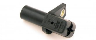
If the crankshaft sensor becomes unusable, the shape and magnitude of the output signal will be disrupted. The microcontroller polls the device for no more than 5 minutes. If there is no signal from the sensor, the control unit is switched to emergency operation mode. Then only the sensor on the crankshaft is analyzed, fuel injection is supplied to two cylinders simultaneously. Gasoline consumption increases by 10%. The main signs of a phase sensor failure:
- Significant increase in gasoline consumption.
- Deterioration of the dynamic characteristics of the car.
- Difficulty starting the engine. In the best case, it will start in 3-5 seconds.
- The Check Engine light comes on on the dashboard.
- Violation of ECU and system diagnostics.
- Errors P0343 or P0340 appear on the on-board computer.
Malfunctions of the phase sensor on the VAZ-2114 (8 valves) lead to exactly this engine behavior. It must be taken into account that malfunction can also occur if the timing belt breaks or the marks are set incorrectly. And also with excessive wear of the gears on the camshaft and crankshaft.
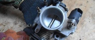
TPDZ
Electronics are responsible for fuel delivery in the VAZ-2114 car system. Without TPS, the control unit will not be able to determine the optimal time to supply gasoline. Deviations from the correct operation of the TPS lead to an increase in the amount of fuel consumed. The operation of many other car systems depends on the angle at which the remote control is located: cooling, fuel supply.
The TPS is located near the idle speed sensor. In the “fourteenth” system, the work of these two devices is closely linked.
When the TPS breaks down, the car begins to twitch in a certain position of the damper, and instability of engine operation is also noted. All VAZ-2114 8 valve sensors are interconnected in their operation, so two different devices sometimes exhibit the same symptoms of malfunction. If symptoms of a breakdown occur, it is necessary to take a comprehensive approach to checking all controllers.
How to replace it yourself
Preparatory stage:
- Open-end wrench set to “19”;
- Rags;
- Additional lighting as needed;
- New "measuring device".
Replacement algorithm:
- We install the VAZ 2114 in the perimeter of the repair area;
- We turn off the engine, open the hood;
- We provide priority safety measures: block the rear row of wheels with wheel chocks, squeeze the parking brake;
- Remove the terminals from the DTOZH, unscrew the sensor with a key;
- We replace the device with a new one, screw it in, and put on the power terminals again.
We turn the key in the ignition, activate it, and check the functionality of the equipment. Add the missing amount of antifreeze as needed.
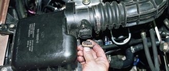
Poor contact on the connector
Driving on bad, bumpy roads leads to a violation of the reliability of fastening the contacts and plugs of the devices inside the panel. Low reliability of fastenings leads to loss of contact on the tachometer connector.
In the photo above you can see the white plug for connecting the wire block. The presence of oxides on the surface of the plug can interfere with the normal operation of the tachometer. Also, due to a poor fit of the plug, the sensor may act up and periodically display incorrect speed readings. On the surface of the board there are transistors, resistors, microcircuits, and board tracks. Failure of any of the listed elements can lead to failure of the device.
On-board computer errors
Error number P0343 very often appears after oxidation of contacts or when the electrical wiring is broken. You can independently diagnose the internal combustion engine control system using the simplest scanner that works via the K-line or the OBD-II protocol. But it is better to entrust this work to professionals who have high-quality equipment.
The most accurate check of the VAZ-2114 phase sensor (8 valves) is to install a known-good device. But keep in mind that you also need to purchase sensors for 8-valve engines. Those installed on 16-valve engines have a different design. Their output signal is different.
Brake pedal sensor
The brake pedal sensor is installed on cars to turn on the brake lights (brake lights) when the car brakes. In cars with the E-GAZ system, the brake pedal sensor is also connected to the ECU and participates in the operation of the gas pedal to distribute the engine load more evenly.
Signs of malfunction:
- Gas pedal failure;
- Jerks when moving;
- Loss of car dynamics and power;
Oxygen sensor (lambda probe)
Oxygen sensor
Installed in the exhaust pipe of the exhaust gas system. The oxygen contained in the exhaust gases creates a potential difference at the sensor output, varying from approximately 0.1 V (a lot of oxygen - a lean mixture) to 0.9 V (a little oxygen - a rich mixture). Based on a signal from the oxygen sensor, the controller adjusts the fuel supply to the injectors so that the composition of the exhaust gases is optimal for the efficient operation of the converter (oxygen sensor voltage is about 0.5 V).
For normal operation, the oxygen sensor must have a temperature of at least 360°C, so for quick warm-up after starting the engine, a heating element is built into it. The controller constantly supplies a stabilized reference voltage of 0.45 ± 0.10 V to the oxygen sensor circuit. Until the sensor warms up, the reference voltage remains unchanged. In this case, the controller controls the injection system without taking into account the voltage at the sensor. As soon as the sensor warms up, it begins to change the reference voltage. Then the controller turns off the heating of the sensor and begins to take into account the signal from the oxygen sensor.
The sensing element of the oxygen sensor is located in the exhaust gas stream. When the sensor reaches operating temperatures exceeding 360 degrees. C, it begins to generate its own emf, proportional to the oxygen content in the exhaust gases. In practice, the DC signal (with a closed feedback loop) is a rapidly changing voltage, fluctuating between 50 and 900 millivolts. The change in voltage is caused by the fact that the control system constantly changes the composition of the mixture near the stoichiometry point; the DC itself is not capable of generating any alternating voltage.
The output voltage depends on the oxygen concentration in the exhaust gases in comparison with the reference data on the oxygen content in the atmosphere coming from the sensor design element that serves to determine the atmospheric oxygen concentration. This element is a cavity connected to the atmosphere through a small hole in the metal outer casing of the sensor. When the sensor is in a cold state, it is not able to generate its own EMF, and the voltage at the DC output is equal to the reference (or close to it).
To speed up the heating of the sensor to operating temperature, it is equipped with an electric heating element. There are sensors with constant and pulsed power supply to the heating element; in the latter case, heating of the DC is controlled by the ECU. The electronic control unit constantly supplies a stable reference voltage of 450 millivolts to the sensor circuit.
An unheated sensor has a high internal resistance and does not generate its own EMF, therefore, the ECU “sees” only the specified stable reference voltage. As the sensor warms up while the engine is running, its internal resistance decreases, and it begins to generate its own voltage, which overlaps the stable reference voltage supplied by the ECU. When the ECU “sees” the changing voltage, it knows that the sensor has warmed up and its signal is ready to be used to regulate the mixture composition.
The oxygen sensor used in serial injection systems is not capable of recording changes in the mixture composition that differ markedly from 14.7:1, due to the fact that the linear portion of its characteristic is very “narrow” (see graph above in the text). Beyond these limits, the lambda probe almost does not change the voltage, that is, it does not register changes in the composition of the exhaust gas.
On VAZ cars of previous modifications (1.5 l.) in Euro-2 systems, the BOSCH 0 258 005 133 sensor was used. In Euro-3 systems, it was used as the first DC installed before the catalyst. The second DC, to control the content of harmful emissions, after the catalyst, a sensor with a “reverse” connector is installed (although there are also cars with the same ones). In new 1.5/1.6 liter cars with the Bosch M7.9.7 and January 7.2 injection system, produced since October 2004, the BOSCH sensor 0 258 006 537 is installed. See the photographs for external differences. The new DC has a ceramic heater, which allows it to significantly reduce the current it consumes and reduce the warm-up time.
To replace failed original lambda probes, Bosch produces a special series of 7 universal sensors that cover almost the entire range of standard sensors.
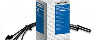
Ignition module
Ignition module
I’ll say right away: there are no simple tests that can reliably evaluate this element of the ignition system. For the reason that the spark formation process itself cannot be called simple. First, the accumulation of inductive energy in the coil, then saturation, breakdown of the spark gap, the occurrence of an arc, its combustion, and finally, damped oscillations.
Each stage has its own characteristics, characteristics and parameters, everything has its essence and weight. Changes in characteristic quantities: accumulation time, breakdown voltage, combustion voltage, arc burning time and distortion of the shape of damped oscillations provide a lot of information about the health of the coil or module.
All this is clearly visible on the monitor of a motor tester or oscilloscope, and deviations in individual cylinders are clearly visible in comparison. But according to the terms of this topic, we, like most car enthusiasts, have nothing except a control unit and a Chinese tester. Well, no need, we’ll try to get out of it, there are no hopeless situations. Actually, there are only 2 methods worth attention left: Determination of performance by the arrester and the simple replacement method. The first method is often used, but it involves having a spark gap itself, and is based on the fact that a working ignition module should be able to spark a 20mm air gap with any of its terminals. A defective module channel will not be able to do this.
Personally, I like the arrester design with an adjustable or 4-step gap of 5, 10, 15, 20 mm. By running the coil leads one by one, you can see when the weakest one gives up. I will not dwell on this in detail, the designs of arresters and descriptions of the method in the sea network. The method works, although it has certain limitations and requires some experience and skill. Therefore, I would like to focus on the second method - simple substitution, especially since it is the most accessible for car enthusiasts.
This is a really simple method, but there is one point. The ignition module is designed in such a way that it easily develops a voltage of 20 kilovolts at its terminals. When a control pulse is received from the control unit, a high-voltage discharge through explosive wires rushes to ignite the mixture compressed in the cylinder. Question. Where will the charge go if the wire is suddenly broken? (or will be completely absent - for the module this is the same thing) The discharge is looking for a way out, and unfortunately, it quickly finds it. Most often, the module pierces its own insulation with its own energy and begins to “sew” to ground along the shortest current path.
Where the insulation is weakest. The trodden path drains the charge energy onto the ground, as a result, 2 cylinders fail at once. Either 1-4 or 2-3, depending on which wire breakage triggered the insulation breakdown. The insulation may turn out to be good, then a breakdown is possible between the turns of the coil itself, again inside the module. Moreover, a breakdown can cause an interturn short circuit, or it can simply be sewn when the breakdown conditions, even on a serviceable wire, are the most severe. And these are moments of maximum load on the engine, for example, intense acceleration. Another question is which turns will close: if they are extreme, then the channel will fail.
And if they are adjacent, then the coil will lose power, and almost imperceptibly to the eye - the inductance is no longer the same. But this is for the time being. Soon, twitching, adjustments, jerks and dips, idle speed fluctuations, and other troubles will begin. These are not all types of module malfunctions, but the couple listed above indicate that its health largely depends on its operating conditions.
Therefore, in relation to our method, the question is: What will happen if, without checking the serviceability of the explosive wires, you install a known-good ignition module on your car as a replacement, kindly provided by a neighbor? (if one of the wires is broken, and the module is probably fried for this reason) Nothing may happen: your neighbor’s module may turn out to be more powerful than yours, and for the duration of a short test it will cope with the task, breaking through the gap, and you, making a mistake in diagnosis, buy a new one , which will not live long due to a broken wire.
In short, before checking the ignition module by replacing it, be sure to check the condition of the explosive wires. They can be not only the source of deterioration in driving performance, but also the cause of failure of the ignition module itself, which most often happens. Well, about the fact that it is impossible to check the serviceability of the coil and module while the engine is running by removing the explosive wires in turn from each spark plug, you cannot start or even crank the engine with the starter if at least one wire is removed from the module, you cannot use wires of dubious quality, you and so you know.
Full list of VAZ 2114 sensors: name and location
!! The injection engine installed on the fourteenth has a “brain” - an electronic engine control unit. In order to be able to regulate the operation of the power unit, the electronics must constantly monitor all changes that accompany the operation of the motor. For this, VAZ 2114 sensors are used, which we will talk about in this article.
From the material you will learn what sensors are installed on the VAZ 2114 (the information is also relevant for the VAZ 2113 and VAZ 2115), their locations, functionality and features of each device.
Sensors help the motorist (their operation can be seen on the indicators and lights of the instrument panel or BC)
Speed sensor type 2111-3843010-00
Design of the speed sensor VAZ 2114, 2113, 2115 models 2111-3843010-00
What is a speed sensor used for?
The speed sensor of a VAZ 2114, 2113, 2115 passenger car produces a pulse signal that informs the ECU about the vehicle's driving speed. DSA installed on the gearbox
When the drive wheels rotate, the speed sensor generates six pulses per meter of vehicle movement. The ECU determines the speed of the vehicle based on the pulse repetition rate.
If the DSA circuits malfunction, the controller stores its code in its memory and turns on the alarm.
Speed sensor installation location
Speed sensor connection diagram
Speed sensor terminal pinout
The pinout of the speed sensor connector terminals has the following designations:
- From the main relay - plus (“+”);
- Signal output to ECU;
- Mass - minus (“-“).
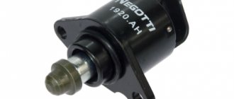
Idle air control (IAC)
Idle speed control
The idle air control (IAC) serves to maintain the set engine speed at idle by changing the amount of air supplied to the engine when the throttle is closed. The IAC is located on the throttle pipe and is an anchor-type stepper motor with two windings. When an impulse is applied to one of them, the needle takes one step forward, and to the other, a step back.
Through a worm gear, the rotational movement of the stepper motor is converted into a linear movement of the rod. The conical part of the rod is located in the air supply channel to provide control of the engine idle speed. The regulator rod extends or retracts depending on the control signal from the controller.
The idle speed control regulates the idle speed of the crankshaft by controlling the amount of air supplied bypassing the closed throttle valve. In the fully extended position (the fully extended position corresponds to “0” steps), the conical part of the rod blocks the air supply bypassing the throttle valve. When opening, the valve provides air flow proportional to the movement of the stem (number of steps) from its seat. A fully open valve position corresponds to 255 steps of stem movement. On a warm engine, the controller, by controlling the movement of the rod, maintains a constant crankshaft speed at idle, regardless of the engine condition and load changes.
In Mikas systems, a slightly different name is more often used - Additional Air Regulator (ADV). The RDV has a different design: instead of a stepper motor, a torque motor is used, which rotates the locking element at a certain angle proportional to the voltage.
Supply voltage range V: 7.5-14.2 for РХХ212-1148300-02 (Produced by KZTA) and РХХ212-1148300-01 (Produced by Pegas OJSC, Kostroma)
Testing
Turn off the ignition. Disconnect the harness connector from the regulator. Using a multimeter, check the resistance of the IAC windings. The resistance between the contacts of the idle air control system A and B, and C and D should be 40-80 Ohms. If not, replace the IAC. If yes, check the resistance between contacts B and C, A and D. The device should show infinity (open circuit). If not, replace the IAC. If so, the IAC circuit is ok.
Tips for motorists
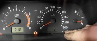
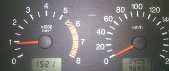
Quite often, in domestic cars equipped with ECUs, there are malfunctions in the operation of the dashboard instruments. These include the tachometer.
Many drivers, especially beginners, ask the question why the tachometer on the VAZ 2114 does not work ? There may be several reasons for this.
First, let's check the serviceability of the indicator itself; to do this, we carry out diagnostics on the instrument panel by clicking on the odometer reset, with the ignition off, turn on the ignition, as a result of which all the instrument panel arrows should rise to the maximum level and return back. If the tachometer needle does not respond during diagnostics, the pointer is most likely faulty; the remedy is to replace the instrument panel. It’s even easier to check the indicator, if the car has an on-board computer and it shows the revolutions, it means the problem is in the indicator.
Sometimes a malfunction occurs, expressed in jumps in the tachometer needle, or periodic shutdowns (works, does not work), most likely the fault here is poor contact in the wire blocks that supply and control the tachometer, or weak ground contact, on the tachometer or on ECU. It is also possible that the control circuit from the computer to the tachometer may be broken. The solution is to check the quality of the contacts on all tachometer wires. Also, the tachometer may not work together with all the other devices; the reason here is most likely in the supply of power to the panel, or rather its absence or not constant contact. The elimination method is to eliminate the cause of the lack of power - a blown fuse or an open circuit.
So, why does the tachometer on the VAZ 2114 not work? It does not work because either the device itself is faulty, or the circuits that supply and control it have a break or unauthorized contact, i.e. short circuit.
The tachometer in a car is used to indicate the number of revolutions of the engine crankshaft. Let's look at why the tachometer doesn't work and how to find and eliminate the cause of the breakdown. We will definitely dwell on the device and principle of operation, which will help to find out why the tachometer stopped working, the needle twitches or behaves inappropriately.
Video: VAZ 2114 sensors - what they are and what they do
Signaling devices called sensors are installed in order to inform the driver or some control device about changes occurring during the operation of the car or about the state of the corresponding unit or system, as well as to signal in case of failures or emergency conditions in the car. Therefore, the driver must have a good understanding of the operating principle and location of the sensors on the VAZ 2114.
- The oil level has dropped significantly;
- the oil filter is clogged;
- the oil pump has failed;
- oil pressure sensor is faulty;
- The wiring is faulty or the oil pressure has dropped due to leaks.
On an eight-valve engine, the sensor is located on the right side below the valve cover in the cylinder head. On a sixteen-valve engine - on the left end of the camshaft bearing housing.
Where is the coolant temperature sensor located on the VAZ 2114
For proper operation, ensuring the collection and transmission of optimally accurate indicators, the DTOZH must be located in direct contact with the measured medium, that is, it must be immersed in the coolant.
Let's look at a temperature sensor using the example of one of the cars in the Lada model range.
The cooling system of VAZ cars is a complex of the following parts:
- heating and cooling radiators;
- fan;
- pump;
- expansion tank;
- coolant temperature sensor.
The measuring device, located between the thermostat and the cylinder head, consists of a resistor and is connected to the control unit by two wires.
The sensor is the main signal for action
Let's start with the simplest one, which each of you is familiar with - a speed sensor. The injector carries out most of the processes for stable operation of the car, so the main part of the measuring instruments interacts with it, the speed sensor is no exception. If you have previously owned Zhiguli cars of older models, then I advise you not to apply your knowledge to this model.
Here, in addition to its main function, which is to pulse transmit the current speed to the speedometer, it helps regulate engine operation. The controller built into it regulates the air supply bypassing the throttle valve, which helps achieve a more stable idle. Therefore, if it is unstable, and fuel consumption increases, engine thrust decreases, or the speedometer does not function well, the speed sensor may be to blame. Its location has not changed - on the gearbox.
The temperature sensor is undoubtedly one of the main “alerts”, because it warns about engine overheating. I will say from my own experience, and many of you probably know, that there can be a variety of reasons. Either the pump or the pipes are leaking, the thermostat is “closed”, or maybe the fan. All this leads to an increase in the temperature of the coolant, which means overheating.
Such a measuring device will warn you about an increase in the degree of antifreeze, thereby saving the engine from sad consequences. You need to constantly monitor him. If you didn’t miss the moment and installed a broken unit, you can find it on the thermostat. This is one of those measuring instruments that has not changed compared to previous car models.
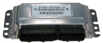
Engine management system
In general, the entire engine control system consists of two components:
By “brains” we mean an electronic control unit, or in short “ECU”, “brains”, “computer”. As they were produced, injection VAZs were equipped with different ECU models - Bosch, January, Avtel/Itelma. To learn more about the brains, the main problems, which brains were installed in certain years, the possibility of chip tuning, read the detailed article - ECU. What it is?
The brains take readings of the current state from the sensors, analyze and control the operation of the engine using the same sensors. Now let's talk about the sensors themselves that are involved in engine operation:
- Crankshaft position sensor (CPS) - serves to synchronize engine operation with the operation of the ECU, works on the principle of induction. In the event of a malfunction, the car does not start well, does not pull, ... More details in the corresponding article.
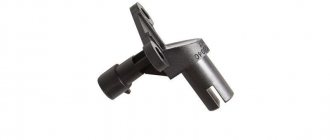
- Camshaft position sensor (CPR) - often called the “Phase sensor”. Serves to determine phased injection. It is possible to work with a faulty sensor. In details .
- Throttle position sensor (TPS), or gas pedal position sensor (if the gas pedal is electronic, installed since 2011). As for the DPZ, it is paired with the IAC. TPS determines the degree of opening of the throttle assembly. If this sensor is faulty, then there is no response to the gas pedal, the speed increases spontaneously, etc. More details in the corresponding article.
- Knock sensor (DS) - the name speaks for itself. The knock sensor detects engine vibrations (detonation) and accordingly advances the ignition angle. More details in the corresponding article.
- Coolant temperature sensor (Dtozh) - in other words, an engine temperature sensor. Installed on the thermostat, designed to control the temperature conditions of the engine. For more details on how to replace and check, see the article.
- The mass air flow sensor (MAF) is the most expensive sensor, so its failure is extremely unpleasant. Using this sensor, the ECU reads the amount of air consumed. The main malfunctions are lack of traction from the engine, problems with idling. On this site, good informative articles are devoted to this sensor, which you can read.
- Speed sensor (DS) – the speed sensor is primarily designed to measure the speed of the vehicle and is located on the gearbox. But it also has other functions - more on that.
- Oxygen concentration sensor, or simply oxygen sensor (dk) - determines the amount of oxygen in the exhaust system, regulates the mixture of fuel and air. Euro-2 has 1 sensor installed, Euro-3 has two sensors. Very often, after 60 thousand km. The second mileage sensor is disabled by software because With our gasoline it quickly breaks down. However, it can be repaired and replaced. DC is also the cause of many problems, more about this.
- Idle air control (IAC) (until 2011) or an electrically driven throttle valve (since 2011) - this sensor is responsible for stable idling. Allows air into the engine at idle speed, bypassing the TPS. Quite a capricious sensor, we replace it often. The main problem is unstable idle. Often there is a marriage. More about this.
- Electric throttle valve - (E-gas) - the essence is that it is an electronic throttle valve, which is opened not by the gas pedal cable (mechanically), but by the brains (electronically).
- Gas pedal position sensor - (E-gas) - the sensor provides readings of the gas pedal position to the computer, which in turn opens the electronic throttle valve.
As you can see, in general the number of sensors is not large, but believe me, many of them have caused many problems to car owners, so carefully study and use this material.
Electric knock sensor type 2112-3855020
Design of knock sensor type 2112-3855020 (18.3855).
The knock sensor (DS) is piezoelectric and responds to engine vibration. The DD is located on the front wall of the cylinder block. Based on the impulses of this sensor, the controller determines the moment of detonation when the engine is running and, in accordance with this, corrects the ignition timing. If the knock sensor malfunctions, the controller switches the system to backup mode.
Knock sensor device for VAZ 2114, 2113, 2115 type 2112-3855020 (18.3855)
| Item number in the picture | Explanation of the position in the figure of the knock sensor device for VAZ 2114, 2113, 2115 |
| 1 | connecting terminal |
| 2 | sleeve |
| 3 | screw |
| 4 | disc spring |
| 5 | seismic mass |
| 6 | piezoceramics |
| 7 | insulation |
| 8 | slip rings |
Connection diagram for knock sensor VAZ 2114, 2113, 2115 type 2112-3855020 (18.3855).
Analogues of the knock sensor VAZ 2114, 2113, 2115 type 2112-3855020 (18.3855):
- 21120-3855020-01;
- 21120-3855020-02;
- 21120-3855020-03.
Installation location of the knock sensor (DS)
Checking the knock sensor of VAZ 2114, 2113, 2115 type 2112-3855020 (18.3855) is performed in the following sequence:
- We connect a multimeter to the DD terminals (in voltmeter mode with a measurement limit of up to 200 mV).
- We lightly tap the knock sensor with a metal object (bolt, screwdriver), and voltage surges should appear on the voltmeter scale. A broken sensor does not respond to knocks. In this case it is changed.
Installation diagram of the knock sensor VAZ 2114, 2113, 2115 type 2112-3855020 (18.3855)
How to replace the temperature sensor?
You can replace the part yourself without resorting to the help of specialists. For ease of dismantling, it is better to choose a socket wrench or a deep socket with a knob.
Replacement is carried out on a cold engine in the following sequence:
Remove the air filter from the car. It blocks access to the sensor. After replacement, you will need to install the filter in its seat. Disconnect the negative cable from the battery. Necessary to avoid errors in the electronic control unit. Remove the protection located under the power unit. Drain the coolant from the radiator. Disconnect the wires from the sensor
When disconnecting the connector, it is important not to damage the plastic latch. It is necessary to fix the plug and prevent it from spontaneously disconnecting.
- Unscrew and replace the sensor. A 19 mm socket wrench is used. To speed up the work process, you can use a head with a ratchet.
- Reinstall the electrical wiring plug and protection.
- Fill with coolant and warm up the power unit to operating temperature.
Some car owners replace the sensor without draining the coolant. To do this, carefully unscrew the part and quickly replace it with a new one. Thus, during the replacement process, a minimum amount of coolant leaks.
A little about the oil pressure sensor
Oil is a key element in engine operation. It significantly reduces friction, which prolongs the life of many powertrain mechanisms. However, to obtain such properties, high fluid pressure is required. The oil pressure sensor will notify you if it drops, which will protect the engine from damage and save a lot of money.
You will not find any signs of malfunction here; if the pressure lamp lights up, immediately turn off the engine. Personally, because of this device, I ruined quite a few engines of the old Zhiguli 2105. Either the oil pump failed, or the oil was of poor quality, and sometimes it simply leaked out of the oil seal.
If I had a working sensor, this could have been avoided. However, it happens that everything is fine with the engine, but the electronics are acting up, then it is better to make sure of this for sure. Of course, you are interested in how to check a vital device for a car? Yes, it’s very simple, if you don’t have a new copy, then run to your neighbor for a pressure gauge.
Insert the end of the meter into the place where the hole for the sensor is located and look at its readings. We carry out the procedure with the engine running. The minimum mark for a working motor is 0.65 kgf/cm2, if so, then breathe a sigh of relief, your measuring device has simply failed.
We find and fix the problem
Signs of DMRV problems
So:
- The engine does not start;
- Unstable engine operation at idle;
- Engine idle speed is too high or too low;
- “Failures” during acceleration and poor vehicle dynamics;
- Fuel consumption is significantly exceeded.
Diagnostics
In addition to the above symptoms, a malfunction of the flow meter can be detected by the electronic control unit, namely its diagnostic system, which will issue a “CHECK” signal on the instrument panel. Unfortunately, without specialized diagnostic equipment with a 100% guarantee, it is impossible to identify a malfunction of the mass air flow sensor by reading error codes; you will have to contact a service station. Although, this is also controversial advice, since they will most likely offer you to identify the malfunction of the flow meter by replacing it with a known good device, but you can do this with your own hands without outside help. Let’s try to identify a flow meter breakdown in “field” conditions using four methods known to mankind. In general, we read carefully and remember. So, instructions:
The first method is the main one.
We disconnect the wire plug from the sensor and start the engine, the engine speed will rise to at least one and a half thousand per minute, and we’ll move off. If the car has acquired agility that is unusual for it, there is a malfunction of the sensor. Let me explain: the sensor is disabled, which means the ECU supplies the amount of gasoline according to the throttle position (emergency mode), without taking into account the signal from the flow meter.
When replacing the firmware in the ECU, no one will be able to say exactly what the idle speed setting is during emergency operation (method one). Therefore, this nuance is checked as follows: we slip a feeler gauge one millimeter thick under the throttle valve stop. After the speed rises, disconnect the sensor wire connector. The engine stalled - the firmware is to blame, or rather the idle speed adjustment in emergency mode.
The third method is the most accurate.
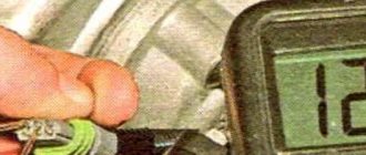
We turn the tester into DC voltage measurement mode and set the limit to two volts. We connect the probes to the yellow output wire - the plus probe and to the mass colored green wire - the minus probe, located relative to the windshield - the first and third, respectively.
Turn on the ignition, do not start the engine, take readings:
As a rule, the voltage of a working sensor is 0.996 – 1.01
Volt, but during wear it steadily increases:
- the sensor is in good condition at voltages from 1.01 to 1.02 V;
- slight wear: 1.02 – 1.03 V;
- decent mileage, will soon require replacement: 1.03 – 1.04 V;
- to be replaced at 1.04-1.05;
- It is prohibited to operate the sensor at a voltage of 1.05 Volts or higher.
Method number three
Method four, visual.
Using a curved screwdriver, remove the corrugated air duct going to the throttle assembly, and carefully inspect the internal surfaces of the air duct and sensor for the presence of condensate and oil; they should be dry and clean.
Using a ten key, unscrew the two screws and remove the sensitive element.
Checking the O-ring
As can be seen in the photo, on its front part there is a rubber sealing ring that prevents the leakage of foreign air into the intake manifold in addition to the sensor
Please note that when the integrity of the ring is destroyed, a small layer of dust forms on the sensor mesh. This is also one of the main reasons for “killing” the flow meter
In addition to the above methods, it is necessary to mention such factors as the lack of on-board power supply and unqualified maintenance (even innocent wiping of the working surfaces with a cotton swab can lead to damage to the unit). This unit is considered non-maintainable and non-repairable.
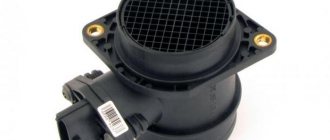
Mass air flow sensor
Mass air flow sensor
BOSH 0 280 218 004, 037, 116
To assess the condition of the sensor with acceptable accuracy, you need a few minutes, a 10-mm open-end wrench, a shaped screwdriver and a Chinese tester with a fresh battery.
1. Turn on the tester in DC voltage measurement mode and set the measurement limit to 2 Volts. We find in the sensor connector a yellow wire - output (closest to the windshield) and a green wire - ground (third from the same edge).
These are the sensor pins we need. In systems of different years, colors may change (! and the connector may already be changed), only the location of the pins remains unchanged. To assess the condition of the mass air flow sensor, it is necessary to measure the voltage between the indicated terminals with the ignition on, but NOT starting the engine!
The diameter of the tester probes allows you to penetrate through the rubber seals of the connector, along the specified wires, without disturbing their insulation, reaching the contacts themselves and without causing harm to the seals themselves. It will be useful to spray HP grease on the probes. Turn on the ignition, connect the tester, take readings. The same readings can be taken without a tester from the on-board computer display, if anyone has one. In the “voltage from sensors” parameter group. Designated Udmrv=…
2. Evaluate the results. The voltage at the output of a working sensor in the “out of the package” state is 0.996…1.01 Volts. During operation, it gradually changes and, as a rule, increases. By increasing this voltage, one can quite confidently judge the degree of “wear” of the sensor. A voltage within the above range is the best result of this test.
The following are possible options:
- 1.01…1.02 is a completely working sensor, very good.
- 1.02…1.03 is also acceptable, but the sensor is no longer young.
- 1.03…1.04 - most of the resource is already behind, you can plan for a quick replacement.
- 1.04…1.05 - clearly a tired sensor, it has already served its purpose. If your budget allows, feel free to change it.
- 1.05...and higher are a source of problems, it’s high time to replace them.
3. If, according to the assessment results, the sensor has deviations, and in general, even if it does not, but since we have already gotten around to it, we carry out a visual inspection. Using a figured screwdriver, unscrew the clamp of the rubber corrugation-air intake at the sensor outlet, pull off the corrugation from it, and carefully inspect the internal surfaces of both the sensor itself and the corrugation.
Attention! These surfaces must be dry and clean like... a baby's, without traces of condensation and oil! Their contact with the sensitive element of the sensor is the most common cause of its premature death. This happens both because the oil level in the crankcase is too high, and because the oil sump of the crankcase ventilation system is clogged, the outcome is usually the same. If this phenomenon occurs in the intake tract, replacing the sensor is contraindicated! Until the causes are eliminated, so that there is no excruciating pain later for wasted money.
4. Using a 10mm wrench, unscrew the 2 screws securing the sensor to the air filter housing and remove the sensor. On the front of it, on the inlet edge, which has just been removed from the filter, there must, by law, be a rubber sealing ring. It serves one purpose - to prevent the suction of unfiltered air into the intake tract through the sensor and further into the piston group.
As a rule, the ring is not in place - it is stuck in the air filter housing and is avoiding its direct responsibilities. This can be confirmed by a thin layer of dust on the input grid of the sensor itself. We run our finger over it and draw conclusions. If the rubber band was in place, we draw conclusions about its elasticity or the quality of the air filter. Another reason that kills the sensitive element!
We take out the ring and restore the legality of the assembly. The ring has a sealing belt-skirt on the inner surface. When assembling, make sure that it does not curl up, which is also a source of dust. I understand about the air filter. The assembly, with the exception of the sealing rubber, is not tricky - first put it on the sensor, check the sealing skirt, then put it all together into the filter housing. Then the sensor enters the filter housing with noticeable force. We tighten the screws.
The described method is not exhaustive and absolute, but within the framework of an amateur express check it is quite worthy of attention. A more accurate method is only possible if you have professional equipment.
Location of sensors on the VAZ 2114
Signaling devices called sensors are installed in order to inform the driver or some control device about changes occurring during the operation of the car or about the state of the corresponding unit or system, as well as to signal in case of failures or emergency conditions in the car. Therefore, the driver must have a good understanding of the operating principle and location of the sensors on the VAZ 2114.
Oil pressure gauge
An important device that signals low oil pressure in the engine. When this happens, it indicates problems in the propulsion system
The most serious consequence of ignoring this signal may be a major overhaul or complete replacement of the engine. The emergency oil pressure light associated with the sensor lights up in several cases:
- The oil level has dropped significantly;
- the oil filter is clogged;
- the oil pump has failed;
- oil pressure sensor is faulty;
- The wiring is faulty or the oil pressure has dropped due to leaks.
On an eight-valve engine, the sensor is located on the right side below the valve cover in the cylinder head. On a sixteen-valve engine - on the left end of the camshaft bearing housing.
The design of the DDM is extremely simple, and its price is low, therefore, if it fails, it is more economical to buy a new one than to repair it.
- Coolant temperature meter. It is also called the engine temperature sensor. The question is often asked on forums: where is the VAZ 2114 engine temperature sensor located? It is installed on the inlet pipe of the cylinder head cooling jacket. Checking its performance is quite simple. It is enough to connect an ohmmeter to it and lower the DTOZH into a vessel with liquid. When heating it, you need to monitor the temperature and the change in resistance due to its increase. If the required schedule is met, the device is considered operational.
- The coolant level sensor is located in the antifreeze tank. It is screwed on like an ordinary plastic cap, then the electrical connector is connected.
- The brake fluid level sensor is a float-type device, installed in the brake fluid reservoir.
- The idle speed sensor, or IAC, is installed on the throttle body next to the throttle valve.
- Mass air flow sensor - located on the air filter housing near the large intake pipe.
- Throttle position sensor - located on the throttle body.
- Crankshaft position sensor. It is also called a synchronization sensor, due to the fact that, according to its readings, the controller synchronizes its work with the injection system. Installed next to the generator drive pulley.
- Camshaft position sensor or timing sensor - located on the air filter side next to the cylinder head cover. Depending on the position of the camshaft, it sends an impulse to the computer and injection occurs just before the valve opens. The fuel is thrown in simultaneously with a portion of air, mixes well and high-quality detonation occurs.
- Oxygen sensor or lambda probe. It is located in the intake manifold of the exhaust system in front of the resonator. Sends a signal to the electronic on-board system about the level of oxygen concentration in the exhaust gases.
- Knock sensor - installed between the second and third cylinders on the power unit block on the fan side. Its readings, through the controller, affect the ignition timing.
These are all the main sensors on the VAZ 2114 engine. However, there are other sensors that provide readings on the VAZ 2114 indicating its performance or the state of the environment or road surface.
- Fuel level meter - located in the intake chamber of the fuel tank. The VAZ 2114 is equipped with a DUT-1-03 type sensor.
- A speed measuring device is located at the gearbox and transmits data about the current speed of the car to the speedometer. It is also connected to a controller, which, receiving its impulses, regulates the operation of the IAC or throttle valve, depending on the position of the gas pedal and the engine speed.
- Rough road clamp (sensor)—it is mounted under the hood on the body in the area of the right mudguard cup. It reports changes in body vibrations to the controller; if the signal level is exceeded, the electronics turns off the misfire diagnostics.
- The outside temperature sensor (that is, the surrounding atmosphere) is its standard location on the VAZ 2114 - in the center behind the front bumper.
Crankshaft sensor (CPCV)
The crankshaft sensor (DPKV) 2114, 2113, 2115 is designed to create pulses by which the controller synchronizes its operation with the clock cycles of the motor. Hence this sensor is called a synchronization sensor. The operation of the crankshaft sensor is based on the principle of induction - when the crankshaft pulley teeth pass the sensor core, AC voltage pulses are generated in the sensor circuit.
The frequency of pulse occurrence is equal to the crankshaft rotation speed. The crankshaft pulley teeth are spaced around the circumference at 6° intervals. 2 of them are spaced from each other at an angular distance of 18°. This was done to create reference signals in the VAZ 2114, 2113, 2115 crankshaft sensor circuit - reporting points, relative to which the controller determines the position of the crankshaft - top dead centers in the 1/4th and 2nd/3rd cylinders.
It is impossible to operate the engine with a broken DPKV. This sensor cannot be repaired. When it breaks, it changes.
Designation of the crankshaft position sensor (CPS):
- According to VAZ classification - 2112-3847010;
- According to the manufacturer's classification - 191.3847.
Crankshaft sensor design for VAZ 2114, 2113, 2115:
| Position number on the diagram | Explanation of the position on the diagram of the crankshaft sensor device for VAZ 2114, 2113, 2115 |
| 1 | Crankshaft sensor VAZ 2114, 2113, 2115 |
| 2 | Master disk |
| A | Permanent magnet |
| B | Magnetic core |
| IN | Winding |
| G | Start of counting |
Crankshaft sensor connection diagram:
Installation location of the crankshaft sensor (DPKV) VAZ 2114, 2113, 2115:
More detailed information about the crankshaft sensor VAZ 2114, 2113, 2115 is available on the page of this site Crankshaft sensor 2114, 2113, 2115 8 valves
GENERAL INFORMATION
Most of the units we are considering are located in the engine compartment. We present to your attention a diagram of the arrangement of sensors on the VAZ 2114 engine:
The location of the sensors must be known to the responsible motorist
- Camshaft position (phase sensor);
- Coolant temperature;
- Detonation;
- Oil pressure;
- Oxygen sensor (lambda probe);
- Kneeshaft position;
- Speed;
- Idle move;
- Mass air flow;
- Fuel level;
- Gasoline level;
- Antifreeze level;
- Throttle Positions
Now let's look at the sensors and their location in more detail.
CRANKSHAFT POSITION SENSOR
DCP is a device that supplies the computer with information about the position of the crankshaft. The correct functioning of the fuel mixture supply and ignition systems, as well as the injectors of the injection engine, depends on the operation of this unit.
This device is often called a synchronization sensor, since the ECU, based on information received from the DCPV, determines the moment of fuel injection into the engine cylinders. If the DCPV breaks down, incorrect information will be supplied to the brains of the fourteenth and the engine will lose its performance, since there will be malfunctions in the fuel supply system and the injectors will not be able to function normally.
On the fourteenth, inductive type DCPVs are installed, the approximate cost of a new device is 150 - 200 rubles. The DCPV is located near the alternator belt, near the camshaft.
CAMSHAFT POSITION SENSOR
DPR is often called a phase sensor. This device is available on all fourteen cars with 16-valve engines, and on VAZ-2114 with 8-valve engines with phased injection of the fuel mixture.
The DPR transmits data about the current operating cycle of the power unit to the ECU:
- Which valve is open?
- What valve timing is being implemented at the moment.
Based on the information received, the ECU determines the timing of fuel injection so that gasoline is supplied just before the intake valve opens.
The device is located on the engine, near the cylinder head, not far from the air filter.
Phase sensor for VAZ 2114
THROTTLE POSITION SENSOR
TPS is one of the key devices, the correct functioning of which depends on the operation of the fuel system. As the name implies, TPS transmits information to the brains of the fourteenth about at what angle the throttle valve is placed at a particular moment in time
One of the main characteristics of the TPS is the signal frequency, based on the change in which the engine control unit determines the degree of pressure on the gas pedal, which allows the brain to select the optimal engine cooling mode and the amount of fuel supplied.
TPS is part of the throttle assembly. It is located on the throttle body, next to the idle speed sensor.
KNOCK SENSOR
A properly functioning DD is the key to the normal functioning of the fourteenth engine. If it breaks down, the engine will run rough and gas mileage will increase.
The DD reacts to engine vibrations, information about which is transmitted to the ECU, which allows the ECU to select the correct ignition timing (the moment of ignition of gasoline in the cylinder).
The device is mounted on the engine cylinder block next to the fan, between the 2nd and 3rd cylinders.
COOLANT TEMPERATURE SENSOR
DTOZH (also referred to as the VAZ 2114 engine temperature sensor) is located at the place where the inlet pipe is located on the body of the cylinder cooling system, to which the antifreeze supply pipe is connected.
Throttle position sensor (TPS) model 2112-1148200
Design of the throttle position sensor VAZ 2114, 2113, 2115 model 2112-1148200
The throttle position sensor (TPS) of VAZ 2114, 2113, 2115 model 2112-1148200 is mounted on the side of the throttle pipe opposite the air shutter control lever. TPS is a potentiometric type resistor, one of the contacts of which receives a reference voltage of 5 V from the ECU, and the second one receives a negative voltage from the controller. From the terminal connected to the moving contact of the potentiometer, the output pulse of the TPS is sent to the controller. When the accelerator pedal moves, the throttle valve shaft transmits its rotational motion to the throttle valve sensor, causing a change in the voltage of the TPS output signal. When the throttle valve is closed, the output pulse of the TPS VAZ 2114, 2113, 2115 must be within 0.3...0.7 V. When the air valve is opened, the output signal increases, and when the throttle valve is opened by 76...81% according to the diagnostic device, the output voltage must be 4.05...4.75 V. By measuring the output voltage of the TPS pulse, the ECU determines the current position of the air gate.
Information about the location of the throttle valve is needed by the controller to calculate the ignition timing, the duration of injection pulses and the IAC state. By monitoring changes in voltage, the ECU determines whether the throttle valve is opening or closing. The ECU perceives the rapidly increasing voltage of the TPS pulse as evidence of a growing need for gasoline and the need to increase the duration of injection pulses. The throttle sensor is not adjustable. The controller uses the lowest TPS signal voltage at idle as a reference point (0% throttle opening). Breakage or weakening of the VAZ 2114, 2113, 2115 TPS fasteners can cause poor idling, because The ECU will not receive an impulse to move the air valve.
When a malfunction occurs in the TPS circuits, the controller stores its code in its memory and connects the alarm. When this happens, the ECU calculates the throttle position parameters based on crankshaft speed and air mass flow.
Connection diagram for the throttle position sensor (TPS) VAZ 2114, 2113, 2115.
Pinout of the throttle position sensor (TPS) VAZ 2114, 2113, 2115:
Location of TPS (throttle position sensor)
Analogues of the throttle position sensor model 21120-1148200-00:
- 21120-1148200-31.
Replacing the throttle position sensor (TPS) of VAZ 2114, 2113, 2115 is performed in the following sequence:
- Disconnect the minus contact from the battery;
- Remove the clamp from the TPS terminal block
- Disconnect the terminal block of the throttle sensor VAZ 2114, 2113, 2115
- Use a Phillips screwdriver to unscrew the 2 screws that secure the throttle position sensor.
- We remove the TPS together with the foam ring installed between the sensor and the throttle assembly
- We put a foam rubber ring on the throttle shaft;
- We place the TPS on the throttle valve drive axis so that its contacts are oriented towards the partition of the engine compartment;
- We slightly rotate the sensor relative to the throttle shaft until the holes for its mounting screws coincide with the threaded holes in the throttle body;
- Tighten the screws securing the throttle position sensor;
- Open the throttle valve by turning its drive sector all the way. If this cannot be done, then the TPS is installed incorrectly. You should remove the sensor from the throttle shaft and reinstall it relative to the axis at 90o;
- After making sure that the throttle sensor is mounted correctly, connect the wiring harness terminal block to it.
Checking the throttle position sensor of VAZ 2114, 2113, 2115. This procedure is performed using a tester in voltmeter mode or a diagnostic device.
Checking the TPS using a voltmeter is performed in the following sequence:
- Disconnect the contact block from the throttle sensor;
- We turn the tester into voltmeter mode to measure DC voltage;
- We connect the negative contact of the voltmeter to the engine ground;
- We connect the positive probe of the voltmeter to contact “A” of the TPS terminal block. The contact designations are marked on the terminal block.
- Turn on the ignition;
- We measure the voltage at terminal “A”. It should be around 5V. If the voltage does not reach the contact or is less than 5V, then the circuit or ECU is faulty;
- We connect the terminal block to the throttle sensor;
- We stick the needle into the output contact of the TPS terminal block;
- We measure the voltage of voltmeters between the output contact of the TPS and the engine ground. With the ignition on and the throttle valve closed, the sensor output voltage should be 0.3...0.7 V. After this, slowly open the throttle valve - the sensor output voltage should increase to 4.1...5 V. If it is outside the ranges - Replace the throttle position sensor.
Air sensor VAZ-2114
Modern environmental requirements for internal combustion engines are increased. That is why, in all modes of its operation, the established ratio of air to fuel in the air-fuel mixture must be maintained.
Only if these conditions are met will the catalytic converter completely remove harmful substances in the exhaust gases.
To maintain the stoichiometric ratio of the various components present in the fuel-air mixture, reliably accurate information on the amount of air consumed is required.
The air flow sensor installed on the VAZ-2114 is designed to collect air flow data. The measure of intake air flow can be calculated both in volume and in mass.
Today there are two types of air flow sensor: thermal and mechanical.
With the mechanical method, the incoming air is measured, which is proportional to the movement of the damper. The basis of the thermal method is to measure the mass of incoming air, which directly depends on the temperature of the sensitive element for a given period of time. The car's air flow sensor is installed between the throttle valve and the air filter in the intake system.
Mass air flow sensor model 21083-1130010-01
Design of mass air flow sensor (MAF) type 21083-1130010-01
The engine control system uses a hot-wire mass air flow sensor (MAF). It is located between the air filter and the intake pipe hose.
The mass air flow sensor pulse is a direct current voltage, the size of which depends on the volume and direction of air movement passing through the mass air flow sensor. With a forward air flow, the voltage of the sensor output signal changes in the range of 1...5 V. With a reverse air flow, the voltage of the sensor output pulse changes in the range of 0...1 V. The diagnostic device reads the sensor readings as air flow in kilograms per hour.
When a breakdown of the mass air flow sensor circuit occurs, the ECU stores its code in its memory and turns on the warning light. In this case, the ECU calculates the mass air flow value based on the crankshaft speed and throttle position.
Connection diagram for mass air flow sensor (MAF) VAZ 2114, 2113, 2115 type 21083-1130010
Installation location of the mass air flow sensor (MAF)
Detailed information about the mass air flow sensor is located on the page of this site called DMRV 2114, 2113, 2115 8 valves
Built-in air temperature sensor in the mass air flow sensor
The air temperature sensor is built into the air flow sensor. The sensitive element is a thermistor (a resistor that changes resistance depending on temperature) mounted in the air flow. The output pulse of the DTV ECU connected to the con is a direct current voltage in the range 0...5 V, the size of which depends on the temperature of the air passing through the sensor.
When a malfunction occurs in the DTV circuit, the controller stores its code in its memory and turns on the alarm. In this case, the ECU replaces the sensor readings with a fixed air temperature value of 33 oC.
| Table of dependence of DTV resistance on intake air temperature (±10%) | |
| Air temperature, oС | Resistance, kOhm |
| — 40 | 39,2 |
| — 30 | 23 |
| — 20 | 13,9 |
| — 10 | 8,6 |
| 0 | 5,5 |
| + 10 | 3,6 |
| + 20 | 2,4 |
| + 30 | 1,7 |
| + 40 | 1,2 |
| + 50 | 0,84 |
| + 60 | 0,6 |
| + 70 | 0,45 |
| + 80 | 0,34 |
| + 90 | 0,26 |
| + 100 | 0,2 |
| + 110 | 0,16 |
| + 120 | 0,13 |
Problems and solutions
There are a lot of reasons for unstable idle, and they apply to both carburetor and injection engines and even diesel engines, both to the old type design and to the new E-gas pedal, which AvtoVAZ is so proud of. Let's start with the problems that occur in carburetor-type engines:
- The fuel-air mixture has become lean. To fix the problem, you just need to make an adjustment to the level of eight hundred revolutions.
- Unstable running can also occur due to wear on the carburetor valve. In this case, the engine operates exclusively with the choke mode extended. To fix the problem, you need to replace the defective part with a new one.
- It also happens that the system channels become dirty. Then the fuel does not receive the required portion of air and leads to failure. Here you just need to clean the channels.
In the injection type of engine, there are no fewer reasons for failure.
- The first thing you can check is air leaks. Be sure to check the connection between the intake manifold and the cylinders to see if the gaskets are worn out. There are rubber plugs on the same manifold; if they are cracked, it is better to replace them. You can check all this by buying carburetor cleaner or any other flammable item in the store, start the car and spray all the joints, if there is a leak, the car will start to twitch, look in that place.
- They can cause gaps in speed and malfunctions in the IAC sensor (idle air control), it is often enough to remove it and clean it or inspect it for damage and replace it if necessary.
But problems with electronic equipment, in particular the famous E-gas, are much more complicated. Here it is observed:
- regulator failure (IAC);
- DMRV sensor failure;
- failure of the EGR valve (adsorber);
- damage to wires.
Device failure
After checking the connectors, ground and integrity of the wiring, you should examine the condition of the device. Because The design of the speed arrow includes a gear motor; its failure can also cause a malfunction.
Finding a separate part for installation in an old panel is difficult, because... This motor rarely fails. Purchasing a new panel assembly is expensive. The cost of a new spare part is about 300-500 rubles, but it is often difficult to find this element in stock. To restore its normal operation, you can clean the motor from dirt and try to fix the mechanical failure.