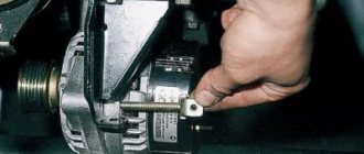
Stable and correct operation of the car’s electronics largely depends on the serviceability of the generator. It provides power to all devices and also helps start the engine. In this regard, it is important to monitor its serviceability, and if necessary, know how to check a car generator with a multimeter.
This element is directly connected to the battery, which also often causes problems. And if it is necessary to connect new devices and various devices to the standard on-board network, you should check the serviceability of the generator, since it is the source of the standard current. In other words, this is one of those parts that needs to be checked regularly.
Beginning of work
To start checking, no special preparations are required. You just need to prepare the multimeter itself. It is also advisable to check the generator - inspect the generator stator, diode bridge, voltage regulator, etc. This makes it possible to identify faults at an early stage. In addition, an external inspection of other elements of the vehicle's electrical circuit should be carried out. No further work may be required.
So, the verification includes several stages:
- Inspection of the relay regulator.
- Checking the diode bridge.
- Checking the stator.
- Checking the rotor.
Relay regulator
Relay regulator from Priora and 2112
The relay regulator maintains the optimal voltage value in the standard electrical circuit. In fact, it is precisely this that prevents the voltage from increasing to critical values. To carry out the test, start the engine, connect the multimeter and set the “voltage measurement” value.
After this, it is necessary to measure the power supply of the on-board network directly at the battery terminals or at the contacts of the generator itself. The values should be between 14–14.2 V.
Diode bridge
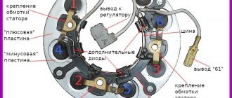
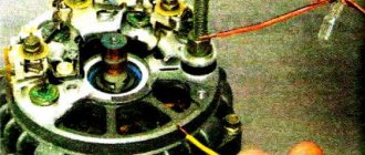
We call the diode bridge
When the multimeter probes are positioned as in the following photos, the resistance should be infinite; if the probes are swapped, it should be within 700 Ohms.
Procedure for checking negative diodes
Checking the positive diodes
Now the auxiliary diodes
- Procedure for checking negative diodes
- Checking the positive diodes
- Now the auxiliary diodes
Generator rotor
The rotor is a rod made of metal with an excitation winding. If you look at one of its ends, you can see special contact rings with sliding brushes.
First of all, it is necessary to remove the rod and conduct an external inspection of the winding, as well as the bearings. In some cases, the problem is damage. If everything is in order, then you should proceed to checking with a multimeter.
The device should be set to “Resistance measurement” mode. It should be checked between the slip rings. This value should not be too large - this indicates the serviceability and integrity of the winding.
Note! It is quite difficult to carry out detailed diagnostics of the rotor on your own, so if you suspect any problems, you should contact a car repair shop.
Generator stator
The stator looks like a small cylinder with a winding inside it. Before checking, the stator itself must be disconnected from the diode bridge. First of all, you should carefully inspect the stator, as well as its individual elements, for any damage. Particular attention should be paid to signs of possible burning.
Next, you can check with a multimeter by setting the “Resistance measurement” mode. With its help, winding breakdowns are detected. To do this, one contact should be connected to the body, and the other to the winding terminal.
Note! In this case, the resistance must be very high; in fact, it tends to infinite values. If the readings are less than 50 kOhm, then this most likely indicates a malfunction of the stator and the entire generator.
General Tips
Before starting the test, you should always find out in advance which generator set is on the car. For example, depending on the model of the machine, the relay regulator can support different values in the range from 13.6–14.2 V. You need to know this in advance, since in the end all this affects the final result of the test.
Otherwise, there are no particular difficulties, so it is quite possible to identify malfunctions or other problems that happen from time to time with the generator and other elements of the on-board electrical circuit on your own.
Source: https://www.vazzz.ru/kak-prozvonit-generator-vaz-2110-multimetrom/
Trouble-shooting
There are two main options for solving the problem. The first is accurate diagnostics on the bench: after detecting signs of burnt-out diodes, a check is carried out and it is determined which elements have failed. After this, the faulty diodes are soldered off, and new ones are soldered in their place. It is very important to take exactly the same brand; any analogues will not last long.
It is much easier to change the assembly, it is faster and of better quality, since you can be sure that the spare part will last for some time. The price of the part is low, for example, on a VAZ 2110 it is about 650 rubles. Replacement is not difficult and can be done independently.
Identifying a faulty diode bridge and replacing it is not difficult for any car enthusiast with a minimum set of tools. If the check shows a breakdown, it is best to remove the generator and carry out repairs. The process is simple and takes no more than an hour.
Checking the VAZ 2110 generator with a multimeter
It is impossible to imagine a VAZ 2110 car without electrical appliances. Lighting, battery charging, on-board controllers, and electric motors consume electricity generated by the generator. Monitoring the condition of electrical equipment increases the service life of devices and wiring. The article contains practical advice on various ways to check a VAZ 2110 generator with a multimeter.
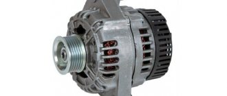
VAZ cars are equipped with three-phase synchronous alternating current generator devices equipped with a diode rectifier and an electronic voltage relay regulator. The V-belt transmits torque from the engine pulley to the electric machine pulley. A constant excitation voltage is supplied to the slip rings with graphite brushes and is removed from the B+ terminal.
Main components of the device:
- front and rear covers with bearings;
- stator;
- rotor;
- diode rectifier bridge;
- output voltage regulator relay;
- brush holder.
Possible faults
Complete or partial jamming of bearings. Symptoms – belt break, incomplete charge of the battery (detected by a warning lamp on the instrument panel, a measuring tester, a load fork).
Checked:
- visually with the engine running;
- Turn off the engine, remove the belt, and turn the pulley by hand. Failure to rotate freely and evenly indicates the need for repair.
Malfunctions of the stator, rotor. The device is operated in an aggressive environment; dirt and caustic liquids may enter. The insulation of the winding wires is destroyed, causing interturn short circuits to the housing.
Signs – cessation of generation, dim lamp light, indicator light is on, extraneous sounds in the generator. It is checked with the VAZ 2110 generator removed using a multimeter.
The graphite brushes have worn out. Symptoms are the same as in the previous paragraph. Checking and replacement are carried out without removing the equipment. Takes 10 – 15 minutes.
The voltage regulator is not working. Signs:
- Battery charging is insufficient, mains voltage is too low, light bulbs are dim;
- overcharging of the battery, bright light, high voltage, drips of dried electrolyte.
It is tested by measuring the voltage at the battery terminals.
Checking the VAZ 2110 generator with a multimeter on a car
To check the electrical parameters of the car, you will need a combination meter that allows you to set the switch:
- constant voltage within 0 - 30 volts;
- resistance 0 – 5 Ohm, 0 – 200 Ohm, 0 – 2 MOhm.
Step-by-step diagnostic instructions
- Set the switch to DC voltage measurement mode. Use the red probe to touch the positive contacts.
- Measure the battery voltage with the ignition off. The norm is in the range of 12.5 - 12.7 volts.
- Start the engine. Idle speed. Devices and lights are turned off. A value of 13.8 - 14.5 volts is considered normal.
- Turn on power consumers (low beam, fog lights, multimedia devices).
If the equipment is in good working order, the tester will show 13.7 - 14 volts. An on-board voltage below 13V indicates a malfunction of the generator unit. Pressing the gas pedal to increase engine speed should not raise the voltage by more than half a volt. A reading above 15 volts indicates a malfunction of the relay regulator.
Checking the generator components on the table with a multimeter
Once a malfunction is suspected, the device is dismantled and diagnosed.
- Place the car on a viewing hole or lift the front part with a jack, and place a safety support.
- Loosen the fastening, disconnect the negative terminal from the battery.
- Disconnect the wires from the generator.
- Unscrew the adjusting and mounting bolts.
- Remove the belt.
- Remove the device and disassemble.
- Checking the diode bridge of the VAZ 2110 generator with a multimeter is performed in resistance measurement mode, range 0 - 2 MOhm. Silicon diodes used in the rectifier circuit, passing a current of up to 80A during operation, heat up. The cooling radiator is a metal mounting ring. Structurally, two types of rectifiers are produced: with an anode and a cathode on the body. Motorists call parts of the first type positive, the second - negative. A working diode in the forward direction shows a resistance of 0 Ohm, in the reverse direction - about 600 kOhm. A zero value in both directions means a breakdown of the device, a high value means a break. Additional diodes are checked in the same way.
- The rotor field windings are tested with a tester at the switch position of 0 - 5 Ohm. Test leads are connected to slip rings. The resistance value ranges from 1.8 – 5 Ohms. Less is a short circuit, more is a gap.
- The stator windings are tested in the range 0 - 200 Ohm. Alternately touching the terminals of two serviceable windings will show units of Ohms on the instrument indicator; the absence of readings means a malfunction.
- The integrity of the winding insulation is measured by touching one probe to the winding contact, the other to the housing. An infinitely large value indicates normality.
Selection of diodes for the rectifier bridge
The main thing they look at when choosing a diode is power. It depends on the highest rated current generated by the generator. The higher the generator power, the more powerful the diodes. Diodes for the rectifier bridge are conventionally divided into categories: low power diodes, current 300 mA;
medium power diodes, current 300mA – 10 A;
high power diodes above 10 A.
Diodes are divided according to the type of material used, these are germanium and silicon. Most manufacturers prefer silicon diodes. The main reasons for choosing silicon diodes:
· low reverse current;
· high permissible reverse voltage up to 1500 V;
·operability of silicon diodes from -60 to +150оС
Germanium diodes have a low reverse voltage value of up to 400V. They operate in the temperature range from -60 to +85°C.
For example, to replace diodes for a Bosch generator with a 140A for a Touring Custom car. For such a generator you need 50A diodes, for example, Cargo 50A 138634 and Cargo 138635, for a 140A generator you will need 12 pieces, for an 80A generator 6 pieces.
How to test a generator with a multimeter
The malfunction of the car generator is classified as critical, in which further operation of the vehicle is not allowed. You can use a multimeter to check the functionality of the generator.
Signs of generator failure
Signs of abnormal operation of a car generator may include:
- no “battery” indication on the dashboard when the ignition is turned on;
- the “battery” light glows after starting the engine;
- periodic blinking of the “battery” signal indicator while driving;
- the smell of burnt electrical wiring in the generator area;
- failure to start the engine after parking.
Lack of battery charge with a faulty generator leads to problems with starting the engine. More dangerous is a malfunction associated with exceeding the current and voltage of the car battery charge.
Many car enthusiasts use a donor battery to start the engine, after which they disconnect the battery terminals to switch to charging their own battery.
If the generator is faulty, the voltage in the on-board network may be more than 17 volts, which leads to breakdown of the protective zener diodes in the engine control unit. In this case, expensive repairs to the engine control unit are required.
Causes and possible consequences of the malfunction
The generator may not work for the following reasons:
- malfunction of the voltage regulator (“pills”, “chocolates” in the slang of car enthusiasts);
- wear (destruction) of brushes;
- short circuit of the exciting winding (rotor);
- breakdown of diodes (located in the horseshoe);
- wear of bearings and bushings.
A faulty voltage regulator usually results in a lack of battery charge. In this case, the “battery” indicator light appears on the dashboard. The engine continues to run until the battery is discharged to approximately 8 - 9 volts.
During daylight hours, the battery charge may be enough for 30-50 kilometers, provided that the battery was well charged at the time the malfunction occurred.
If the output stages of the voltage regulator breakdown, a malfunction may occur due to an increase in the generator output voltage to 17 - 20 Volts. This recharges the battery. The consequence of overcharging is the process of boiling of the electrolyte. If signs of corrosion appear under the hood in the battery area, it is necessary to check the generator.
A breakdown of the diode bridge can occur when the battery is accidentally reversed (installing the terminals in the wrong polarity). Typically, diodes are punched in pairs in one arm. A faulty diode has a resistance close to zero. In this case, the stator winding of the generator operates in short circuit mode and becomes very hot.
After a few minutes of engine operation, the windings overheat, and a smell of burnt electrical wiring appears under the hood of the car. To avoid fire, the engine must be turned off and the generator checked.
Wear of the brushes leads to gradual failure of the generator. First, while driving, the charge indicator light on the dashboard begins to blink, then it begins to glow constantly. In many generator models, the brushes are changed together with the voltage regulator.
A short circuit in the generator windings can lead to a significant change in output parameters and overheating of the device.
Initial check sequence
An initial performance check can be performed without dismantling the generator. To do this, set the multimeter switch to the “constant voltage 20V” mode.
Next, connect the black probe to the negative terminal of the battery, the red one to the positive terminal. After this, you need to start the engine and let it reach a stable idle speed.
Multimeter readings ranging from 13.5 to 14.5 Volts are considered normal.
If the multimeter shows a value less than 12.8 Volts, the charging process either does not occur at all, or the charging current is extremely small. The generator is operating in abnormal mode. When the voltage is more than 14.8 Volts, the battery is overcharged. This can lead to boiling of the electrolyte, an increase in acid concentration, and destruction of the battery plates.
To check the voltage at the generator output, you need to turn on the car lamp in the open circuit from terminal 30 on the generator (the point of contact with the thick wire leading to the positive terminal of the battery or starter).
When checking, you should evaluate the degree of tension of the generator belt. Using a simplified method, this can be done by pressing on the belt with your finger.
The amount of deflection should be within 0.5 - 1 centimeter. At the same time, check the degree of belt wear. To determine the reasons for abnormal operation of the generator and perform repair work, dismantling the generator is required.
Checking generator components
The test begins with monitoring the functionality of the voltage regulator. To do this, the regulator is removed from the generator and a simple electrical circuit is created.
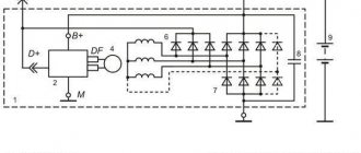
Any car interior light bulb can be used as an incandescent lamp. If voltage regulator 3 is working properly, lamp 6 should not glow at full power.
When connected in parallel with the lamp (brushes) of a multimeter, its readings should be from 5.0 to 10.0 Volts. If the multimeter readings fall outside these limits, the regulator must be changed.
The design of some generator models allows for the possibility of replacing the regulator without dismantling the device.
Next, check the exciting winding of the generator for breakdown. To do this, set the multimeter to resistance measurement mode at a limit of 200 kiloOhms. The probes are connected: black - to the commutator lamella, red - to the metal part of the armature. The resistance should be more than 100 kiloohms or higher than the upper limit of measurement, as shown in the photo.
Checking the stator begins with checking the windings for breakdown. To do this, the red probe of the multimeter is connected to the metal part of the stator, the black probe is connected in series to the windings.
The resistance must be above the upper measurement limit. Then the resistance between the winding contacts is measured. They should differ by no more than 5%. The measurement limit of the multimeter is set to 200 ohms.
If the winding has an electrical breakdown, a short circuit of the turns or a break, it must be replaced. There are workshops that rewind stators and rotors.
To check the health of the diode bridge, the multimeter measurement mode is switched to the “diode” test. Then the diodes (their number on a horseshoe is usually 9) are sequentially “ringed” in forward and reverse connection. In the forward direction (black probe to the cathode) the resistance is 550 - 700 Ohms, when switched in reverse it is greater than the maximum measurement limit.
When the diodes breakdown, the resistance in all directions will be practically zero. This diode should be changed. The difficulty of replacing a diode lies in the fact that the diodes in generators are not soldered, but spot welded to ensure reliable contact at different temperature conditions.
Battery overcharge
However, often it is not “undercharging” and “overcharging”. The electrolyte from the battery boils away and the battery also fails; there is nothing good about this either.
The first sign will be white streaks on the top of the battery, which means the electrolyte simply boils and evaporates. That is, the battery is charged, but the generator still “craps” charging it. The relay regulator has most likely failed here.
The check here is also elementary - you need to connect a multimeter or tester (whatever they call it) with the car running, and look at the charge. If it greatly exceeds 14.5 - 14.8 V, but is within the range of 15 - 15.2 V, it means that it is overcharging. We urgently change the relay-regulator, otherwise you will constantly boil your battery, ALSO NOTHING GOOD. It’s trivial that the plates may crumble.
Now let's watch the video version.
That’s all, he told me, exactly the methods without removing it from the car, and of course give it to a good auto electrician for repairs.
This is where I end, sincerely yours, AUTOBLOGGER.
(
36 votes, average: 4.42 out of 5)
Similar news
Engine chip tuning. Advantages and disadvantages. Is it worth doing at all? .
Generator overrunning clutch. What is it and what is it for? Important.
Why does the alternator belt whistle? When cold or under load. .
How to test a generator with a multimeter
What to do if there is no light in the house? A current generator can help solve the problem. But if this equipment also fails, checking the generator with a multimeter will help determine the malfunction. Regardless of the type and brand, with the help of this device, once you find out the cause of the malfunction, you can carry out simple repairs yourself.
There are many types of generators, from large and powerful industrial devices to small automotive devices. But the testing algorithm using the tester is the same for any generator.
What components and parts are checked using a multimeter?
This operation involves diagnosing the electrical part, and checking the following parts:
Voltage measurements are taken at the generator output;
- the rotor excitation winding is checked for open circuit or short circuit to the housing;
- checking the stator windings for breakdown and open circuit;
- carry out fault detection of the diode bridge, capacitor;
- faults in the voltage regulator and brushes are detected;
Performing each of the listed operations requires special knowledge and skill to carry out measurements, so each test should be considered in more detail.
Output voltage level measurement
For each individual unit this value will be different. Let's take a closer look at checking a car generator. Set the voltage measurement mode on the multimeter scale. First you need to check the voltage with the engine turned off. To do this, measure the voltage value at the battery terminals.
We connect the red probe to the positive terminal, and attach the black one to the minus terminal. A charged, serviceable battery will produce a value of up to 12.8 V. We start the engine. Then we take a measurement.
Now this value should be no more than 14.8 V, but no less than 13.5 V. If the voltage level is higher or lower, the generator is faulty.
Checking the rotor winding
To perform this operation, it is necessary to dismantle and disassemble the unit. When performing a self-test, do not forget to set the device to the circuit resistance measurement mode.
Additionally, a value of no higher than 200 Ohm is set. These routine maintenance works are carried out in 2 stages:
- Measuring the resistance value of the rotor windings. To do this, we attach the probes to the rings of the moving part of the engine and determine the value. This will make it possible to determine the probability of a winding circuit break at a value above 5 ohms. If the device shows less than 1.9 ohms, a turn short circuit has occurred. Most often, the chain breaks at the junction of the rotor winding lead to the ring. You can determine the defect by moving the wire with a probe at the soldering points, as well as by detecting darkened and crumbling wire insulation. In the event of a break or short circuit (short circuit), the wires become very hot, so the breakdown can be detected by visual inspection.
- A circuit test is performed to detect a short circuit to the frame. We position the generator rotor conveniently for operation. Then we bring one probe to the rotor shaft, and attach the second to any ring. If the winding is working properly, the resistance reading will go off scale. If it shows low resistance, this part should be sent for rewinding. When rewinding the rotor, it is important to maintain perfect balancing.
Checking the stator windings
Checking the stator begins with a visual inspection. We pay attention to external damage to the housing and insulation, and places where wires are burned during a short circuit.
The faulty unit should be rewound or replaced. If the external integrity of the wires is established, we begin to investigate using a tester.
Before starting work, you should make sure that the unit is disconnected from the network and that there is no contact between the leads of the stator windings.
When performing work to check the normal state of the node, we make sure:
- The integrity of the winding circuit. To do this, set the device to resistance measurement mode. We attach the probes to the first pair of terminals, then check the 1st winding and the 3rd, 3rd and 2nd terminals. If, during a break, the pointer of an analog device goes off the scale, the windings should be rewinded.
- In the absence of an interturn short circuit and to the housing. To do this, connect one of the tips to the terminal, the second to the body. If the windings are short-circuited, the scale will have a lower resistance value than those in good condition.
Voltage Regulator Troubleshooting
Remove and disconnect the wires from the part. We inspect the condition of the brushes. They should not have significant defects or chips. In the guide channels of the brush holder, the generator brushes must move freely. If they protrude beyond the edge by less than 5 mm, the generator regulator should be changed.
The test is carried out using batteries and a 12-volt light bulb. The voltage of the second power source must be at least 15 V, so we connect the batteries in series to the car battery and adjust the value to the desired value. We attach the plus from the 1st power source to the output contact, and the minus to ground.
The light bulb is installed between the brushes. When connecting a 16 V source, it should not light up. With a weaker battery, it lights up. If proper combustion is not observed, the regulator should be replaced.
Checking the diode bridge and capacitor
The purpose of this unit is to prevent the passage of electricity to the generator. It must direct it from the generator to the consumer. In this case, any deviation is a malfunction of the diode bridge.
To check, we dismantle it and solder the terminals on the generator. We set the device to “ring”.
To check the power diode, we bring the black probe to the bridge plate, and attach the red probe to the output. If the multimeter reading is 400-800 Ohm, the diode is working, other numbers require replacing the diode or bridge.
When checking the auxiliary diode, the operation is performed in a similar way. But when the probes are swapped, the device should show a resistance value tending to infinity.
To detect a faulty capacitor, you can check it using the “old-fashioned method”. To do this, you need to apply voltage to it for a short time. It should charge.
When its contacts close, a spark should break between them. This means that the capacitor is working.
When checking a polar capacitor, you need to remove the remaining charge. Then, set the resistance measurement on the scale. The contacts must be attached with correct polarity. When measuring a working part, the resistance gradually increases. Otherwise, when the screen shows 0, it should be replaced.
If a non-polar capacitor is being tested, the value scale is set to MOhm. We place the probes on the contacts regardless of polarity. Then, you need to measure the resistance value. If the number on the screen is less than 2 ohms, this is a faulty part.
In conclusion, it is necessary to recall that all measurements when checking the functionality of the generator using a multimeter are carried out by measuring the value of the electric current resistance.
Only to measure the voltage at the output of the generator, the device is configured to measure this value. Any beginner can test a generator with a multimeter. You just need to work with full responsibility and follow the instructions.
Source: https://EvoSnab.ru/instrument/test/proverka-generatora-multimetrom
Brushes and slip rings
Rings and brushes can be checked visually, assessing their condition and serviceability. Check the protruding length of the brushes. It must be at least 4.5 mm. And the norm is 8-10 mm.
Also, the diameter of the slip rings must be at least 12.8 mm. and ideally 14.2-14.4. Worn rings can be replaced if you find them in a store. They are removed with a special puller, and the winding terminals are unsoldered. After installing new rings, they can be turned on a lathe to eliminate runout and sanded with fine sandpaper to eliminate burrs.
How to properly check the VAZ-2110 generator
One of the most basic spare parts of any car is, of course, an electric generator. As soon as this device fails to function properly, the car lasts no more than 2 hours. That is why it is important not only to repair the generator correctly, but also to diagnose it in time. This article will tell you how to properly check the VAZ-2110 generator.
The following characteristics of the vehicle state indicate that the generator has failed:
- when the engine is running, the battery lamp shows a complete lack of charge;
- during operation, the part constantly overheats;
- the electrolyte inside the battery constantly boils away;
- the headlights begin to dim, the horn makes a quiet (muffled) sound;
- when idling, pressing the gas pedal, the brightness of the headlights increases, and the generator begins to make super-strong revolutions;
- the presence of extraneous sounds (howling, humming, creaking, crackling, and so on);
- the same voltage readings when the car engine is running and when it is turned off.
The VAZ-2110 generator consists of:
- rotor;
- front roof;
- bearing;
- stator;
- slip rings;
- regulator;
- diode bridge;
- back cover.
How to replace the diode bridge of a VAZ-2110 generator
The operation of this type of generator is based on electromagnetic induction by passing a magnetic flux through a copper coil. This is only permissible if electrical voltage passes through the coil.
The voltage source on the VAZ-2110 is the rotor. While moving, it rotates continuously. The rotor consists of a shaft, a pole structure and slip rings.
How to check a VAZ-2110 generator with your own hands
It is very easy to check the operating status of the generator, and you can do it yourself without leaving your home. To check the quality of a part, it is necessary to disassemble it into small parts. In addition, if a segment breaks down, it will be easier to replace it with a single one than to buy a new generator. So, let's look at all the spare parts that need to be disassembled and checked on the generator:
- Pulley. This part should not have any damage or wear on the teeth, otherwise it will jam and the generator will not be able to fully operate. Replacing it is not at all expensive, so if there are any malfunctions, it is better to replace it immediately.
- Bearing. The most important one is the rear bearing. To check its functionality, make several rotational movements, changing the direction of rotation. If scrolling is difficult or unnecessary sounds occur (friction, creaking, etc.), then this spare part must be replaced with a new one.
- Winding. To check this part you will need a multimeter or ohmmeter. Connect the rotor slip rings to the probes of the selected device. During normal operation, the resistance on the device should range from 4.5 to 10.0 ohms. If the resistance has a different value, then the entire rotor must be replaced, along with the armature.
- Transfer the probes of the device to the rotor housing. In good condition, the ohmmeter will show an infinity value, but in a broken state the value will be close to zero.
- With the same device you need to check the quality of the stator winding.
- To check the diode bridge, it is necessary to connect the “plus” probe to the common bus of the rectifier unit, and apply the “minus” probe to the opposite terminals of each diode. Perform the procedure one by one. When changing probes, the resistance readings on the device should differ by several hundred times. Otherwise, it is necessary to replace the entire rectifier unit.
- Carefully inspect the regulator brushes. Most often, they are the reason, so this part needs systematic and regular replacement. Each protruding part must have a length of at least 0.5 cm.
In addition, their movement should be smooth and not interfere with the operation of the preload springs. To check the operation of the regulator itself, you will need a car test lamp. Connect it to the carbon brushes of the regulator, and connect the voltage source to the terminals.
Remember to observe polarity. First, apply a voltage of 13 volts, the lamp should light up. Then gradually increase it. When the voltage reaches 15 volts, the lamp will turn off.
Source: https://ladaprofi.ru/vaz-2110/kak-pravilno-proverit-generator-vaz-2110.html
The role of the diode bridge and the reasons for its failure
The DM in the design of a car generator converts direct current characteristics into alternating ones; it is also often called a rectifier.
The main purpose of this device is to charge a car battery with operating current parameters.
Main functions of DM:
- Changing current characteristics.
- Blocking the passage of current to the electrostator winding. So it works on the principle of a one-way valve.
- Increasing the electrical power characteristics of the generator.
Factory-made DMs are made in the form of a monolithic structure, which ensures their compactness, reliability and budget cost. However, the non-demountable design also has its disadvantages. If one diode fails, you will need to purchase a new set.
The DM is made of 6 converter diodes with bipolar rectification technology. Rectifier diodes in this bridge design act as an obstacle that passes current in one direction, preventing current from the on-board network from entering the stator windings. Because these diodes operate in a stressful environment, they break down frequently.
The main reasons for diode failure on the VAZ-2110:
- Water penetration during car washing. The most common reason.
- Dust and oil contaminants entering the generator during long trips.
- When a car enthusiast tries to “light the car” when the battery is completely discharged, if he also mixed up “+” and “–”.
Old type or check 591.3702-01
This is a very old type of relay; it was installed on “penny” cars, as well as on many rear-wheel drive cars. It has also always been separately mounted on the body, but the check here is slightly different in terms of contacts.
If you take their markings, then there are only two of them - “67” and “15”. The first contact “67” is a minus, as is the relay body itself, but “15” is a plus. The principle of operation is the same, we connect our charger - we start checking, increase the voltage to 14.5V, then look at the lamp. If it turns off well, no, it’s bad, replace it.
There is another “life hack” - if you connect a light bulb, bypassing the regulator relay, to the wires that went to pins 15 and 67, then remove the wire from the positive terminal of the battery - if the engine does not stall, then the generator is “live”.
What is the advantage of three-phase regulators
The main advantage of such devices is the ability to preserve the life of the car battery. This is very important for any driver. The list of benefits does not end there:
- Eliminates heating problems.
- In cold weather the engine will start faster.
- Problems with alarms disappear, which quite often happens to vehicle owners. Such surprises especially happen in winter.
- The power of light emission from lamps increases. Visibility will improve both with low and high beams.
- The regulator can also affect the operation of the vehicle's heating system. There is an established opinion among experienced drivers that the stove works much better with a fully charged battery.
- Some car enthusiasts have noted that power windows work faster with a working battery.
As you can see, a high-quality battery with an additional three-level regulator can save you from a lot of problems.
Car tips
Actually, I already told you about them from above; if the generator refuses to work, then it is easy to notice even inside the cabin.
- All modern cars will be signaled by a warning lamp - “red battery” on the instrument panel. If it lights up or even blinks, then there is nothing good about it, you need to react immediately, otherwise a discharge is just around the corner.
- Weak glow from all instruments. The “warning lamp” may burn out, but if you notice that the instruments begin to glow dimly, this means that the car is running on the battery, and not on the generator. Again you need to check.
- Belt break. If you crawl under the hood and there you see a break in the belt that spins the generator, then you MUST CHECK THE OPERATION! Otherwise, again, you can kill your battery.
These are all obvious malfunctions, but it happens that the battery is dead and everything seems to be fine, but something inside is “gnawing” - maybe it’s the generator? How to check easily and quickly on a car without removing it? Question? And everything is quite easy here
Source
