Construction and repair of the VAZ 2121 Niva car
Our additional
services and sites:
S Aratov
Statistics
| e-mail: | [email protected] [email protected] |
| icq: | 613603564 |
| skype: | matrixplus2012 |
| telephone | +79173107414 +79173107418 |
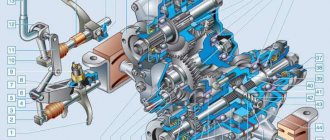
Gearbox of a Niva VAZ 2121 car, device
Device. Depending on the vehicle's configuration, it may be equipped with a four- or five-speed gearbox. The latter is designed on the basis of a four-speed gearbox, therefore the subsection describes the design and repair of a four-speed gearbox, and at the end of it - the features of the design and repair of a five-speed gearbox.
In both types of gearboxes, gears of the same name have single-digit gear ratios. Until 1987, the previously installed gearbox had different gear ratios: I – 3.242; II – 1.989; III – 2.89; IV – 1.00; Z.H. – 3,340.
The primary shaft 46 (Fig. 75) of the gearbox has two ring gears. The ring 1 with oblique teeth is in constant engagement with the gear 42 of the intermediate shaft, and the ring 3 with straight teeth is the crown of the 4th gear synchronizer; the intermediate shaft 40 is a block of four gears. The secondary shaft 10 is mounted on three bearings, with bearing 2 located in the socket of the primary shaft. Gears 7 and 8 rotate on heat-treated journals of the secondary shaft, and gear 11 on a steel bushing 12.
Rice. 75. Four-speed gearbox: 1 – constant engagement ring of the input shaft; 2 – lobed bearing; 3 – gear ring of the 4th gear synchronizer; 4 – sliding clutch for synchronizer of 4th and 3rd gears; 5 – synchronizer blocking ring; 6 – synchronizer spring; 7 – third gear gear; 4 – 2nd gear gear; 9 – hub of the sliding clutch for the synchronizer of 1st and 2nd gears; 10 – secondary shaft; 11 – 1st gear gear; 12 – gear bushing; 13 – intermediate bearing of the secondary shaft; 14 – reverse gear; 15 – outer cover; 16 – lever rod; 17 – thrust pad; 18 – elastic bushing; 19 – spacer sleeve; 20 – locking sleeve; 21 – inner cover; 22 – spherical washer of the ball joint; 23 – gear shift lever; 24 – back cover; 25 – oil seal; 26 – nut; 27 - seal spring; 28 – centering ring of the elastic coupling; 29 – centering ring seal; 30 – elastic coupling flange; 31 – rear bearing of the secondary shaft; 32 – spacer sleeve; 33 – reverse fork; 34 – reverse intermediate gear; 35 – reverse gear of the intermediate shaft; 36 – axis of the reverse intermediate gear; 37 – sliding clutch for synchronizer of 1st and 2nd gears; 38 – bottom cover; 39 – filler and control plug; 40 – intermediate shaft; 41 – gearbox housing; 42 – constant mesh gear of the intermediate shaft; 43 – front bearing of the intermediate shaft; 44 – bolt; 45 – washer; 46 – input shaft; 47 – front cover; 48 – rear bearing of the input shaft; 49 – clutch housing; 50 – breather
The synchronizer consists of a sliding clutch, a hub, a locking ring and a spring. The hub 9, rigidly connected to the secondary shaft, has external splines on which the sliding clutch 37 is located. The locking ring, with its internal crown, is connected to the synchronizer ring of gear 11 of the first gear and is constantly pressed by a spring towards the sliding clutch.
The reverse intermediate gear 34 is freely located on the axis 36. When reverse gear is engaged, gear 34 meshes with gears 35 and 14.
Gear shifting is carried out using a mechanical drive consisting of three rods on which forks are attached, which fit into the recesses of the sliding clutches 4 and 37 of the synchronizers, and the fork 33 into the recess of the intermediate gear 34 of the reverse gear. In the neutral and engaged positions, the rods are held by ball detents, and the simultaneous engagement of two gears is prevented by a locking device. The gear shift lever 23 with its head is placed in a ball joint and is pressed against it by a spring. Rotation of the lever is prevented by a guide pin that fits into the hole in the ball head of the lever and the support.
Disassembly
Before removing the rear cover, set the gear shift lever to neutral, unscrew the gear selector mounting nuts and remove the gear shift lever assembly. Then unscrew the nuts securing the rear cover and remove it. One of the cover fastening nuts is unscrewed from inside the gearbox housing with the bottom cover removed. When removing the rear cover, it must be moved not only backwards, but also turned to prevent it from touching the reverse and fifth gear gear block.
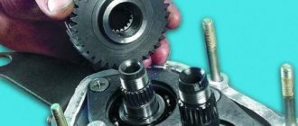
After removing the inner ring of the rear bearing 12 (Fig. 3-31) and the speedometer drive drive gear from the secondary shaft, loosen the bolts securing the cover 5 (Fig. 3-32) of the clamps and unscrew the bolts 2 and 4 securing the gear block and the fifth gear and reverse gear fork progress. Remove the oil deflector washer 9 (Fig. 3-31), and then the bushing 1 (Fig. 3-33) of the fifth gear gear and remove the rod 1 (Fig. 3-34) from the fork 2. At the same time, the spacer bushing 3 is removed from the rod. Then remove gear block 4 from the intermediate shaft spline.
Rice. 3-31. Five-speed gearbox rear:
1 – secondary shaft; 2 – reverse driven gear; 3 – fifth gear synchronizer clutch hub; 4 – synchronizer clutch; 5 – washer; 6 – gear shift lever; 7 – synchronizer blocking ring; 8 - gear and ring gear of the 5th gear synchronizer; 9 – oil deflector washer; 10 – 5th gear gear bushing; 11 – drive gear of the speedometer drive; 12 – rear bearing of the secondary shaft; 13 – oil seal; 14 – elastic coupling flange; 15 – nut; 16 - centering ring seal; 17 – centering ring; 18 – retaining ring; 19 – lock washer; 20 – driven gear of the speedometer drive; 21 – gear block bearing; 22 – gear block mounting bolt; 23 – gear block of 5th gear and reverse gear; 24 – rear cover of the gearbox; 25 – intermediate shaft
Rice. 3-32. Unscrewing the bolts securing the gear block and the 5th gear and reverse fork:
1 – reverse intermediate gear; 2 – bolt for fastening the gear block; 3 – fork rod; 4 – fork fastening bolt, 5 – clamp cover
Rice. 3-33. Removing the 5th gear bushing:
1 – bushing
Rice. 3-34. Removing the 5th gear and reverse fork rod and gear block:
1 – fork rod for 5th gear and reverse gear; 2 – fork for selecting 5th gear and reverse gear; 3 – spacer sleeve; 4 – gear block
At the same time, remove the reverse intermediate gear 1 (Fig. 3-35) from the axle, gear 3 assembled with the clutch and fork 4 from the secondary shaft.
Rice. 3-35. Removing the reverse intermediate gear, fifth gear gear assembly with synchronizer and fork:
1 – reverse intermediate gear; 2 – fifth gear engagement clutch; 3 – gear V gear with synchronizer; 4 – 5th gear and reverse fork
Remove washer 5 from the secondary shaft (Fig. 3-31), and then, using shaped mandrels (such as screwdrivers), remove hub 4 (Fig. 3-36) of the fifth gear synchronizer and reverse driven gear 2 from the key.
Rice. 3-36. Removing the reverse driven gear and 5th gear synchronizer clutch hub:
1 – intermediate shaft; 2 – reverse driven gear; 3 – axis of the reverse intermediate gear; 4 – fifth gear synchronizer clutch hub; 5 – secondary shaft; 6 – fork rod for 1st and 2nd gears; 7 – fork rod for 3rd and 4th gears
Note. Since 1992, washer 5 (see Fig. 3-31) on the secondary shaft has been canceled and the configuration of secondary shaft 1 and hub 3 of the 5th gear synchronizer clutch has been changed (on the secondary shaft, the diameter for the hub was 28 mm, it became 25 mm; the width of the hub seat the thickness of the washer has increased and the seat diameter has been reduced from 28 mm to 25 mm) The specified parts are not interchangeable with previously produced ones, therefore, when repairing a gearbox of an old design, follow the following rules:
- if washer 5 is changed, then the secondary shaft and hub are installed with the “old” design;
- If instead of a secondary shaft or hub, parts of the same name of a new design are installed, then they must be changed as a whole, that is, when replacing the hub, the secondary shaft also changes and vice versa. In this case, the washer is not installed.
Carry out further disassembly of the gearbox in the order described for the four-speed gearbox.
If necessary, disassemble the lever and gear selection mechanism, for which:
- remove the protective cover 10 (Fig. 3-37), locking and thrust rings 8 and 7, spring and spherical washer 5 from the gear shift lever;
- visually mark the location of the parts relative to the mark A marked on the guide plate in order to connect the parts in the same position during assembly;
- Having unscrewed the nuts from the fastening bolts, disconnect the parts of the gear selection mechanism and remove the lever 9, its ball joint 4 and rubber sealing rings 15.
Rice. 3-37. Gear selection mechanism:
1 – guide plate washer; 2 – guide plate; 3 – gear shift lever housing; 4 – ball joint; 5 – spherical washer; 6 – spring; 7, 8 – retaining rings; 9 – gear shift lever; 10 – protective cover; 11 – flange; 12 – reverse locking plate; 13 – spring; 14 – guide bar; 15 – sealing ring; A – risk
Professional repair of gearboxes for VAZ, GAZ, foreign cars on the same day!
WARRANTY for work according to the warranty card!
Gearbox repair from RUB 1,500.
Does not include the cost of spare parts. Guarantee!
Transmission replacement from RUB 3,000
with warranty (Excluding installation)
Sale of gearboxes from 5000 rub.
A gearbox after a major overhaul with a guarantee is always on sale.
Change of oil
Gearbox oil change, engine oil change
Seasonal tire fitting
The service is not available in all services.
Clutch replacement
A discount is provided when replacing a gearbox in all services.
Assembly
Assembly of the fifth gear, reverse gear and gear selection mechanism is carried out in the reverse order of disassembly, taking into account the following:
- Fasten the axis of the reverse gear intermediate gear until the shafts are installed in the gearbox housing with a torque of 78 N·m (8 kgf·m),
- before installing the fifth gear and reverse fork rod into the crankcase, install a spacer bushing on it;
- Press the inner ring of the bearing onto the fifth gear and reverse gear block, and the outer ring into the socket of the rear cover;
- Press the rear bearing of the secondary shaft onto the shaft to facilitate installation of the rear cover;
- . Install intermediate gear 1 (Fig. 3-35) for reverse gear, gear 3 and fork 4 at the same time;
- when assembling the gear shift lever, coat the ball head or ball joint with lubricant LSTs-15 or Litol-24;
- Tighten the gear block mounting bolt to a torque of 78 N·m (8 kgf·m).
ALER: I recommend looking at the comments made by firesanek
(Remaking the gearbox into a “torn package”).
During the assembly process, you need to remember one important operation - turning the shafts after each next installed part. The shafts should rotate easily, without jamming. If you feel tight rotation after installing any part, then this part is defective and must be replaced. Don’t be too lazy to do this, otherwise the work will be in vain, the gearbox will either not work properly or will quickly fail again.
Clamp the secondary shaft in a vice through a rag and use a grinder to make cuts on both sides at its rear end to secure the shank nut:
Attention! If the output shaft is worn or faulty, it makes sense to make cuts on the replacement shaft purchased only at the very end of the assembly process, after installing the gear shift mechanism and checking its operation. If there is a defect due to these cuts, you will not be able to return the purchased shaft to the store.
Lubricate the inner race of the input shaft bearing with oil or lithol. We place the input shaft on a wooden block, put the bearing on it with the groove with the locking washer facing up. Through a mandrel (pipe of suitable diameter) we place it on the shaft:
We install the spring ring and the locking ring, press it with light blows of a hammer through a chisel until it is completely fixed:
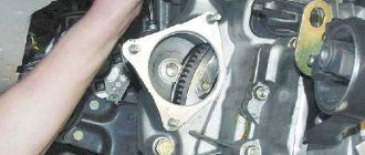
Carter
The Niva gearbox housing on the left side is equipped with a filler neck, and there is an analogue at the bottom. The holes are blocked with plugs with cone-type threads. The drain compartment has a magnet that traps metal particles that enter the oil due to wear of parts.
A breather is screwed into the top of the crankcase, which prevents the pressure in the gearbox from increasing due to excessive heating. If this element is faulty, lubricant may actively leak through the seals. In this case, the parts dry out, which increases the wear of the components.
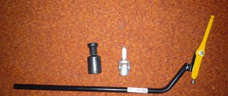
1. tension spring; 2. lock nut; 3. adjusting element; 4. cotter pin; 5. fork; 6. pusher; 7. mounting bolt; 8. working cylinder.
Correct shifting of transmission levers on a Chevrolet Niva
To use the lock installed on the Niva effectively, use the following recommendations from experts: When driving on a good quality road surface, install the front transfer case handle in front and the rear handle in the back. The front handle is moved back if the road becomes slippery. Once the slippery area has been passed, switch the levers to normal mode.
If the Niva is stopped, the lock may not engage when the clutch is depressed.
This occurs due to the alignment of the teeth with the gear teeth. How to turn on the transfer case on a Chevrolet Niva in this case? Moving as if on a turn, engage the lock. The differential will turn and the gear teeth will come closer to the teeth. If turning off is difficult, do it while the vehicle is moving, maintaining a minimum speed and squeezing the clutch.
How the cross-axle differential lock works on a Niva is clearly shown in the video: Among domestic car enthusiasts, the Chevrolet Niva is a fairly popular SUV that appeals not only to fans of extreme driving and adherents of measured driving outside the city. Many people know that one of the features of the transfer case switching on in a Chevrolet Niva of this brand is the presence of a transfer case in it.
Using this unit, you can enable downshifting, locking, or two functions at the same time, depending on the conditions.
The question of how the Niva Chevrolet transfer case should be used correctly is of interest to many happy owners of such a vehicle and those who only intend to purchase it. It should be immediately noted that you can engage both the lock and the transmission at the same time using the Chevrolet lever that changes gears. So, the lever switches to the right, and then immediately switches on the transfer case on a Chevrolet Niva to engage a lower gear.
To switch back to higher, the lever should simply be moved.
Using a Niva Chevrolet transfer case, in addition to switching on the transfer case on a Chevrolet Niva, the neutral gear is also switched on, and the car will remain securely in one place. The lock can be engaged at any time - in a normal gear, in a low gear - just switch the Chevrolet lever to the left. When is a low gear used? For what purposes is a transfer case even needed, when does it make sense to engage locking and low gear? Such seemingly simple, but at the same time serious questions will become clear when considering the following example.
How to install a new transfer case
If the dismantled transfer case of the Niva (its switching diagram is probably already clear) is in poor condition, and it is easier to replace it than to repair it, it is better to do so. Before installing a new device, you need to check the correct installation of the engine mounts in the brackets (the centering washers must coincide with the corresponding holes in the side brackets), and also check the tightness of the transfer case supports to the bottom of the body. If necessary, you need to immediately straighten the areas under the supports.
By placing a new transfer case in the vacant space, you do not need to fully tighten the fasteners of its suspension brackets. When moving the device lengthwise and crosswise, or even vertically, try to find the most suitable position in which the flanges of the drive and intermediate shafts will be located at the same level, parallel to each other, and the gap between them will be minimal.
After this, you need to return to their original places all the previously removed adjusting shims that are installed under the supports, and tighten the fastening nuts of the suspension brackets. Next, connect the front and rear shafts to the transfer case shafts, and the flexible shaft to the speedometer drive. The wires are connected to the differential lock control dump sensor.
Manual gearbox VAZ gear shift diagram, general arrangement
General structure of manual gearboxes on VAZ
VAZ manual gearboxes are very reliable, unpretentious gearboxes, their gearshift scheme is the most standard, no exotic ones. And this is a huge plus, since their maintenance and repair are just as simple and straightforward. They have to be repaired relatively rarely, since they perfectly hold the torque from the ring shaft of VAZ engines, even forced ones. For comparison, many manual gearboxes have difficulty maintaining the torque of stock engines, comparable in power to VAZ ones, and very quickly fail at the slightest increase in engine power. What makes VAZ manual transmissions so durable? Let's look at the diagram of their design and understand why they are good and what their shortcomings are.
Design of a 4-speed manual transmission VAZ 2101 - 2106. General diagram of the gearbox.
Design of a 5-speed manual transmission VAZ 2106 - 2107. General diagram of the gearbox.
Design of a 5-speed manual transmission VAZ 2108 - 2110. General diagram of the gearbox.
The device of a 5-speed manual transmission Lada Priora, Kalina. General diagram of the gearbox.
The first VAZ boxes of cars produced in the 70s had a gearbox copied from Fiat cars, but they only had a common device. VAZ manual transmissions were reinforced; shafts and gears made of stronger metal were installed on them, which, with relatively not very powerful engines, allowed these boxes to “run” without repair for 10 years or more. Of course, VAZ boxes also have a phenomenal drawback that has not been eliminated to this day, I think many have understood what we are talking about, this is the howl of the box. There is only one reason for this - insufficient technological precision in the processing of bearings and gears. This shortcoming can be corrected by changing technology and processing equipment, but at the moment (2020), the company has not taken this step and all manual transmissions produced by VAZ Lada are, so to speak, howling. Some to a greater extent, others to a lesser extent, which is quite surprising.
New cable transmissions installed on car models with 16-valve engines have become much quieter even when braking the engine. They have reinforced synchronizers (which, however, cannot be called problem-free). They are capable, according to the passport data, of withstanding a torque of 160 Nm. In practice, they work properly even under much higher loads when the car engine is boosted.
You should not think that we are deliberately praising VAZ manual gearboxes; we only noted their well-deserved positive qualities. But, of course, they encounter problems during operation. Let us note the most common malfunctions, their causes and solutions.
Basic transfer case malfunctions
All malfunctions in the operation of the transfer case immediately manifest themselves in external symptoms, based on which the vehicle owner can judge the current situation. Such manifestations include the following.
Vibration when starting to move the car
The main disease of the Niva is the vibration that reverberates throughout the entire body of the car. The reason for this unpleasant phenomenon is often caused by improper alignment of the VAZ Niva transfer case. Most often, vibration occurs on VAZ 21213/21214 models, because in these cars the transfer case is fixed only on two supports located on the sides of the body. For comparison, the transfer case on the Chevrolet Niva is already installed on three supports. However, before you begin adjusting the position of the transfer case, you should make sure that it is involved in the occurrence of vibrations.
It is quite possible that it is caused by other chassis parts. For example, the cardan shafts are poorly secured, the car’s wheels are not balanced, there is play in the cardan crosspieces (play in the rear cardan crosspieces especially affects the occurrence of vibration) and vibration emanating from the power unit.
The appearance of vibration at the beginning of movement is also facilitated by loose fastenings of the transfer case mounting supports or torn rubber on the transfer case supports themselves.
Vibration at speed
If, having picked up a speed of up to 80-100 km/h, you notice that the floor is vibrating in the area of the front seats, at the earliest opportunity you need to check the operation of some components and mechanisms.
It is quite possible that during assembly the relative position of the intermediate shaft elements was disturbed, the elastic coupling became delaminate, or the constant velocity joints were assembled incorrectly (not to mention the fact that they could simply wear out).
It would also be useful to check the presence of balancing washers under the bolts of the elastic coupling - they are often lost. If several such problems are detected, the best solution to the problem is to replace the intermediate shaft assembly.
Differential
This mechanism is a kind of distributor of traction forces coming from the motor to the wheels. An important feature is that the latter have the ability to rotate at different speeds. The importance of having a differential mechanism is due to the fact that during turning maneuvers, the wheel located inside makes fewer revolutions when compared with the number of turns of the outer wheel.
In the absence of a differential mechanism, this would cause detrimental consequences, such as wear and damage, because the result would be the following: when turning, one wheel would be in a slip state, and the second would simply rub against the road surface. The design features of the Niva transmission provide for the presence of 3 differentials. They are located in each of the bridges and in the transfer mechanism.
When the car moves on a flat road and in a straight line with differentials, the traction force is divided equally between all 4 wheels. If there is insufficient adhesion of the wheels to the surface or slipping occurs, the differentials will redistribute the load on the slipping and sliding wheel so that the first receives more force, and the second, accordingly, less.
We have already mentioned UAZ. Despite many similarities, it should be understood that the VAZ’s all-wheel drive is made in the “pat-time” style. This means that when connected, the axes are firmly connected to each other, and rotation occurs at the same speeds. This device imposes some restrictions on the use of all-wheel drive - it can only be used in cases where road conditions allow slipping. In cases with hard asphalt roads and highways, it is recommended to switch the car to single-drive mode.
Other parts and mechanisms
Among other elements of the unit in question, the following devices can be noted:
- Transfer of movement back. It does not have a synchronizer; activation is carried out by introducing an intermediate gear with a driving analogue of the secondary shaft and the same part on the intermediate roller.
- The Niva-2121 gearbox has a control drive consisting of three rods that are aggregated with forks. The last elements are placed in the sockets of the sliding clutches, and the reverse gear analogue is placed in the groove of the intermediate gear.
- The lubrication mechanism involves processing the parts of the assembly by splashing. The shafts are sealed with oil seals; the secondary shaft of the fifth gear has an oil deflector in the form of a washer. The filled oil level should reach the bottom edge of the fill socket.
Description of possible problems with the transfer case
During the operation of off-road vehicles, parts and components of the transfer case gradually become unusable due to wear. Most often, the following interruptions in the operation of the mechanism occur:
The transfer case is overheating.
Changing the oil in the transfer case Niva 2121
To ensure the performance of the vehicle, it is necessary to carry out timely maintenance. Changing the oil is included in the mandatory list of machine maintenance work. To change consumables in the Niva 2121 transfer case, you will need 0.8 - 1.5 liters of gear oil.
The frequency of replacing lubricating fluid is equal to 45,000 km of distance traveled. The first procedure is carried out after 60,000 km, and then in accordance with the established schedule.
Attention: If problems arise with shifting gears, extraneous sounds, vibrations and vibrations, it is necessary to check the condition and amount of oil in the transfer case and the transmission as a whole.
The procedure for changing the oil in the transfer case of a Niva SUV:
- warm up car systems and mechanisms, to do this you need to start the engine and drive a short distance;
- install the machine on an overpass or over a special inspection hole;
- clean the filler and drain plugs of the transfer case from dirt and dust;
- place a container under the drain to collect waste material;
- unscrew the plugs and drain the liquid;
- remove metal fragments, shavings, splinters and other wear elements;
- screw in the plug;
- pour into the washing liquid (about one liter);
- start the engine;
- move the lever through the transfer case gears with slight delays;
- turn off the engine;
- drain the flushing composition;
- fill the transfer case with new oil;
- check the oil level;
- if necessary, add the required amount.
For the transfer case of the Niva 2121 SUV, transmission oils of the famous brands Mobil, TNK, Castrol of the GL-4 class are most often used.
vote
Article rating
In what cases is this procedure necessary?
With proper operation, the gearbox can last quite a long time, since it is a self-sufficient design element that does not require frequent maintenance. On the Chevrolet Niva, the gearbox is designed in such a way as to satisfy the off-road ambitions of the crossover, because initially this car was equipped with all-wheel drive in order to overcome various obstacles. This means that the car’s transmission is designed for increased loads. But it is necessary to take into account such processes as metal fatigue and the production of parts. Over time, under increased loads, the gearbox begins to operate for a long time, experiencing overheating, which leads to expansion of parts and increased wear.
There may be several main reasons when it is necessary to remove the gearbox:
- Dismantling to completely replace the entire mechanism. It is usually rarely used in practice, since in most cases it is possible to repair an old gearbox except in cases where the housing is damaged.
- To carry out maintenance. Components can be cleaned or consumables can be replaced: oil seals, slides or gaskets, depending on the specific case.
- When carrying out other repair work, when the gearbox will prevent access to the desired unit.
Before removing the gearbox, you must carefully study the feasibility of these actions. For processes such as changing the oil, installing a rocker seal or clutch cylinder, removing the box is not required.