One of the main elements of a car’s ignition system, without which it is not possible to ignite the combustible mixture in the internal combustion engine cylinders, is the ignition module. By generating high voltage pulses, which creates a spark on the spark plugs, the module ensures ignition of the fuel mixture at a certain point in time.
This moment is determined by a preliminary setting corresponding to the factory parameters. Changing these parameters during vehicle operation can lead to problems in engine operation and serious malfunctions (even failure of the internal combustion engine).
Next, we will look at the design and operating principle of the module using the VAZ 2114 as an example, determine the main causes of the malfunction and how to eliminate them, and also describe several diagnostic methods.
VAZ 2114 ignition module and its purpose
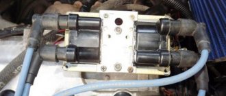
The VAZ 2114 8 valve ignition module is a special device, the purpose of which is to convert electrical energy coming from the generator into a current with a very high voltage. In addition, the module also plays the function of a distribution device that diverts increased voltage to the spark plugs.
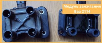
By its design, it is a paired system, including two pairs of windings, as well as a commutator. The purpose of the latter is to alternately switch the incoming low-voltage electricity from one coil to another.
The ignition module, unlike ignition coils (which were used in earlier periods of the automotive industry), has not two, but four pairs of terminals, which are used to connect high-voltage wires, which, in turn, go to the spark plugs.
Pulses in the module, in this case, appear alternately in pairs - first on connectors 1 and 4, and then on 2 and 3. The ignition module itself is controlled using a special electronic unit.
Ignition module block
Video “Visual guide to replacing MH”
The STO TONN channel presented a visual aid for replacing the ignition module on a domestic VAZ 2114 car.
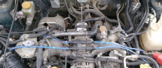
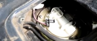
They brought a “wonderful” car to our service center, as the owner put it. And the miracle is that the owner declares: he changed EVERYTHING, the car worked on two cylinders and still works. We ask how they discovered that two cylinders were not working? The owner replies: I checked the spark, there is no spark on the second and third cylinders. I installed new wires, installed a new ignition module for testing, even installed new ECUs (brains), no spark in 2nd and 3rd and that’s it. The wiring says they checked it, everything is fine, there are no short circuits. Well, truly MIRACLES.
Here it is, our wonderful machine! VAZ 2114
Fig.1
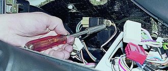
Let's start in order. We connect diagnostic equipment and read errors, if of course there are any. We have several of them. We have installed the control unit January 7.2
Possible reasons for failure of the ignition module
Generally speaking, the ignition module is a completely reliable device, and its breakdowns are quite rare. At the same time, the weakest point inside the module is the primary windings of each of its coils - it is on these windings that high voltage is generated, so sometimes breakdowns, breaks or melting of the turns can occur there.
The main reasons causing overloads and improper operation of coils, leading to their breakdowns, are:
- use of unsuitable, faulty or dirty spark plugs;
- frequent spark checks;
- operation of the module with disconnected or damaged high voltage wires;
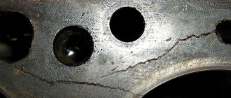
- high vibration of the fixed module, causing damage to the factory soldering inside it;
- poor contact inside the low-voltage wire connectors.
Ignition module failure
In addition, a fairly common cause is the usual ingress of water into the module (which often happens when the car is operated in a damp environment or after washing).
What should I do if the problem remains after replacing the module?
If, after performing the repair, problems in the operation of the MH remain, then there is a possibility that the cause of the problem was not in the module. It is necessary to diagnose the remaining elements of the ignition system.
Spark plugs and ignition system
Features of checking spark plugs and other components:
- Before dismantling the devices, it is necessary to disconnect the ends of the high-voltage cables. Their condition is checked for damage. Defects in the tips often lead to malfunctions in the spark plugs. If there is damage, the wires are replaced. It is also necessary to assess the condition of the “high-voltage workers” themselves. They are not allowed to have any defects or damage to the insulation.
- After disconnecting the tips, the spark plugs are dismantled and a special spark plug wrench is used to unscrew them.
- After dismantling, the condition of the devices is assessed. The color of the parts must be brown; carbon deposits and soot on the electrodes are not allowed. If there are uncharacteristic marks, the devices are cleaned using a metal brush or fine-grained sandpaper. For a better effect, the electrodes of the candles can be heated on the stove.
- The condition of the gap between the part and the electrode element is checked. If it is too large, this indicates that the device is not working correctly. The spark plugs will need to be replaced.
Signs of coil malfunction
Before starting an instrument test, you can try to determine whether the ignition coil of the VAZ 2114 8-valve injector is working by indirect signs (in some cases they are enough to verify a breakdown).
These include:
- instability (intermittency) of idle speed;
- the engine gains speed with great difficulty;
- “triple” when the engine is running;
- The speed gain while driving occurs in strong jerks.
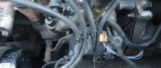
Connecting the ignition unit
If these signs are present (especially if there are several of them), you can either immediately replace the faulty module, or finally establish the fact of its malfunction using instrumental analysis.
Examination
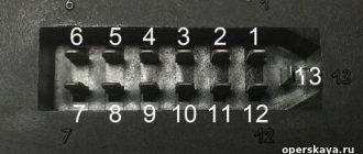
Often problems with MH begin after replacing high-voltage power wires. Many people may simply make a mistake by mixing up the connection points to the candles. The pin numbering scheme is presented below.
Also, owners of the injection-type VAZ-2114 often replace the standard wires with modern silicone analogues. This is absolutely impossible to do. Silicone high-voltage wires have significantly higher resistance. When replacing, it is also important to consider the length of each wire. Standard wiring has the following parameters:
- The wire of cylinder 1 has a length of 56 cm and an operating resistance of 2.5 to 3.8 Ohms.
- A 44 cm long wire with an operating resistance of 2 to 3 Ohms goes to the second cylinder.
- 3 wire 36 cm long, resistance from 1.6 to 2.6 Ohms.
- 4 wire 32 cm long, resistance from 1.4 to 2.1 Ohm.
How to check the malfunction of the VAZ 2114 ignition module on your own?
In order to start checking, you will need a measuring device - a tester. Before starting the measurement, the wire blocks are removed from the connectors. Each block has its own slot (A, B, C, D).
Checking the VAZ 2114 ignition module with a multimeter:
- turn on the car engine;
- set the multimeter switch to measure direct current up to tens of volts;
- one of the probes of the device is connected to connector D, the second to ground. If there is power, the screen will show 12 volts;
- switch the multimeter to ohmmeter mode up to tens of ohms;
- one probe is connected to connector C, the other to ground. If everything is in order, the device will show less than 1 Ohm;
- switch the multimeter to voltmeter mode up to tens of volts;
- one probe is connected to connector B, the other to ground. If a voltage of at least 0.3 Volts is displayed, then everything is fine (a clear pulse comes from the Hall sensor);
- The last measurement with connector A is carried out exactly as in the previous case.
Checking the ignition unit with a multimeter
Before you start testing the ignition module, you should carefully check the quality and reliability of the contact of all wires approaching and departing from it - perhaps this is the only reason.
Another testing method is to directly check the secondary coils for breakdown.
It is performed according to the following scheme:
- all wires are removed from the connectors;
- the multimeter is set to ohmmeter mode up to tens of kOhms;
- the probes are alternately installed in paired connectors (1 and 4, 2 and 3);
- if the windings are in good condition, both measurement results will be the same (on average, they should be equal to 5.4 kOhm). If the resistance turns out to be much higher, then there is an internal break in the turns; if it is much lower, there is a breakdown.
Checking high voltage wires
Also, there is another, easiest way to check the ignition coil of a VAZ 2114 - simply replace it with a new one, completely similar. If after replacement the car began to work properly, then the reason was definitely in the module.
Checking the connector contacts
We have already carried out a preliminary check and made sure that power is supplied to the ignition module. Now it’s worth dealing with the contacts separately. With the ignition on, you need to connect a test lamp to contact A and contact B.
The control can be a regular low-power 12-volt lamp with soldered wires, or you can use a car test probe with a 12-volt voltage indicator.
Checking the ignition module
To check the functionality of the module, we attach the contacts from the test lamp or probe to terminals A and B , then crank the engine with the starter.
If the lamp begins to blink, the module produces a voltage break similar to a contact breaker.
In this case, everything is in order with contacts A and B.
If the lamp does not respond to the starter, the module is definitely faulty.
Ignition module repair
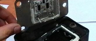
Due to the fact that the design of the module consists of a pair of coils, its maintainability is extremely low. So, if there is a breakdown, breakage, fusion of the turns, as well as other damage inside the coils, then nothing can be done here - all that remains is to replace the failed module with a new, similar one. The only case when you can try to solve the problem without purchasing a new device is if the solder is damaged.
This can be found out by testing (using the methods described above). If the serviceability of the secondary windings has been established, you can try to open the module cover and visually determine the damage to the soldering.
If such damage cannot be determined, then you can simply try to thoroughly solder all the contacts inside, then install the module in place and start the engine - if this was the cause of the breakdown, then the car will start working properly again.
WE MAKE THE REPLACEMENT WITH OUR OWN HANDS
Repairing the ignition module of the fourteenth is a dubious task, since a device that has once failed will continue to “delight” you in the future, so it is much easier to install a new, normally functioning unit. Moreover, it is impossible to do a complete repair of the unit with your own hands - you will need to go to a service station.
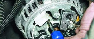
Removing the ignition module is performed as follows:
- Remove the “-” terminal from the battery;
- Unscrew the tips of the spark plugs;
- Disconnect the block from the LV module power wires;
- We remove the high-voltage wires - you just need to remove them from the special connectors;
- Unscrew the bolts that secure the bracket holding the unit on the crankcase of the fourteenth engine;
- We dismantle the assembly together with the bracket;
- Disconnect the device from the bracket.
To do everything yourself you will need 13 and 17 keys, a screwdriver and a set of hex keys. Knowing how to check the ignition module, it will take 1-2 hours to identify faults and, if necessary, replace the unit.
Other reasons
If, after checking the ignition module of an injection-type VAZ-2114 car, no malfunction was identified, then you should pay attention to breakdowns or improper operation of adjacent devices.
- Powertrain control unit. It happens that after an electrical short circuit, the ECU loses its internal settings. To restore functionality, you need to disconnect the “+” terminal from the battery and connect it again. The ECU will enter a temporary reboot, and the module's operation may be restored. It is also worth carrying out professional diagnostics of the on-board network.
- Crankshaft position sensor. An important source of pulse signals. Its data affects the distribution of voltage from the ECU to secondary devices. It is necessary to check the functionality of this element, its wiring, and the protective fuse. If necessary, replace faulty parts.
- Hall Sensor. This device is responsible for the distribution of pulses. Signals are generated due to contact connection during rotation of the device rod. Any deviations in the supply of signals affect the operation of the ignition module.
- Generator. The high charge current of this mechanism often leads to complete burnout of the secondary winding of the MC. The first problem may be a faulty fuse. If such a problem is detected, it is worth checking the amount of voltage coming from the generator.
The system, which includes a Hall sensor, DPKV and ignition module, works by calculating the position of the crankshaft. This is how the exact order of the spark cycle on the cylinders is achieved.
Important! Very often, the performance of the MH is affected by careless operation of this device. The cause of failure may be:
- Lack of contact with the “mass”. This occurs when the 3 bolts securing the device are insufficiently tensioned. Periodic loss of contact leads to a break in the circuit. The newly appeared contact causes the discharge of a current of greater strength. This leads to internal burnout of the secondary winding of the coils.
- Lack of contact on spark plug caps. A poor connection leads to contact vibration, often high-voltage wires fly out and short to ground. This leads to damage to the MZ discharge contactor.
- Poor contact or oxidation at the battery terminals. It also leads to a short-term but powerful discharge of the primary winding.
- Spark plug gap. The manufacturer sets a fixed spark plug gap. The maximum value for spark plugs installed on injection engines can be 1.3 mm. A large gap leads to a spark hitting the housing. The spark is simply deflected to the side. A small gap size can lead to breakdown of high-voltage wires or the ignition coil itself. The high voltage pulse current is simply discharged back into the circuit.
Many car enthusiasts try to disassemble and repair ignition modules themselves. With proper knowledge of electronics, only the discharge regulator can be repaired. The coils will have to be rewound. But the main difficulty lies in the subsequent sealing and insulation of the inductors. Any remaining cracks will cause breakdown and failure. It is better to purchase and replace the MZ with an exact analogue.