At different times, different engines were installed on the VAZ-2110 car, both carburetor and injection. However, regardless of the type of power system and the number of valves (8 or 16), all engines are assembled on the unit base of the old engine 21083 and 21093. The most progressive of these engines is the 16-valve 1.6-liter VAZ 21124 engine with a power of 89 horsepower. Today we will touch on the ignition module for 8-valve engines 2111 and 21114 (1.6 l), check its performance and find a suitable replacement for the failed module.
Contactless engine ignition system 2110
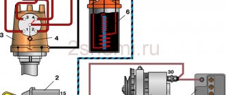
Diagram of a contactless ignition system.
The contactless ignition system consists of an ignition distribution sensor 2, a switch 4, an ignition coil 1, spark plugs 3, an ignition switch 5 and high voltage wires. The power supply circuit for the primary winding of the ignition coil is interrupted by an electronic switch. Control pulses are supplied to the switch from a contactless sensor (Hall sensor) located in the ignition distributor sensor.
Ignition distributor sensor - type 40.3706 or 40.3706–01, four-spark, unshielded, with vacuum and centrifugal ignition timing regulators, with a built-in microelectronic control pulse sensor (Hall sensor).
Switch – type 3620.3734, or 76.3734, or RT1903, or PZE4022. It converts the sensor control pulses into current pulses in the primary winding of the ignition coil.
Ignition coil - type 3122.3705 with a closed magnetic circuit, dry or type 8352.12 - oil-filled, sealed with an open magnetic circuit. Spark plugs - type A17DVR, or A17DVRM, or A17DVRM1, or FE65PR, or FE65CPR with noise suppression resistors.
Ignition switch - type 2110–3704005 or KZ–881 with an anti-theft locking device, with a lock against re-starting the starter without first turning off the ignition and with an illuminated socket.
The ignition system of the 2110 engine is an injector.
The VAZ 2110 injection engine control system is a group of complex electronic and mechanical devices that require certain knowledge and approaches to repair. It consists of a set of sensors, actuators and a central control unit - the controller.
Location of elements of the injection engine control system 2111
- mass air flow sensor;
- coolant temperature sensor;
- knock sensor;
- adsorber for gasoline vapor recovery system;
- crankshaft position sensor;
- throttle pipe (it contains a throttle position sensor and an idle speed regulator);
- speed sensor (located on the gearbox);
All injector actuators are controlled by a central unit—the controller. The information received from the sensors is read by the controller and, based on them and the control program embedded in it, signals are sent to various actuators. The engine control unit may vary in modification and firmware version.
There are two distributed injection systems:
- With feedback.
- No feedback.
A system with feedback differs from a system without it by the presence of a neutralizer and an oxygen sensor. The DC provides feedback and participates in calculations of the optimal gasoline-air ratio of the fuel-air mixture, ensuring optimal operation of the converter. Thanks to this, higher levels of toxicity standards and emissions of harmful components into the atmosphere are achieved. Also in this system there is a system for collecting gasoline vapors - an adsorber.
The above devices are not installed in the open-loop injection system. To ensure toxicity standards, there is an adjustment of CO in the exhaust gases using a CO potentiometer.
The modified 2112 engine uses a sequential distributed fuel injection system - phased injection. It has another device - a phase sensor installed near the camshaft. It determines the moment of the end of the compression stroke in the 1st cylinder, and fuel is supplied by injectors to the cylinders in the sequence corresponding to the ignition order in them: 1c - 3c - 4c - 2c.
Non-contact ignition system for carburetor engine VAZ-2110
The contactless ignition system consists of a distributor sensor, a switch, an ignition coil, spark plugs, an ignition switch and high and low voltage wires
Ignition distributor sensor type 40.3706 or 40.3706-01 , four-spark, unshielded, with a control pulse sensor (Hall) and built-in vacuum and centrifugal ignition timing regulators.
The distribution sensor performs two main functions: firstly, it sets the moment of spark formation depending on its initial setting, the number of revolutions of the crankshaft and the load on the engine, and secondly, it distributes high voltage pulses (“spark”) among the cylinders in accordance with the order of their work. For this purpose, a rotor (runner) mounted on the distributor sensor roller is used.
In order to avoid mistakes during assembly, the slider and the cover of the sensor-distributor are installed on the sensor-distributor in only one position, as well as its roller.
The slider contains a 1 kOhm noise suppression resistor.
You can check the functionality of the Hall sensor by assembling the circuit shown in Figure 2.
Slowly rotating the ignition distributor shaft, monitor the voltmeter readings.
The voltage should change sharply from the minimum (no more than 0.4 V) to the maximum (no more than 3 V less than the supply voltage).
If a steel screen with slots touches the sensor (determined by slight jamming or a scratching sound when the roller rotates, as well as after partial disassembly of the sensor-distributor), check the axial play of the roller (no more than 0.35 mm, adjusted by selecting washers) and the fit of the screen on roller If necessary, replace the roller assembly.
A faulty Hall sensor cannot be repaired (except for a break in the wires between the sensor itself and the block on the sensor-distributor housing).
You can roughly assess the serviceability of the vacuum regulator directly on the car.
With the engine running, disconnect the vacuum hose leading to the regulator from the carburetor fitting.
If you now create a vacuum in the hose (you can use your mouth), the engine speed should increase, and when the vacuum is removed, it should decrease again.
The vacuum should remain for at least a few seconds if the hose is pinched.
You can visually verify the functionality of the vacuum regulator by partially disassembling the sensor-distributor and applying a vacuum to the inlet fitting of the regulator.
In this case, the plate with the Hall sensor should rotate at an angle of 7±1°, and when the vacuum is removed, return back without jamming.
Accurate testing and adjustment of vacuum and centrifugal ignition timing regulators is carried out on special stands.
It is not recommended to do this at home. If the vacuum regulator fails, it should be replaced; if the centrifugal regulator fails, the sensor-distributor should be replaced.
A switch type 3620.3734 or 76.3734 opens the power supply circuit of the primary winding of the ignition coil, converting the sensor control pulses into current pulses in the ignition coil.
The switch is checked using an oscilloscope using a special method; it is not repairable.
Do not disconnect the switch connector while the ignition is on - this may damage it (as well as other components of the ignition system).
Ignition coil - type 3122.3705 - dry, with a closed magnetic circuit, or type 8352.12 - oil-filled, with an open magnetic circuit.
Data for testing: resistance of the primary winding at 25°C – 0.43±0.04 Ohm (3122.3705) or 0.42±0.05 Ohm (8352.12), secondary winding – 4.08±0.4 kOhm (3122.3705) or 5±1 kOhm (8352.12). Insulation resistance to ground is at least 50 MOhm.
Spark plugs - type A17DVR, or A17DVRM, or A17DVRM1, or their imported analogues (with noise suppression resistance 4-10 kOhm).
High-voltage wires – with a distributed resistance of 2550±270 Ohm/m. Do not touch high-voltage wires while the engine is running - this may result in electrical injury.
It is also prohibited to start the engine or allow it to operate with an open high-voltage circuit (removed wires or sensor-breaker cover) - this can lead to burnout of the insulation and failure of the electronic components of the ignition system.
As an exception, a short-term check of the ignition system “for spark” is possible, and the contact of the high-voltage wire being tested must be securely fixed at a distance of 5-10 mm from the vehicle ground. Do not hold the wire with your hands or tools (even with insulated handles).
Nothing happens when I turn the key in the lock.
If the starter does not turn, then the spark has disappeared between the ignition switch and the starter. This most often happens when the battery is low or faulty. When checking with a voltmeter, a normal battery should show at least 11.8 V, and when diagnosing with a hydrometer in each jar during measurements, the data should not be lower than 1.22.
Other causes of problems with engine starting may be breakdowns:
- The ignition lock cylinder makes itself known the moment you insert and turn the key. If this happens too easily or, on the contrary, you feel difficulties, then the problem is in the lock. It needs to be replaced with a working one.
- The starter or ignition relay is located under the instrument panel. Only a qualified auto electrician can check the functionality of these units. On your own, you can simply replace the relay with a working one.
- The starter’s “retractor” often jams; in this case, the spark could disappear right along the way. Experienced car enthusiasts recommend hitting the starter in the field with a key or something heavy, but just be careful with the force. If you managed to get to the garage, you can check the starter using the battery. Ideally, when you press the starter housing at the zero phase, and stretch the wire with the “crocodile” from the positive to the “retractor”, the unit should “come to life”. If nothing happens, then the problem is in the “retracting” part. If the relay is working, the problem may be in the brushes; it makes a loud noise and the starter does not turn if the bendix is faulty.
- Often the spark disappears at the point of power supply to the starter. The circuit can be checked using a multimeter. In this case, you need an assistant who will turn the key at the moment when you begin to take measurements.
The spark in the VAZ-2110 often disappears for another reason - banal oxidation of the contacts. We have already mentioned cleaning them from oxidation; if servicing the ECU did not help, then you should look at other wires. For example, trace the course of a mass conductor. The most vulnerable places on it are where it contacts the body and approaches the battery terminal. If a fault is found at the terminal, replace the wire. At the point of contact with the body, it is enough to simply clean it with a metal brush.
Possible malfunctions of the contactless ignition system and methods of elimination
Engine won't start
- The switch does not receive voltage pulses from the contactless sensor:
— a break in the wires between the ignition distributor sensor and the switch; — Do the following: — check the wires and their connections; replace damaged wires;
— the contactless sensor is faulty — check the sensor using an adapter connector and a voltmeter; faulty sensor replace
- No current pulses are supplied to the primary winding of the ignition coil:
— a break in the wires connecting the switch to the switch or to the ignition coil — Do the following: — check the wires and their connections; replace damaged wires;
Stage one
Typically, the symptoms of the problem are as follows: the starter rotates properly in its standard mode, but the engine does not want to start. One of the most likely causes is a fuel pump that does not start. By the way, on injection “tens” it is submersible and is placed directly in the tank.
View gallery
You can check the element by the presence of operating sound. Turn on the ignition - there should be a hum in the area of the rear seats. Sometimes he is missing. In this case, you should check the fuses. The VAZ-2110 is an injection car, and the fuse box is located on the side of the center console on the front passenger side. It is necessary to unscrew the fasteners, then remove the cover, check the fuses for functionality and, if necessary, replace them. If the elements are fully operational, then you need to check whether the relay will turn on, both the main one and the fuel pump. You can feel the moment of switching on with your finger. A characteristic click will also be heard.
If the fuel pump is operational, use a pressure gauge to check the presence of fuel in it. If there is no pressure gauge, then press the spool at the end of the fuel rail. This element may be contained in a protective cap. The pressure will be quite noticeable, although its power cannot be determined. A running pump and no pressure may indicate an obstruction in the fuel line. This may be caused by a clogged fuel filter.
Elements of the VAZ-2110 ignition system
The ignition system of the VAZ-2110 is contactless or microprocessor-based. This section discusses the contactless ignition system. It consists of a distributor, commutator, ignition coil, spark plugs, ignition switch and high and low voltage wires.
Fig.28. Scheme of the contactless ignition system of the VAZ-2110
1 – battery; 2 – generator; 3 – plug connector; 4 – ignition switch; 5 – sensor-distributor; 6 – switch; 7 – candles; 8 – ignition coil.
Ignition distributor (distributor) VAZ-2110 type 40.3706 or 40.3706-01, four-spark, unshielded, with a control pulse sensor (Hall) and built-in vacuum and centrifugal ignition timing regulators.
Fig.29. Distributor of the ignition system VAZ-2110
a – device; b – diagram of the operation of the centrifugal regulator; 1 – coupling; 2 – body; 3 – vacuum regulator; 4 – vacuum regulator rod; 5, 7 – covers of the vacuum regulator; 6, 12 – springs; 8 – fitting for supplying vacuum; 9 – diaphragm; 10 – centrifugal regulator; 11 – contactless sensor; 13 – driven plate of the centrifugal regulator with screen; 14 – roller with the drive plate of the centrifugal regulator; 15 – weights; 16 – oil seal; 17 – cover; 18 – rotor; 19 – protective screen; 20 – holder of the front roller bearing assembled with the sensor support plate; 21 – washer for fastening wires; 22 – sensor support plate with bearing.
The VAZ-2110 distributor performs two main functions: firstly, it sets the moment of spark formation depending on its initial installation, the number of revolutions of the crankshaft and the load on the engine, and secondly, it distributes high voltage pulses (“spark”) among the cylinders in accordance with the order of their work. For this purpose, a rotor (runner) mounted on the distributor sensor roller is used.
In order to avoid mistakes during assembly, the slider and ignition distributor cap are installed on the distributor sensor in only one position, as well as its shaft. The slider contains a 1 kOhm noise suppression resistor.
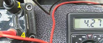
Fig.30. Scheme for checking the Hall sensor on a VAZ-2110 car
1 — ignition distributor; 2 - a voltmeter with a scale limit of at least 15 V and an internal resistance of at least 100 kOhm; 3 — view of the plug connector of the ignition distributor.
You can check the functionality of the Hall sensor by assembling the circuit shown in the figure. Slowly rotating the VAZ-2110 distributor shaft, we monitor the voltmeter readings. The voltage should change sharply from the minimum (no more than 0.4 V) to the maximum (no more than 3 V less than the supply voltage).
If a steel screen with slots touches the sensor (determined by slight jamming or a scratching sound when the roller rotates, as well as after partial disassembly of the distributor), check the axial play of the roller (no more than 0.35 mm, adjusted by selecting washers) and the fit of the screen on the roller.
If necessary, replace the roller assembly. A faulty Hall sensor cannot be repaired (except for a break in the wires between the sensor itself and the block on the distributor housing of the VAZ-2110 ignition system).
You can roughly assess the serviceability of the vacuum regulator directly on the car. With the engine running, disconnect the vacuum hose leading to the regulator from the carburetor fitting.
If you now create a vacuum in the hose, the engine speed should increase, and when the vacuum is removed, it should decrease again. The vacuum should remain for at least a few seconds if the hose is pinched.
You can visually verify the functionality of the vacuum regulator by partially disassembling the VAZ-2110 distributor and applying a vacuum to the inlet fitting of the regulator.
In this case, the plate with the Hall sensor should rotate at an angle of 7±1°, and when the vacuum is removed, return back without jamming. Accurate testing and adjustment of vacuum and centrifugal ignition timing regulators is carried out on special stands.
It is not recommended to do this at home. If the vacuum regulator fails, it should be replaced; if the centrifugal regulator fails, the ignition distributor should be replaced.
A switch type 3620.3734 or 76.3734 opens the power circuit of the primary winding of the VAZ-2110 ignition coil, converting the sensor control pulses into current pulses in the ignition coil.
The switch is checked using an oscilloscope using a special method; it is not repairable. Do not disconnect the switch connector while the ignition is on - this may damage it (as well as other components of the ignition system).
Ignition coil VAZ-2110 - type 3122.3705 - dry, with a closed magnetic circuit, or type 8352.12 - oil-filled, with an open magnetic circuit.
Data for testing: resistance of the primary winding at 25°C – 0.43±0.04 Ohm (3122.3705) or 0.42±0.05 Ohm (8352.12), secondary winding – 4.08±0.4 kOhm (3122.3705) or 5±1 kOhm (8352.12).
Insulation resistance to ground is at least 50 MOhm. Spark plugs VAZ-2110 - type A17DVR, or A17DVRM, or A17DVRM1, or their imported analogues (with noise suppression resistance 4-10 kOhm).
We check the ignition module on the injection VAZ-2110 8 valves with our own hands
At different times, different engines were installed on the VAZ-2110 car, both carburetor and injection. However, regardless of the type of power system and the number of valves (8 or 16), all engines are assembled on the unit base of the old engine 21083 and 21093. The most progressive of these engines is the 16-valve 1.6-liter VAZ 21124 engine with a power of 89 horsepower. Today we will touch on the ignition module for 8-valve engines 2111 and 21114 (1.6 l), check its performance and find a suitable replacement for the failed module.
The engine won't start?
If, as a result of the check, it became clear that the spark hits the spark plugs, but the VAZ 2110 injector engine still does not start, then it is also necessary to diagnose it. The faults that cause this problem can be serious or not very serious.
At the same time, it is sometimes possible to cope with their solution without anyone’s help:
- It is necessary to purchase a spark gap and a Hall Sensor, which is inexpensive, but has an irreplaceable purpose. With their help, you can find out about the presence of a spark in the candles;
- Check the spark plugs to see if they are OK. A spark gap can be used for this purpose. However, you need to remember that the controller will be broken if candles are placed on its body;
- Perform fuel pump diagnostics. When you try to start a VAZ 2110 car, a characteristic sound will appear from under the rear seat. If there is no sound, then you need to check the fuses and the main relay. In a VAZ 2110 car they are located behind the side cover of the driver's seat.
If, after diagnostics, problems were identified with one of these elements, then you can fix them yourself. Usually the spark plugs begin to work after proper wiping, although this does not always happen, so they have to be replaced.
Version of the module on the 8-valve VAZ-2110
The top ten was equipped with two 8-valve engines of different sizes - 1.5 (2111) and 1.6 liters (21114). The ignition modules for these engines are different.
- The one and a half liter engine has a module with article number 2112-3705010,
- and the 1600 cc engine is equipped with module 2111-3705010.
A module for a 1.5 liter engine costs about 1500-2100, and the second one is 500 rubles cheaper.
Signs
- If one of the module coils completely fails, then two cylinders do not work. This is clearly visible even to the naked eye - the engine is feverish at idle, starting is difficult, fuel consumption is sky-high, loss of dynamics.
- To eliminate all other components of the ignition system, make sure that the spark plugs are in working order. To do this, unscrew them and check the spark on each of the spark plugs by cranking the engine with the starter and placing the spark plug with the high-voltage wire on the head so that the body (threaded part) of the spark plug touches the engine mass. If there is no spark or it is weak, replace the spark plug with one that is known to work.
- If this does not lead to anything, check the high-voltage wires. Thus, we will exclude spark plugs, caps and high-voltage wires from the list of non-working elements. Next we will check the ignition module.
The main reasons for the lack of spark
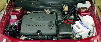
General view of the engine 10-12 series 16 valves
Not all motorists know the reasons for the loss of spark, much less methods for diagnosing and troubleshooting problems. So, it is worth identifying the main reasons, and then deciphering why exactly they become the cause. Finally, you need to consider ways to eliminate the defect. So, what reasons could cause the spark to disappear:
All the reasons have been found and it is worth moving on to the process of eliminating this malfunction.
Are you giving me a spark? Troubleshooting!
First of all, it’s worth noting that you don’t need to rush to check right away. As practice shows, there is a certain sequence of actions and malfunctions that could lead to loss of spark on a 16-valve engine.
Fuel pump
Fuel pump made by Bosch
Ignition is not the first reason for the ignition failure on a car. Before getting into the electrical part of the car, it’s worth delving into the mechanics, so to speak. Turn on the ignition and listen to see if the gasoline pump is working. If it is silent, then you need to check whether gasoline is entering the cylinders.
It is worth starting the diagnostic procedure by checking the fuses for serviceability. Of course, you can only view the one that is responsible for the fuel pump (in this case, when you turn on the ignition, the pump will not pump), but it is recommended to diagnose everything for integrity. If at least one fails, it must be replaced.
The fuses are located to the left of the steering wheel under the light mode switch
If the previous procedure did not help, then we turn directly to the pump itself. For diagnostics, you will have to remove the entire module, which is located under the rear sofa, and disassemble it.
Spark plug
Location of spark plugs on the engine
The candle becomes the second boundary, which may cause the spark to disappear. We unscrew the elements and carry out visual diagnostics. If everything is clean and beautiful outside, then you need to measure the resistance and check the gap. Of course, you can check the performance of a spark plug on a special spark plug stand, but not everyone has one in their garage. Therefore, we do everything the old fashioned way.
When performing this operation, you should be extremely careful, since the voltage that enters the spark can be fatal. Thus, we check all the spark plugs for the presence of a spark.
How to check the ignition module?
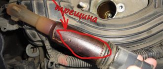
- First of all, we carefully inspect the module body. There should be no chips, burns or cracks on its surface. A module with a damaged casing is replaced without any hassle.
- If the spark is unstable only on cylinders 1-4 or 2-3, one of the module coils is probably damaged. In any case, we will conduct a comprehensive check of the device. For this we will need a regular multimeter.
Diagnostic procedure
The diagnostic procedure can be as follows:
- Disconnect the connector with signal wires from the module.
- Turn on the ignition and check the voltage at terminal 15 (central) of the control wire block. The rated voltage is 12 V. A drop or absence of voltage when the battery is charged indicates that the engine control unit does not supply power to the module. This means the reason lies in the ECU.
- We remove the high-voltage wires, unscrew the module mounting bots and remove it.
- We check the resistance of the primary windings of the coils - put the multimeter in resistance measurement mode and take readings from the rightmost and central terminals, then from the leftmost and central terminals. The nominal resistance of the primary windings is approximately 0.5 Ohm.
We measure the resistance of the secondary windings between terminals 1-4 and 2-3 high-voltage wires. Nominal value: 5.4 kOhm. If the readings do not correspond to the nominal value, the coil is not working correctly.
Check the module for a short circuit. To do this, install one tester probe on the central pin 15, the second on the metal body. The device should show the absence of a short circuit (one or infinity). Otherwise, one of the coils has shorted to the housing.
Errors
A module malfunction can also be determined using an error scanner. Error codes associated with the module are:
- R-3000, R-3001, R-3002, R-3003 and R-3004 - gaps in sparking, the module itself, spark plugs, high-voltage wires or the ECU may be to blame;
- R-0351 - the coil of cylinders 1-4 does not work;
- R-0352 - the coil of 2-3 cylinders does not work.
The scanner readings do not yet indicate problems with the module itself.
It is possible that the spark plugs are not working or the high-voltage wires are broken, but if we initially diagnosed them, then the fault lies entirely with the ignition module. In this case, we can repair it ourselves, or buy a new one, which is faster, easier and guarantees uninterrupted operation of the ignition system. Good luck to everyone, strong spark and good roads!
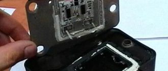
Repair
So, for the VAZ 2110 the most common problem is the disappearance of voltage on cylinders 2 and 3. After some time, the engine starts working normally again if you press the rear plate of the module.
You should not put up with such a situation; it is better to immediately check the functionality of the unit, restore or replace it completely.
Removing the module
The procedure is quite simple.
Now let's move directly to working with the module:
Carrying out such a repair of the ignition module on a VAZ 2110 with your own hands will not be difficult. But be careful, act carefully and consistently. Pay special attention to the soldering process.
If the cause of the malfunction lies elsewhere, then there is a high probability that it is better to simply replace the VAZ 2110 8-valve ignition module with a new one. The search may drag on without yielding results. Replacing the element will completely solve the current problem.
Ignition VAZ 2110 injector, diagram, spark plugs, ignition module VAZ-2110
The ignition of the VAZ 2110 injector is fundamentally different from the carburetor versions. Firstly, the ignition system of the injection “ten” does not have a distributor on the camshaft shaft and the main ignition coil, which are typical for all carburetor cars. In the injection models VAZ 2110, 2111, 2112, the ignition system is built without the use of moving elements.
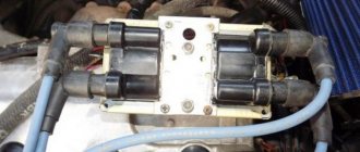
A feature of the VAZ 2110 injector ignition is the absence of advance angle adjustments; in addition, the “tens” injection ignition does not require any maintenance. The main element of the entire circuit is the ignition module , see the photo of the module at the beginning of our article. The module consists of a pair of ignition coils and electronics that control the distribution of high energy to the spark plugs. In turn, the controller sends commands to the VAZ 2110 injector ignition module . The entire ignition circuit is shown below in our image.
The ignition diagram of the VAZ-2110 injection engine shows the following elements -
- 1 - battery
- 2 - ignition switch
- 3 - ignition relay
- 4 - spark plugs
- 5 - ignition module
- 6 - controller
- 7 - crankshaft position sensor
- 8 - master disk
- A - matching device
The injector spark plugs on the “ten” for an 8-valve engine and for a 16-valve engine are different in design. For 8-valve injectors, spark plugs of the A17DVRM , for 16-valve power units these are spark plugs AU17DVRM . The latter have a more compact size and are unscrewed with a 16-valve wrench. In the 8-valve cylinder head, the spark plugs are installed in the same way as on the carburetor versions of the engine, but in the 16-valve cylinder head, the spark plugs are recessed vertically into the wells of the cylinder head. The normal gap between the electrodes of these spark plugs is 1.0-1.15 mm.
Sparking in the 2110 injection engine occurs in two cylinders at once. In this case, in one cylinder the spark ignites the working mixture on the compression stroke, and on the second cylinder the spark appears on the exhaust stroke and does not in any way affect the operation of the engine, that is, this is the so-called “idle spark”. Thus, sparking occurs in pairs, which facilitates the entire operation of the power unit. For this purpose, the ignition module contains two high-voltage coils with a constant current direction. The spark appears alternately in cylinders 1-4 and 2-3.
Another important element of the VAZ-2110 ignition is the controller. It is the ignition controller that gives the command to the module that it is time to direct current to certain spark plugs. The controller receives information from the crankshaft position sensors, mass air flow sensor, crankshaft speed and the presence of detonation. Even information about the coolant temperature is used. After processing all the information from the sensors and calculating the sequence of operation of the coils in the module, the controller sends a signal to the module, and from it current flows to the spark plugs. Thanks to this ignition system, the VAZ-2110 injection engine operates stably and reliably.
- VAZ 2110 injector engine, diagram and principles of operation of the “tens” injection engine
- VAZ 2110 engine, photo, device, characteristics of the VAZ 2110 engine injector, carburetor
- VAZ 2110 injector 16 valves, engine characteristics, timing device
Fuse and relay box
The VAZ-2111 relay and fuse mounting block is located on the left side of the steering column in the instrument panel. To access the unit, press the latch switch and lower the unit down.
K1 - lamp health monitoring relay;
K2 - windshield wiper relay;
KZ - relay-interrupter for direction indicators and hazard warning lights;
K4 - headlight low beam relay;
K5 - headlight high beam relay;
K6 - additional relay VAZ-2111;
K7 — relay for turning on the heated rear window;
K8 - rear fog lamp relay;
F1-F20 - fuses
| Number | Current, A | Description of fuses |
| F1 | 5 | License plate lamps. Instrument lighting lamps. Side light indicator lamp. Trunk light. Left side marker lamps |
| F2 | 7,5 | Left headlight (low beam) |
| F3 | 10 | Left headlight (high beam) |
| F4 | 10 | Right fog lamp |
| F5 | 30 | Door window motors |
| F6 | 15 | Portable lamp (socket) VAZ2111 |
| F7 | 20 | Engine cooling fan electric motor. Sound signal |
| F8 | 20 | Rear window heating element. Relay (contacts) for turning on the heated rear window |
| F9 | 20 | Recirculation valve*. Windshield and headlight cleaners and washers (wiper protection). Relay (coil) for turning on the rear window heating |
| F10 | 20 | Spare |
| F11 | 5 | Starboard side marker lamps |
| F12 | 7,5 | Right headlight (low beam) |
| F13 | 10 | Right headlight (high beam). High beam warning lamp |
| F14 | 10 | Left fog lamp |
| F15 | 20 | Electrically heated seats. Trunk lock lock |
| F16 | 10 | Relay-breaker for direction indicators and hazard warning lights (in hazard warning mode). Hazard warning lamp |
| F17 | 7,5 | Interior lighting lamp. Individual backlight lamp. Ignition switch illumination lamp. Brake light bulbs. Clock (or trip computer) |
| F18 | 25 | Glove box lighting lamp. Heater controller (heater fuse). Cigarette lighter fuse for VAZ 2110, VAZ 2111, VAZ 2112. |
| F19 | 10 | Locking door locks. Relay for monitoring the health of brake light lamps and side lights. Direction indicators with warning lamps. Reversing lamps. Generator excitation winding. On-board control system display unit*. Instrument cluster. Clock (or trip computer) |
| F20 | 7,5 | Rear fog lamps |
A fog lamp fuse is installed in the niche of the instrument panel behind the mounting block. The central locking fuse is located behind the fuse box in a plastic box. And additional relays and fuses (all 15 A) are located in the cabin on the right side of the instrument panel behind the side trim attached with two screws.
- 1 — ignition module, controller;
- 2 — canister purge valve, vehicle speed sensor, oxygen concentration sensor (heating), air flow sensor VAZ-2111;
- 3 - fuel pump relay, fuel pump fuse, injectors.
- 4 — electric fan relay;
- 5 - fuel pump relay,
- 6 - main relay (ignition relay).
Relay and fuse box diagram
This is a schematic diagram of the VAZ 2111 relay and fuse mounting block. The outer number in the wire tip designation is the block number, and the inner number is the conventional number of the plug.
| Block | № | Color | Electrical circuits |
| Ш1 | 1 | ZhCh | fog lamp (left) |
| 2 | GP | trunk lock motor, heated seats | |
| 3 | R | door lock relay | |
| 4 | ABOUT | power window relay | |
| 5 | ZhP | fog light relay | |
| 6 | AND | fog lamp (right) | |
| 7 | MS | power window relay | |
| 8 | — | reserve | |
| Ш2 | 1 | — | reserve |
| 2 | — | reserve | |
| 3 | — | reserve | |
| 4 | H | weight " - " | |
| 5 | ZhP | size (left rear) | |
| 6 | Warhead | outdoor light switch | |
| 7 | — | reserve | |
| 8 | ZhCh | license plate lamps, off instrument lighting | |
| 9 | KP | size (right rear) | |
| 10 | TO | size (right) | |
| 11 | ZhG | email windshield wiper motor, windshield wiper and washer switch. | |
| 12 | Z | outdoor light switch | |
| 13 | ABOUT | fog light switch | |
| 14 | Emergency | hazard switch | |
| 15 | — | reserve | |
| 16 | GP | Ignition switch (terminal 15), steering column switch | |
| 17 | R | windshield wiper and washer switch | |
| 18 | JV | steering column headlight switch | |
| 19 | — | reserve | |
| 20 | — | reserve | |
| 21 | AND | size (left) | |
| Ш3 | 1 | midrange | low beam (left headlight) |
| 2 | — | reserve | |
| 3 | WITH | low beam (right headlight) | |
| 4 | R | generator (cl. 30) | |
| 5 | TO | generator (cl. 30) | |
| 6 | TO | generator (cl. 30) 2111 | |
| Ш4 | 1 | PZ | on-board display system |
| 2 | GO | hazard switch | |
| 3 | IF | hazard switch | |
| 4 | H | weight " - " | |
| 5 | PG | portable lamp plug | |
| 6 | Salary | heated rear window switch, heated rear window lamp | |
| 7 | — | reserve | |
| 8 | — | reserve | |
| 9 | — | reserve | |
| 10 | ZhZ | steering column washer and windshield wiper switch | |
| 11 | B | email windshield wiper motor | |
| 12 | BW | steering column washer and windshield wiper switch | |
| 13 | GB | steering column switch, ignition switch lamp | |
| 14 | BP | brake lights, clock, interior lamp | |
| 15 | P | brake lights | |
| 16 | RP | off brake lights | |
| 17 | ABOUT | generator (cl. 30) VAZ-2111 | |
| Ш5 | 1 | AF | high beam (left lamp) |
| 2 | JV | rear window heating element | |
| 3 | G | heater controller, glove compartment lamp | |
| 4 | Z | high beam (right lamp) | |
| 5 | ZhG | Windshield wiper motor, SAUO recirculation valve | |
| 6 | PB | email cooling fan, beep |
To locate the faulty fuse, use the table of circuits protected by fuses. Before this, of course, you need to find the cause of the blown fuse, eliminate it, and only then install a new one. The table shows the circuits that each fuse protects, but on each model some of them may not be installed due to the lack of certain devices (for example, power windows, lock drives and other units).
Source