The head optics of the Lada Priora received daytime running lights (DRL) only after restyling at the end of 2013. On pre-restyling cars, the DRL function is performed by the low beam, which has to be turned on manually each time. Do you know how, with a simple modification, you can turn on the low beam automatically (it will light up when the ignition is turned on)?
The meaning of revision
: The function of the middle position (dimensions) of the lighting control module (LCM) will change. The low/high beams will light up automatically when the ignition is turned on and go out when turned off (the headlights do not light up). The only drawback of this connection is that you cannot turn on the dimensions with the engine running.
- Remove the ICC. First remove the fuse box cover, then remove the screw securing the MCU.
- Disconnect the connector with wires from the MUS.
- Swap the 4 wires in the block (green with pink and white-black with blue-black). To pull out the contacts (pins), you should press the antennae on both sides (it is convenient to use a hair clip).
Thus, rearranging the wires in the connector changes the switches. In other words, we close the same contacts, but in a different switch position.
Let us remind you that if you install DRLs yourself, you can use this connection diagram.
Nobody argues with the fact that running lights significantly increase road safety as they did a few years ago. In terms of providing this option, owners of foreign cars are in a better position. But what about comrades who are deprived of such an opportunity? It turns out that there are options, but subject to certain rules relating to the legal and technical aspects of the issue.
Place of the switch in the light switching circuit
On cars with manual transmission, voltage to the lamps when reversing is supplied through a limit switch (the so-called frog), which is screwed directly into the gearbox housing. When reverse gear is engaged, the switch button is pressed inside the gearbox. The contacts inside the “frog” bridge, and current begins to flow to the lamps.
On the circuit diagram for turning on the reversing lights, we can see that on the VAZ 1118 Kalina, the current from the battery through the ignition switch (No. 2) is supplied to fuse F1. Passing through the fuse that protects the switching circuit, “+” goes to the limit switch (No. 10). The contacts are in a normally open state and close only when reverse gear is engaged. Thus, current begins to flow to the light bulbs. The second contact of the lamps is connected to the “–” battery through the common ground contact of the lamps.
On cars with automatic transmission, the role of the limit switch lies with the selector position sensor. Information about changing the location of the gearshift knob is transmitted to the engine ECU, the light control unit.
How to check the "frog"
- Remove the headlight switch chip.
- Turn on the ignition.
- Using a small piece of wire, connect the contacts of the reverse gear sensor connector to each other.
If the reverse lights are on, then the problem is in the “frog”. Some drivers disassemble the switches, clean the contacts, after which the device continues to work properly. It is up to you to judge the appropriateness of such measures. But keep in mind that on many cars (including VAZ models) the limit switch is located below the oil level in the gearbox. We recommend simply replacing the power sensor. To minimize oil loss, jack up the car on the side where the end switch is installed.
On some cars, the reversing lights do not light up due to incomplete activation of the limit switch. The problem can be solved by installing a thinner washer under the “frog”. To make sure that the switch is working, check with a multimeter in ohmmeter mode whether the contacts close when you press the button.
Checking the circuit
The essence of diagnosing the reason why the reverse lights do not work comes down to identifying the section of the circuit where the voltage is lost. To do this, you can use a regular control light. Continuity testing is done with an ohmmeter, so you need to know how to use a multimeter.
You can start checking directly from the limit switch connector. Turn on the ignition. Connect one contact of the control light to an unpainted metal part in contact with the body, and the second to the “+” connector.
- If power comes in, check the reverse sensor.
- If after installing the “jumper” in the connector the lights do not light up, then the problem is in the section of the wire circuit going from the connector to the lights. Ring the wire to the point where it divides into light bulbs on the left and right sides. Most likely, the reason is the break.
To find the pinout of connectors, light contacts, and wire colors, be sure to study the electrical diagram of your model and vehicle configuration.
DRL with lenses
Philips with COB and lenses
- model Philips DayLightGuide 12825WLEDX1
- 7 W each;
- luminous flux 875 lm, 125 lumens per watt.
- color temperature 6000K, light slightly bluish, cold;
- service life 5000, not enough;
- power supply 12V;
- dimming, at night the brightness is reduced (muted) and perform a decorative function;
- Philips Luxeon LEDs, probably COB;
- optics in the form of one stretched lens;
- the control unit is compatible with hybrid and electric cars, and the Start-Stop system;
- aluminium case;
- dimensions: 165 x 35 x 23 mm;
- Price about 6,000 rubles.
Probably COB technology is used, when many crystals are placed on one substrate and one long LED in the form of a line is obtained.
The main features of good DRL using lenses
- It is obligatory to have cooling fins at the back, although the technology is used by COB, but heating has not gone away. If there are no ribs, then there is nothing to cool.
- Since the KOB line emits light over the entire surface, optics, such as this Philips, are required. The lens is made in the form of a half circle and runs along the entire body. The COB beam angle is 120 degrees, if there is no good lens, the light will go to the sides.
- Energy consumption cannot be determined visually, or even guessed. Here you have to rely on the information provided by the store.
- The COB power must be at least 10 W, and the luminous flux must be at least 1000 lm.
Philips reviews are not all good; many complain about the build quality. Due to poor sealing, they begin to fog up and condensation appears, although the stated standard of protection from moisture, dust, and salt. Power supply and control units fail. All this is written on Philips’s own website.
Possible wiring faults
What malfunctions in the operation of the on-board network may a car owner encounter:
- The device itself does not work. For example, the rear window heating system or the electric side mirror controller refuses to function. There is a possibility that the reason lies in the device itself or the fuse that is responsible for its operation.
- Short circuit in the electrical network. As stated above, a short circuit problem usually manifests itself as a result of insulation failure in one area or another. To prevent this, wires should be laid in places where there are no moving elements.
- Broken wiring. This malfunction is typical for many Russian-made cars. To prevent a breakdown, consider the recommendations described in the paragraph above.
- Failure of the safety element. If you notice that malfunctions have begun to appear in the operation of certain devices, then first you should open the mounting block and check the integrity of the fuse itself. There is a possibility that this is where the problem lies. Typically, safety devices break due to too high voltage in the on-board network. If the reason really lies in overvoltage, then first you need to eliminate the problem itself, and only then change the fuses.
- Lack of contact. In this case, a section of the circuit may be intact, but there will be no contact. Most likely, in this case, the problem lies in the fact that the wire has come off a little or the contact at its end has oxidized. In this case, the contact is cleaned using a brush or sandpaper, after which the wire is reconnected.
Description and location of indicators and instruments on the panel
In accordance with the diagram, the description and designation of the icons on the new combination in Priora is as follows:
- Tachometer. This controller is used to display the number of revolutions of the power unit (crankshaft) per minute. The red zone of the sensor indicates speeds that it is better not to reach and which should not be exceeded in order to avoid damage to the crankshaft.
- Left turn indicator. When the turn signal is turned on, this symbol flashes, and the sound signal also turns on when it is on.
- One of the main sensors - the speedometer - allows you to determine the speed at which the car is moving.
- Right turn signal. Both left and right turn signals are activated when the hazard lights are turned on and light up synchronously.
- This sensor on the Lada Priora dashboard shows the temperature of the engine warming up or antifreeze in the cooling system. The controller arrow should not rise to the specified limit, otherwise this may indicate overheating of the power unit. In case of such a problem, you need to immediately turn off the engine and allow it to cool, and also identify the cause of the problem.
- In accordance with the pinout, this sensor on the dashboard with or without navigation determines the volume of the fuel level in the tank. It is advisable not to allow the indicator arrow to move towards the red zone, this will indicate the need to refuel the car. In any case, sediment collects at the bottom of the tank, no matter how high-quality fuel you use. When the fuel pump tries to produce this fuel, it clogs faster and may fail.
- This indicator indicates that the fuel pump has started pumping reserve fuel; the icon is shaped like a column. If it appears, then the tank needs to be refilled urgently.
- A button used to reset the daily mileage information.
- Light signaling. When this function is activated, the left and right turn signals on the dashboard will flash.
- Indicator light indicating that the EUR is not working. The icon always appears when the ignition is activated, at this time the instrumentation and amplifier are tested, when the engine is started, the indicator will disappear.
- The high beam activation indicator lights up blue.
- The next icon on the Priora control panel is the activation of the parking brake, which appears when the driver lifts the lever. If the handbrake is raised, the icon will light up even when the engine is running.
- The icon for activating the headlights, in particular, we are talking about side lights or low beams. The indicator lights up green.
- Functional airbag indicator light. If the indicator continues to light after starting the engine, then most likely there are problems with the security system. First of all, you need to check the condition of the sensors.
- Symbol of critical engine oil pressure. The indicator always lights up when testing the device, but if it appears while driving, the car owner should check the lubrication system. First of all, you need to make sure that the volume of oil in the engine corresponds to the norm - if the volume is insufficient, the fluid must be added. The reason for the appearance of the lamp may also be due to a failure of the pressure sensor or its poor contact with the on-board network.
- The immobilizer symbol lights up orange. This icon is intended to alert the driver that the anti-theft system has been activated.
- A display showing the car's mileage over the past 24 hours. Also in the middle of the screen are indicators of the main options.
- The seat belts not fastened icon, lights up red, always lights up during self-testing of the shield. If you are not using seat belts, an audible signal should also sound.
- Battery icon. It also always appears when the ignition is turned on, so the dashboard tests all indicators. If the icon continues to light after starting the engine, this indicates that there is something wrong with the battery. The reason for its appearance may be related to either the battery being discharged due to the inoperability of the battery itself (shedding of the plates, boiling off of the electrolyte, etc.), or to problems with the operation of the generator. In particular, we are talking about a worn assembly belt or its damage; sometimes the reason lies in the wear of the brushes.
- Brake system condition controller. This indicator lights red and indicates a malfunction in the above system. There may be several reasons; the fault can only be determined through diagnostics.
- Symbol of problems with the electronic brake force distribution system. It should not light up when the power unit is running.
- Airbag deactivation or inoperability symbol. In this case we mean the front airbags.
- If this symbol appears, then we can conclude that the ABS does not work or is not functioning correctly. It is necessary to carry out detailed diagnostics of the system to identify the malfunction. In some cases, the reason lies in a malfunctioning sensor.
- Check Engine is an indicator that appears if the control unit has detected problems with the operation of the power unit. Problems can be very different; it is unlikely that it will be possible to determine the problem at random, so most likely you will need computer diagnostics (the author of the video is the Automotive Diagnostics channel).
New Lada: Article in Autoreview about corrosion resistance of paint. Autoforum main
Pinout of the instrument panel VAZ 2170 Priora
The layout of the instrument panel is made in a simplified version to facilitate the replacement and installation of replacement parts. The decoding of the wiring connections at the factory terminals looks like this:
- 1 – EUR;
- 2 – emergency signal control;
- 3 – oil pressure sensor;
- 4 – indicator light for turning on the hand brake;
- 5 – immobilizer control unit;
- 6 – control unit for airbags;
- 7 – external lighting of the car;
- 8-9 – direction indicators;
- 10 – control of the combustible mixture injection system;
- 11 – disabling the front passenger SB;
- 12 – indication of seat belt buckles;
- 13 – operation of the brake system;
- 14 – reset button of the steering column switch;
- 15 – indication of the expansion tank of the brake system;
- 16 – ABS control unit;
- 17 – headlight high beam position switch;
- 18 – dashboard lighting;
- 19 – mass;
- 20 – receiving power from the battery terminal;
- 21 – ignition switch connector;
- 22 – fuel consumption sensor;
- 23-24 – BC mode switch;
- 25-26 – temperature sensor “overboard”;
- 27 – remaining fuel in the tank;
- 28 – speedometer;
- 29 – antifreeze temperature indication;
- 30 – tachometer;
- 31 – diagnostic terminal;
- 32 – power supply from generator (L).
Checking and adjusting the operation of the mechanism
Regular preventative examinations will help you avoid sudden breakdowns. According to the manufacturer's recommendations, these are carried out at least once every 3 months. Unscheduled, you will need to look under the hood if the Priora's lights have become dim. Regardless of the reason, a key at “6” is required for operation.
The car owner must check the air pressure in the tires. Even a slight deviation from the norm will negatively affect the efficiency of lighting devices. After this, the vehicle is installed on the most level surface of the garage. LADA Priora is placed at a distance of 5 m from a smooth wall. The further procedure is as follows:
Direct adjustment is carried out in the vertical and horizontal plane. In order to adjust the position of the light spot as accurately as possible, you should first turn on the low beam. The setting is made for each headlight separately. In order to comply with technical recommendations, when adjusting one of the headlights, the second one must be covered with material that does not transmit light.
If you don’t have one at hand, then you just need to turn off the power. Only after this does the transition to high beam adjustment take place. The lighting adjustment process ends with a mandatory check. A vehicle rolls out of a garage onto the street at night.
The high beam turns on, and then the low beam. A visual inspection is carried out. If asymmetry of the light spots is noted, then the adjustment is made again. In some cases it is necessary to visit a service station.
Additional mounting block Priora
- F1 (15 A) – main relay and starter interlock circuit fuse;
- F2 (7.5 A) – fuse for the power supply circuit of the ECU (controller);
- F3 (15 A) – Priora fuel pump fuse;
- K1 – main relay;
- K2 is the place where the Priora fuel pump relay is located.
Attention! The relay and fuse diagram may differ depending on the configuration and production date of the vehicle. Current diagrams of the mounting block are presented in the operating manual for the date of manufacture of the vehicle (download from
site).
Let us remind you that on our website you can find detailed instructions for repairing the Lada Priora with your own hands.
Priora crash test. mannequins are fastened
Taking into account the requirements of the Euro CEP program, the car received an impact weighing 950 kg on the B pillar on the front driver's side at a speed of 54 km/h.
When watching the Lada Priora crash test video, you will notice that the car was thrown as much as 5 meters from its original position and turned around its center of mass. But even in this situation, the locks were not damaged, the doors remained closed, and the side panel wrinkled by only 0.33 meters.
From this result we can conclude that the Priora’s body can withstand loads of this kind very well. The Priora crash test allows the car to receive 12 points out of 16.
After crash testing the car, all dummies were in their places, but a slight displacement of the front passenger was noted. All security latches came off easily.
After analyzing the data from the sensors, partially encouraging results were obtained:
— Head impacts on the side posts did not threaten even a minimal concussion. — The “driver’s” chest fell into the red zone.
In the area of the ribs, the load was 39 mm with a limiting deformation value of 43 mm. In the pelvic region, the sensors were compressed with a force of 5.2 kN, with a deformation threshold of 6 kN.
The Lada Priora crash test recorded that when simulating a side impact, the total load on the abdominal part of the body was slightly higher than the safe 100 kg/force. Taken together, this made it possible to evaluate the protective ability of the Priora body at 9 points out of a possible 16.
Standard DRLs (daytime running lights) on Priora - article number and price
Standard lighting devices are located inside the Priora headlights:
left – 2170-03711011-00, price – 6000-7000 rubles; right - 2170-03711010-00, price - 6000-7000 rubles.
Standard lighting devices are located in the same “cell” with the main beam. To “activate” them, a DRL-30 relay is installed on the Priora, costing about 600 rubles. The whole secret is that relay “30” is installed instead of the standard high beam relay.
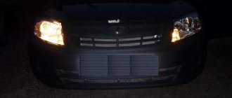
Thanks to this modernization, the daytime running lights light up when the driver turns on the ignition with the key and then releases the handbrake. These two actions should activate the lights - a new “preset” appears thanks to 30 relays. In this case, the headlights do not light up simultaneously with the DRLs. This upgrade for pre-restyling headlights will make them as functional as the restyled ones.
practical guide
1. Turn off the exterior lighting and remove the headlight cover!
2. Remove the side light lamp socket from the reflector.
3. Remove the faulty lamp from the socket.
4. Insert the new lamp into the socket and install the socket into the reflector.
5. Install the cover on the headlight unit and secure it with a spring clip.
The operation is shown on the left headlamp, access to the cover of which is made difficult by the battery.
1. We prepare the car for work. Turn off the outside lighting.
To replace the lamps in the left headlight unit, you must remove the battery.
2. Release and remove the spring retainer securing the headlight cover.
3. Remove the cover and remove it from the engine compartment.
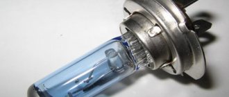
Do not touch the bulbs of halogen lamps with your fingers. Fatty fingerprints left on the lamp bulb will shorten its service life several times. Work in clean cotton gloves without rubber coating. If your fingers accidentally touch the lamp bulb, wipe the bulb with a clean cloth moistened with alcohol.
4. Release the spring clamp securing the low beam headlight lamp.
5. Remove the faulty low beam headlight bulb from the reflector.
6. Remove the wire lugs from the lamp terminals.
7. Install a new reverse sequence lamp.
8. We replace the high beam lamp in the same way.
To adjust the headlight you will need:
— a flat horizontal area (preferably near the wall of a house, a fence or at a gate);
— tape measure 5 m long;
— a sheet of cardboard (to cover the headlight when adjusting).
We carry out the work with an assistant.
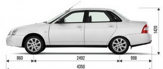
Screen marking diagram for adjusting the light of the headlights: A - vertical line indicating the location of the center of the low beam lamp of the left headlight; B - vertical line indicating the location of the low beam lamp of the right headlight; B - horizontal line indicating the location of the low/high beam headlight lamps; G - line indicating the height of the rise of the horizontal border of the light beams; O - center line; l is the distance between the low beam lamps of the headlights; h - distance from the surface of the platform on which the car is installed to the center of the low beam headlights
It is advisable to carry out the adjustment in the dark. The vehicle must be in running order (fully fueled and without additional cargo). Since it is not easy to find a suitable surface as a screen, it is easier to use a 1x2 m plywood board with markings applied to it. In this case, it is necessary to prepare a stop or stand to install the shield vertically.
Installation
Replacing the old instrument panel without CAN with a dashboard with navigation without CAN (2170-3801010-50) is carried out without modifications. We remove the old panel and install a new one in its place, insert the connector with wires, connect the antenna (we fix it on the roof) and, if necessary, change the right steering column switch.
If the old instrument cluster without navigation, but with CAN, and instead of it it is planned to install a new dashboard with navigation with CAN (2170-3801010-60), then you need to rearrange contacts 10-11 to 28-29 (if after connecting it still does not work, change 28 and 29 places). See instrument cluster pinout.
After installing the new instrument panel, the mileage will be reset to zero.
Navigation in the instrument panel runs on Windows CE 6.0 along with Navitel software. It is possible to update the software and download navigation maps from a USB card via a special USB input. Operating the car will become much more pleasant, the only drawback is the high price.
Have you ever had to install a new type of instrument panel with navigation on a Priora or Kalina? What difficulties did you encounter during this revision? Let us remind you that on the Lada.online website you can find other instructions on tuning and modifying Lada Priora or Kalina cars, for example, how to adjust the electronic gas pedal or improve the brakes without modifications.
Keywords: instrument panel Lada Priora | dashboard of Lada Kalina | torpedo Lada Priora | Lada Kalina torpedo
Found an error? Select it and press Ctrl Enter..
When Chevrolet Niva will receive restyling, new details
Photos of the anniversary Lada 4x4 and distinctive features
How to close the Lada Vesta engine radiator in winter
Diagnostics of Lada electric power steering without a scanner
Removing the screen
To continue disassembling the instrument panel in the Priora for tuning with your own hands, remove the screen. It rests on rubber conductors, so it is also easy to remove. Turn the panel over and unscrew the remaining bolts. We also take out light bulbs that are no longer needed.
Using pliers, release the clamps and take out the screen. Under the screen there is another light guide - a bright light green color; it must be removed.
The panel is almost disassembled, all that remains is to separate the main white part from the green microcircuit. Thus, we have disassembled the entire dashboard and can continue tuning the Priora instrument panel.
How to disarm the electrical package unit of LADA PRIORA
What to do if Priora is not removed from the standard alarm!
The hazard warning light blinks, the car does not respond to the ignition key buttons. As a rule, several units are involved here that are synchronized with each other.
- Ignition
- Radio channel module (Located in the driver's door)
- Electrical package block (Comfort block)
- Engine ECU
New blocks come with non-activated codes inside and can be installed on any car without problems, but once you register (train) the keys, a special code is written into all these blocks, which is synchronized with each other and serves as a standard alarm system. (Immobilizer) As soon as you turn the ignition key, within five seconds there is a poll between the key and the units, if the code matches everywhere, then the engine ECU gives permission to start, if the code of at least one device is not recognized, the engine ECU is blocked and the car does not start.
Training a working key is done using a special red training key. I will not describe the procedure for training keys; there is plenty of information on the Internet. In fact, the main key is a red training key; it stores a code that, after training, is written into the working key and other blocks.
I'll try to explain in more detail how it all works:
- The radio channel code that we use to open doors using the key's remote control buttons is written into the driver's door module, where the power window buttons are located. If you replace the comfort unit or engine ECU, the buttons on the key will still work.
- The IMMO (Immobilizer) code has a connection only with the ignition key, the electrical package unit and the ECU unit. If you disconnect the driver's door module, the car will still start.
How to determine whether the keys are trained or not:
- The IMMO lamp on the instrument panel goes out after 5 seconds - the keys are trained.
- The IMMO lamp goes out after 30 seconds - the keys are not trained. (The car will start with any blank)
Options for disabling IMMO:
Write an untrained eeprom dump to the engine ECU. All functions will remain working as normal, key buttons, etc., only the car will start with any blank.
If the vehicle cannot be disarmed using the remote control:
- Here the situation is a little more complicated, this is why this article was written. Suddenly, for some reason, the car remained on guard, the hazard lights blink, the car beeps, etc. Of course, you will open the car mechanically using the keyhole in the door, but at the same time constantly The hazard warning lights blink and the comfort functions do not work, and the car does not start. The reason could be a breakdown of the remote control key or the driver's door module. However, the electrical package unit remained armed.
- There are two ways to disarm the electrical package unit: 1) Install the driver's door module from another car and open it remotely from the key of the same car. In this way, you can disarm the comfort unit. 2) Disassemble the electrical package unit and use the programmer to clean the M95080 memory chip.
Comfort unit, disarming. This instruction applies only to unlocking the electrical package unit. If you need to unblock the engine starting, it is enough to write an unlearned eprom dump into the engine ECU.
We disassemble the block and find the memory chip eeprm M95080. It is enough to insert this chip into the programmer and completely clean it, or replace it with a new one if there is no programmer. When re-learning the keys, all the necessary data will be written into it again.
After cleaning the microcircuit, the electrical package unit will disarm.
A few more photos on the topic and video.
Pinout of the comfort block for connection on the table.
Electric package controller connection diagram.
How to disarm the Priora electrical package 2170-3763040
Repair and replacement of individual elements
Wear of headlight elements, physical damage or short circuit are only a small part of the reasons why the luminous flux is lost or noticeably weaker.
In this case, you need a “10” key and a Phillips screwdriver. To begin, carefully remove the negative terminal from the battery and the front bumper. Only after this LADA Priora is ready for work:
- release the lock;
- disconnect the bundle of wires;
- Unscrew the screw for the side mounting of the headlight on the Priora;
- remove 4 clips;
- Unscrew the housing fastening bolts.
To complete this task you will need an industrial hair dryer. It works at a distance of 2-4 cm from the surface of the headlight. The duration of thermal exposure is 30 seconds. After the industrial hair dryer is turned on, it is necessary to act in a circumferential manner on the entire surface of the top cover. The result of the work done will be melted sealant. It does not cause technical malfunctions, while allowing you to carefully remove the lighting element on the Priora.
Fuses and relays in Lada Priora, electrical diagrams
Lada Priora is another car in the line of new VAZ cars, which is gaining popularity among segments of the population
External similarities with the 10th model attract the attention of young people; the relatively low price is also a reason for purchase for most car enthusiasts. Along with the growth in popularity, the owners of this model are gaining experience in repair and maintenance, which is becoming more and more every year.
If your Priora has electrical problems, do not rush to get upset; first, check the fuses and relays in your Lada Priora. These are the ones that will be discussed in this article.
Other reasons
Sometimes the high or low beam fails due to the fact that the car owner thoughtlessly makes changes to the electrical circuits of his vehicle, without having a proper understanding of their operation. If such interference took place, then you should carefully analyze your actions and check what exactly was done wrong.
When none of the above recommendations helped fix the problem, it would be better to contact a car repair shop, since, most likely, attempts to search will lead to an even worse situation. In this case, you will subsequently need much more money to eliminate the fruits of your inept actions.
How to choose
Having decided to replace a relay or fuse in a Priora, take full responsibility for their selection and purchase. Under no circumstances should you buy cheap parts of unknown quality and origin.
It is better to give preference to original products produced by VAZ. As a last resort, buy relays or fuses from one of the well-known companies, such as Bosh, Hella or Tesla.
Replacing the sound signal on a Lada Vesta is a simple procedure that any owner should be able to perform. After all, driving without a properly working horn is a priori unsafe, and taking a car to a service station due to such a breakdown is an unreasonably large amount of time. However, replacement in the event of a malfunction is not the only need. Many people are simply not satisfied with the volume or tone of the sound signal, and they replace the standard Vesta components with alternative ones. Therefore, both of these paths need to be considered in more detail.
Circuit breakers
This is the second most common cause of low beam failure. If the left headlight does not light, then it is worth inspecting fuse F6.
Where is he located? It is located in a block hidden under the steering wheel. To get there, you need to remove the protective cover, which is held in place by three clips.
When the right light fixture does not function, look at fuse F7.
The protective devices mentioned above have the same rating - 7.5 amperes. The easiest way is to replace the damaged fuse with a working one. If one is not at hand, then as a temporary measure a “bug” is installed, that is, a jumper made of any suitable piece of copper or aluminum wire. In a pinch, even regular foil will do.
It is worth knowing that frequent blown fuses clearly indicate problems with the wiring. As a rule, a malfunction here often occurs due to the fact that the insulation of current-carrying elements is frayed. It is important to find the defective location and insulate it as soon as possible, since the occurrence of a short circuit leads to a fire in the vehicle.
The light in the trunk does not come on
Mikrik is located in the castle itself. You have to remove the door trim to get to it. Do a search - there was a thread with pictures of the trunk lock. But keep in mind that the light is turned on not by the microphone itself, but by the REC (rear electrical unit) based on a signal from the microphone.
I found a thread on the forum with photos of oxidized contacts of the trunk lock - I took my lock apart, the contacts there became like wire from oxidation and one even broke off, I had to “fix” it back.
After that, both problems disappeared: the light turns on properly, the alarm “by itself” does not work.
PS I bought a white LED light bulb in the trunk, inserted it, and it flickered like a strobe light. What could be the problem? The light bulb itself is in good working order, I checked it in the interior lamp.
Had the same problem. In addition to this, the alarm sometimes turned on by itself in the middle of the night.
I found a thread on the forum with photos of oxidized contacts of the trunk lock - I took my lock apart, the contacts there became like wire from oxidation and one even broke off, I had to “fix” it back.
After that, both problems disappeared: the light turns on properly, the alarm “by itself” does not work.
PS I bought a white LED light bulb in the trunk, inserted it, and it flickered like a strobe light. What could be the problem? The light bulb itself is in good working order, I checked it in the interior lamp.
Parallel to the LEDs, install a resistor with a resistance similar to that of a glowing incandescent lamp (5 W there? Then 12^2/5 = 29 Ohms.) The reducer is at least 5 W and ensure good heat dissipation - do not wrap it in anything, do not lean it against plastic. Let it be in the air in some kind of mesh frame.
The reason for all this is the transistor switches that light the lamps. Either the switch does not reach operating mode with such a meager collector current, or some circuit that analyzes the current and enters oscillation mode with such a meager current.
DIY DRL
Before installing daytime running lights on a Priora, you need to get them somewhere. There are two options: make the lights yourself or buy ready-made ones designed for Priora. Let's start with the first one. Since there is no special place for installing DRLs on Priors produced before 2013, we are not limited by the shape and size of DRL headlights.
From LED strip
Perhaps this is the simplest option for the Priora. To implement it you will need:
Since daytime running lights are not decorative lighting and must be clearly visible during daylight hours (this is their main purpose), the LED strip must be bright enough. Choose one that is assembled with LEDs of at least 0.5, and preferably 1.0 W. For example, LEDs 5630, 5730, 2835, 5050 have this power.
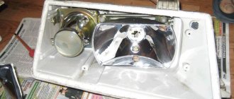
Before cutting the tape, you need to determine the desired length. To do this, remove the headlights from the priors and disassemble them to get to the decorative trim. The glass of the Priora headlights is mounted on a sealant, which can be softened using a technical hair dryer. If after warming up the glass cannot be removed, cut the still hot sealant with a utility knife.
Warming up the glass of Priora headlights with hair dryers
The most convenient location for the DRL on a Priora headlight is the lower edge of the trim. Measure its length: this is exactly or approximately this length that the pieces of the LED strip should be.
Installation location of the tape on the Priora headlight reflector
Now you can cut the tape, but you need to do this only in strictly defined places. These places are marked on the tape itself.
Places for possible cuts of the LED strip
Of course, because of this, you won’t get exactly the required length of the segments, which means you have two options:
- Make the segments shorter.
- Cut off more and fold the excess behind the trim.
I prefer the second one, since a segment that is too short will have low light output and is absolutely useless on the Prior as daytime running lights.
Cut it off? Now solder wires of different colors to the “+” and “-” contacts marked on the tape so as not to confuse the polarity of the connection. Then use glue or sealant to glue these sections into place. To check, connect your new daytime running lights to a battery or just a Krona battery. Do not mix up the polarity!
Checking DRLs from an LED strip (a uniformly glowing cluster strip was used)
All that remains is to assemble the headlights, placing the glass on the sealant, install them on the Priora and connect them correctly (see the “Connection to wiring” section).
Daytime running lights on the Priora from individual LEDs
If you don’t want to disassemble the headlights, then you can get by with little expense by installing daytime running lights in the Priora bumper, which can be easily drilled even with a wood drill or an ordinary brace. To implement this design, you will need powerful LEDs, which are popularly called “Eagle Eyes”. They do not have a specific purpose, but they are perfect for priors.
Eagle Eye LEDs
To provide the necessary brightness of daytime lights, you will need 6 LEDs. Installing them on the Priora is very simple. To do this, just drill holes of the appropriate diameter in the bumper and secure the LEDs in them in two groups using fastening nuts.
Connection points for standard alarm systems on Lada Priora
- Hood end (-) – white, black in the connector in the middle;
- Ignition (+) – orange in the connector in the middle;
- Button for opening the trunk lid (-) – black, white in a small connector;
- Luggage compartment end switch (-) – black, white in a small connector;
- Factory sound warning system - black, white on the safety panel. Owners of VAZ models change or improve the existing protection. Upgrading protection on a Priora is not difficult. To control the central locking, you need to cut the brown wire in the driver's door and connect according to the diagram.
Basic limit switches
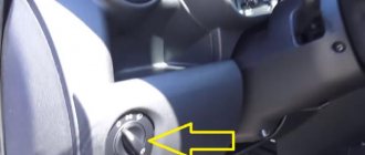
- Ignition – blue, black, located in the ignition switch area;
- Starter – red;
- Turns – blue and blue with black line;
- Ignition – orange;
- The hood tip is white with a black stripe;
- The generator is black with a brown line.
Other solutions for daytime lights on the Lada Priora
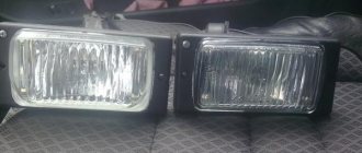
According to traffic regulations, the installation of additional equipment is not required, and instead of DRLs, you can use low beams, side lights or connected Priora fog lights. However, such solutions in practice are not the most effective for increasing vehicle visibility.
Disadvantages of neglecting special running lights:
- The side lights, which have a power of 5 W, are clearly visible in the dark. During the day they become almost completely discolored and are almost invisible.
- The low beam headlights make it possible to clearly identify the car on the road; it becomes truly distinguishable. But this option, when driving frequently with the headlights on during the daytime, leads to their rapid wear and excessive fuel consumption. It is necessary to ensure the simultaneous consumption of electricity for the dashboard and side lights. More than 0.4 liters of gasoline are required to travel 100 km in a Lada Priora car.
- It is not recommended to use high beam headlights as daytime running lights, both for the reasons stated for low beam and because of the risk of dazzling the drivers of cars moving opposite.
- Fog lights do not provide a good range of light and vehicle visibility is insufficient.
Fog lights can replace running lights in Lada Priora
Instrument cluster
Tuned control panel of a Priora car
First, let's look at the description and pinout designation of the icons of the new instrument panel on the Lada Priora car.
So, the shield includes the following elements:
- A tachometer device designed to demonstrate engine speed. Red arrows on the combination indicate speeds that are not recommended to be exceeded. Lada Priora allows you to accelerate the engine to six thousand revolutions.
- Pinout icons for light alarms or turn signals. A green arrow pointing to the left lights up on the dashboard when the left turn is engaged. It not only lights up, but also blinks, the same applies to the right turn signal. In addition to the fact that the icon turns on, at this moment the sound signal also works; its shield turns on along with the turn signal.
- The speedometer shows the speed level at which you are traveling.
- Refrigerant temperature level sensor in the system. If, as a result of any malfunctions, the coolant temperature increases to 115 degrees, an audible signal will tell the car owner about this. This will happen for five seconds until the temperature drops to 110 degrees. To prevent the engine from overheating, you should turn it off and get rid of the problem of antifreeze boiling.
- The designation of the arrow for the level of gasoline in the tank is known to everyone. If the arrow on the Lada Priora instrument cluster has approached the red zone, this indicates that the tank needs to be refilled as quickly as possible, since there are about five liters left in it. Please note that sediments present in the fuel collect at the bottom of the gas tank, so it is not recommended to use gasoline completely.
- A pinout icon indicating that the gasoline reserve is turned on; this symbol is made in the form of a gas station. When it lights up orange and stays on continuously, it means refueling is needed.
- There is a button on the speedometer designed to reset the daily mileage; when you press it, the daily mileage will be reset to zero.
- Alarm. When this function works, red icons are activated on the Lada Priora instrument cluster. The vehicle's parking lights begin to flash, indicating a breakdown.
- An icon indicating the operation of the electric power steering. When the ignition is turned on, this icon works and passes the test, but after the engine starts, the backlight disappears.
- Icon with blue highlight. On the Lada Priora combination diagram, when you turn on the high beam headlights, you will be able to see the corresponding icon with a blue backlight, but it will be practically invisible during the day.
- Handbrake icon that illuminates when the lever is activated. The backlight of this element lights up in red; it also disappears when the engine starts, after the test.
- Symbol for turning on external lighting, that is, side lights or low beam. The icon turns on with a green backlight.
- The symbol of working airbags on the Lada Priora combination diagram turns on for 3-4 seconds after turning on the ignition, during the test, it lights up in orange.
- Engine fluid pressure emergency icon. There is also this icon on the navigation diagram for the driver; it always lights up in red when the ignition is on and goes out after the engine starts, that is, the test. The driver must always use the navigation panel of the Lada Priora and monitor the operation of this indicator. If it does not light up when igniting, this may indicate a sensor malfunction. If the fluid pressure level is below the required level, an audible signal will tell the driver about this within five seconds. It is not recommended to operate the car when the fluid level is low, as this will harm the engine.
- Immobilizer icon. On the navigation diagram you can see a symbol with orange backlight - the immobilizer icon. The element demonstrates to the driver whether the Lada Priora vehicle protection system is turned on or not.
- The computer is another symbol that shows the full mileage of the Lada Priora per day, with indicators of the main functions located in the middle.
- The seat belts disconnected symbol lights up red during the test; if the seat belts are not fastened, the system will sound a corresponding buzzer.
- Battery symbol. Another indicator that is tested when the ignition is turned on is the battery symbol. When you turn the key, it passes the test and lights up, the indicator goes out after the engine starts. It should be noted that the operation of this component of the Lada Priora instrument cluster must always be monitored. If it does not turn on, then there is a possibility that the battery is not ready for use or the sensor has failed. If the indicator functions while the engine is running, this may indicate a low battery charge. There is also a possibility that the timing belt is loose or broken, or the generator is not working correctly (the brushes are worn out).
- The brake system status regulator is also located on the Priora dashboard. This symbol on the combination lights up in red when the ignition is on, like other sensors, it stops working after the engine starts. If the brake system does not pass the test, then using the Lada Priora is not recommended.
- The Check Engine regulator on the Lada Priora combination indicates the condition of the engine. When the ignition is turned on, it passes the test and turns off when the engine starts. If the symbol continues to light while the engine is running, this indicates a malfunction of the unit; it is recommended to carry out computer diagnostics of the engine. This is the only way to obtain the most accurate data about possible breakdowns that need to be eliminated in the near future.
- The ABS system icon lights up continuously when it fails.
- Airbag disabled icon. The driver's navigation control panel also has this icon, in particular those located on the front passenger seat.
- Symbol of failure of the electronic brake force distribution system (video author - Automotive Diagnostics).
New Lada: VAZ 2108 Driving Simulator Game - Online
How to disarm the electrical package unit of LADA PRIORA
What to do if Priora is not removed from the standard alarm!
The hazard warning light blinks, the car does not respond to the ignition key buttons. As a rule, several units are involved here that are synchronized with each other.
- Ignition
- Radio channel module (Located in the driver's door)
- Electrical package block (Comfort block)
- Engine ECU
New blocks come with non-activated codes inside and can be installed on any car without problems, but once you register (train) the keys, a special code is written into all these blocks, which is synchronized with each other and serves as a standard alarm system. (Immobilizer) As soon as you turn the ignition key, within five seconds there is a poll between the key and the units, if the code matches everywhere, then the engine ECU gives permission to start, if the code of at least one device is not recognized, the engine ECU is blocked and the car does not start.
Training a working key is done using a special red training key. I will not describe the procedure for training keys; there is plenty of information on the Internet. In fact, the main key is a red training key; it stores a code that, after training, is written into the working key and other blocks.
I'll try to explain in more detail how it all works:
- The radio channel code that we use to open doors using the key's remote control buttons is written into the driver's door module, where the power window buttons are located. If you replace the comfort unit or engine ECU, the buttons on the key will still work.
- The IMMO (Immobilizer) code has a connection only with the ignition key, the electrical package unit and the ECU unit. If you disconnect the driver's door module, the car will still start.