The ignition system (IS) in any car is one of the most important in the car, since it is its optimal operation that ensures the engine starts. Malfunctions of one of the SZ elements can lead to malfunctions in the operation of the power unit. What is the ignition circuit of the VAZ 2109 carburetor, what problems can occur in its operation and how to set up the ignition yourself? Find out from this material.
How to check high-voltage wires of a VAZ 2110
how to check the high-voltage wires of the ignition system.
Diagnosis of misfires on VAZ cars.
High-voltage wires of engine 2112 (1.5i 16v) - check and replacement.
Ignition coil with wires VAZ 2110 BU.
High voltage wires 8kl. injector VAZ 2111 SLON.
procedure for connecting high-voltage wires VAZ 2110 injector Do it yourself.
AT 320N Wiring for VAZ 2110 (1.5i 16V).
Removal, installation and repair of Lada Granta ignition coils
How to install high-voltage wires correctly.
Checking and replacing spark plugs of the VAZ 2110 Lada.
High-voltage wire VAZ-2111 dv.1.5 SLON set.
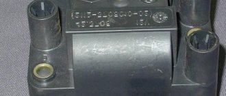
ignition module 2112-3705010-02 -2110.
2111-3707080 SLON High-voltage wire VAZ-2110 SLON kit (packed)…
Spark plugs for VAZ 2110 8 valves.
How to check the high-voltage wires of a car?
VAZ 2110 (VAZ 2110) – Replacement of I/O ignition wires.
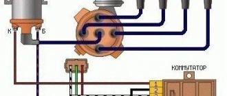
Diagram, procedure for connecting VAZ high-voltage wires.
The numbering of the wires is marked on white rings, and the qi numbers are cast on the module...
VAZ 2110 (VAZ 2110) – Replacement of I/O ignition wires.
Replacement of high-voltage wires and installation of the left rear view mirror, i.e...
Comment on Removing and disassembling the ignition sensor-distributor of the VAZ-2110.
High-voltage wire VAZ-2112 V16 silicone set, RF.
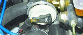
The car often does not start in wet weather. What could be the reasons?
Check the crankshaft sensor connector, most likely there is oxidation or a crack in the sensor. Accordingly, there will be no spark. The ignition coil is usually protected from splashes, except in basins, where it is quite possible that splashes will get on the coil connector. The coil itself and high-voltage wires do not suffer from moisture, unless you pour water into the wells.
1 Good answer
Thank you very much for your answer. Will watch
Spark plugs - high-voltage wires - ignition coils. Moreover, if the “problem level” has reached “won’t start”, and not just works uncertainly, then it’s the coils with a 99% probability
1 Good answer
Thanks for the answer! The car didn't start at all today. Will watch
How much gas does a car consume if it just sits running?
Conventionally, 1/2 of the engine volume per hour is considered. But this figure is from a warmed-up carburetor engine, near the injector, I think. it will be less. But it’s unlikely to be much less
4 Good answer
It was all about the candles)
1 Good answer
How to start an injection VAZ in severe frosts?
If the battery is good.
* Turn off all unnecessary consumers (heater, headlights, heated rear window, mirrors, radio)
* Turn on the ignition, wait 10-15 seconds for the fuel pump to create pressure in the rail
If it doesn’t start on the first try, wait a couple of minutes and repeat.
7 Good answer
What to do if the car fell into the water?
It was with such knowledge that people died. How about knocking it out with your elbow, well, if you have an iron elbow, then yes))) wait until the car is filled with water, Darwin Award)) it’s much easier to knock out the glass and immediately leave the car, oh yes, your elbow is not iron))) then take out the headrest and Here you have in your hands an excellent tool for breaking any atekl))
2 6 · Good answer
Why doesn't the car start the first time?
The car may not start the first time for the following reasons: 1) Weak battery charge (you can check either with special equipment, or try to turn on the light in the cabin and try to start the car - the lights in the cabin dim or go out when you try to start - low battery voltage). 2) Oxidation on the terminals - poor contact can affect the starting of the car, the problem can be easily solved - clean the terminals with sandpaper 3) Starter - if the battery and terminal are working properly, and when starting you hear clicks, metallic sounds - the problem is in the starter. 4) Power wires - damage to the power wires is possible; in this case, current does not flow to the spark plug. If there is damage, sparks are visible - the wires “break through”, replacement will help 5) Spark plugs - they may be flooded with fuel during unsuccessful starting attempts, or they may have carbon deposits on them that prevent the formation of a spark.
Source
Car ignition installation procedure
Construction machines and equipment, reference book
Category:
Car device
The ignition is installed to ensure normal operation and obtain the greatest power and efficiency of the engine. It is carried out if the ignition distributor is removed from the engine or if the ignition timing is not set correctly.
Installing the ignition on a GAZ-66 car in case of removing the ignition distributor is carried out in the following order: 1. Set the piston of the first cylinder to a position 4° before TDC on the compression stroke according to the marks on the flywheel and the arrow in the flywheel housing window. To determine the compression stroke, it is necessary to unscrew the first cylinder.2. Set the octane corrector to “O”, check the condition of the breaker contacts and the gap between them, and adjust if necessary.3. Insert the ignition distributor so that the vacuum regulator is directed upward, and by turning the drive shaft, insert the shank into the groove of the drive shaft.4. Using a screw, secure the fixed octane corrector plate to the drive housing and connect the wire to the distributor terminal.5. Loosen the nut securing the drive housing holder and turn the distributor housing to set the breaker contacts to the beginning of opening. It is better to determine the beginning of the opening of the contacts by the control light, for which connect it between the breaker terminal and ground (on cars with a contact-transistor ignition system, connect it between the unmarked terminal of the ignition coil and ground). Then turn on the ignition and, if the control lamp lights up, turn the distributor housing clockwise until the lamp goes out, and then slowly turn the distributor housing counterclockwise until the lamp lights up. In this case, the ignition distributor rotor must be located against the electrode with the number “1”.6. Tighten the nut securing the drive housing holder.7. Replace the distributor cap and connect the wire from the side electrode of the cap with the number “1” to the spark plug of the first cylinder. Connect the remaining wires to the spark plugs in the order of engine operation (1-5-4-2-6-3-7-8), following from electrode I clockwise.8. Connect the tube to the vacuum regulator.9. Check the correct installation of the ignition with the mileage of the loaded vehicle. To do this, on a flat road with a vehicle speed in direct gear of about 30 km/h, sharply press the throttle pedal all the way and hold it in this position until the vehicle speed reaches 60 km/h.
Rice. 1. Determination of TDC and setting the ignition on the ZIL-130 (ZIL-131) engine: 1 - crankshaft pulley; 2 — ignition installation indicator; I, II - ignition advance by 0° and 9°
If the ignition is installed correctly, during acceleration of the car, a slight detonation will be heard, which disappears when a speed of 40-50 jcm/h is reached. In case of strong detonation, it is necessary to move the index arrow of the upper plate of the octane corrector towards the “—” sign, and in the absence of light detonation, the index arrow must be moved towards the “+” sign. After adjusting the ignition timing, check the engine operation again using the vehicle's mileage.
The ignition installation on ZIL-131 and Ural-375D vehicles has features, the main ones of which are the following: 1. The piston of the first cylinder is installed in the compression stroke 9° before TDC with a contact ignition system and 6° before TDC with a transistor ignition system. Marks for setting the ignition are made on the engine crankshaft pulley (hole) and on the ignition setting scale.2. With a transistor ignition system, instead of installing contacts at the beginning of opening, it is necessary to rotate the distributor body to align the installation (red) marks on the rotor and stator of the pulse sensor and tighten the bolt securing the octane corrector plate to the distributor body.3. The spark plug wires are numbered, which makes it easier to distribute them among the cover sockets.4. On the Ural-375D vehicle, the ignition installation is not checked by mileage.
Read more: Main malfunctions of the ignition system and methods for detecting the causes of malfunctions
Category: – Car structure
What needs to be done before adjustment?
Adjustment is necessary for the “nine”, which has a carburetor installed. For those who have an injector, the good news is that the car has an automatic device that regulates the ignition itself. To make the adjustment you will need 2 devices: a strobe light and a speedometer. How to properly prepare everything for setup? Thus:
- Warm up the engine to normal operating temperature, which is approximately 85°C.
- The minimum engine idle speed must be set at 750-790 rpm. Turn the fuel mixture adjustment screw on the carburetor using a wrench to change the gauges. If the RPM meets the requirements, there is no need to change it.
Next you need to reach the marks on the flywheel. The algorithm of actions is as follows:
- Disconnect the silicone hose from the fitting on the carburetor vacuum regulator. It is worth checking for vacuum.
- Then turn off the engine.
- The silicone tube can be tied in a knot or closed.
- Take a 10mm wrench and remove 3 nuts on the distributor body.
- Let's inspect the crankcase. You need to find the marked hatch. This may take some time as it is often closed with a rubber stopper.
- Once you find the device, clean the scale inside it so you can see each mark clearly.
- Take a slotted screwdriver and turn the flywheel to the alignment mark. The stripe should be located opposite the triangle on the hatch scale (triangular notch). In this position, the ignition timing is 0 °, and the pistons of the 1st and 4th cylinders of the engine should be at the TDC point. This position is the starting point for further manipulations.
- Connect the strobe pins according to the instructions to the device. They are usually connected to the battery with correct polarity.
Return to contents
The principle of operation of a four-stroke power plant
You can understand why it is important to connect high-voltage wires correctly if you study the principle of operation of the power plant. The VAZ-2109 carburetor or injector operate on approximately the same principle, since both power plants are four-stroke
- First, the cylinder volume is filled with the fuel mixture and exhaust gases. This process is called "inlet".
- The engine then goes into compression. With it, the valves are closed, and the crankshaft and connecting rod move the piston upward. The mixture of fuel and air is transferred to the combustion chamber.
- During the expansion stage, the ignition is switched on and a spark appears. It ignites the fuel mixture, resulting in the formation of gases. They put pressure on the piston, causing it to move down. This force is transmitted through the connecting rod to the crankshaft.
- The process is completed by the “release” of exhaust gases through the exhaust system.
Rich mixture
The engine began to stall and stopped developing maximum power. When cold it may start and stall. In this case, the air-fuel mixture is to blame, where there is a lot of fuel and little oxygen.
It floods the spark plugs with gasoline and they refuse to work. From this you can judge the quality of the fuel mixture. If there is black soot, it is rich, if it is light, it is poor.
I wrote about this in detail in other articles, go to the channel, everything is written there, the link was above.
What to do
Look for the reason. There are several possible sources of problems:
- Mass air flow sensor
. It fails and the ECU receives incorrect readings for preparing the mixture. I wrote how to check it here. - The second lambda was covered with a “copper basin”
. There is also a separate article about it. - In the case of a carburetor, a high level in the float chamber
.
Finding the ignition moment in the ignition
On engine 402, ignition adjustment occurs according to the following algorithm and order:
- The crankshaft occupies a spatial position corresponding to 5 degrees of advance in ignition of the fuel mixture;
- This position can be easily achieved by aligning the mark on the pulley with the recess on the motor block;
- The coincidence means that the power plant has marked the end of a full piston stroke.
With the distribution sensor removed, adjustments are made as follows:
- I remove the spark plug from the head of the combustion chamber of the cylinder, which is listed as No. 1 in the order of fuel ignition;
- I cover it with a sheet of paper and turn the engine crankshaft;
- The air pushed out by the piston blows off the sheet, which indicates that it has reached the vertical maximum, from which the stroke begins;
- Then, using the keys, I set the octane corrector scale to 0.
Flooding when there is a spark and the starter is rotating
Experienced motorists are faced with situations when a spark appears, the starter rotates, but the lower part of the spark plugs is filled with gasoline. Do not be deluded by the presence of a fire, since this event can occur irregularly under pressure and can be lost while the engine is running.
The cause of the event appears to be excessive pressure in the cylinders. It will be possible to identify the event and the factors that motivate it by monitoring the car on a stand that simulates a combustion chamber.
We recommend paying attention to the valve timing, because their failure will be the cause of wet electrodes. In fuel-injected internal combustion engines, motorists should check the operation of the bypass valve located on the fuel rail
If its malfunctions are ruled out, you will need to find out the gasoline pressure in the rail, because the manufacturer regulates this parameter. Sharp fluctuations and going beyond the specified interval (larger/smaller sides) can block the start of the internal combustion engine or stimulate flooding of contacts for spark ignition.
Diagnostics will need to be carried out for the sensors of the electronic control system and for the injectors. An example of a failure is when the coolant temperature sensor sends incorrect data. In such a situation, the control unit unreasonably over-enriches the fuel mixture. Much less often, the culprit of incorrect impulses is a failed electronic control unit or a malfunction of its software. In this case, problems will appear not only with the ignition.
High voltage wires. Test
High voltage wires
Many car enthusiasts are interested in the question: “which high-voltage wires are better?” And few of them find the correct answer. In this article we will try to find out the answer to this question and find out the results of the high-voltage wire test.
One well-known auto magazine has already conducted a similar test, but this test is focused on carburetor cars. Do not forget that injection and carburetor engines have different requirements, for example, carburetor wires have a lot of radiation, which will interfere with the electrics of the injection engine. In this article we will test high-voltage ignition wires for injection engines, which are equipped in most of our cars.
Let us remember the Soviet-era GOST for high-voltage wires (GOST 14867-79). Here are the main points of the content of the standard:
Terms of Use:
- climatic version O according to GOST 15150-69;
- operating temperature from minus 60 to 110°C;
- The wire is resistant to oil, gasoline, ozone, mold, and does not propagate fire.
Let us immediately note that the conditions and situation in the world have changed greatly since 1979.
Reliability of wires according to the following criteria:
- Active resistance.
- Breakdown voltage (at least 40 kV according to GOST).
- Electromagnetic field level.
- Price.
The test involves complex and inaccessible equipment:
- multimeter MY68;
- universal breakdown installation UPU-1M;
- electromagnetic radiation level meter P3-31.
Our test involves high-voltage (HV) wires from the following companies:
- Slon.
- Ween.
- Cezar.
- Horse.
- Tesla.
- Finwhale.
Let's take a closer look at the candidates:
SLON
According to our information, SLON high-voltage wires have been installed from the factory on domestic cars for three years now. Sellers in auto parts stores also say the same. The resistance of wires 1 to 4 is: 4.24-4.74-5.19-7.60. They passed the breakdown test at 40 kV. The price for high-voltage SLON wires is approximately 480 rubles.
Ween
The country of origin is Belgium. They have resistance from cylinders 1 to 4: 6.17-6.57-7.52-9.89 kOhm. The breakdown occurred at around 35 kV. The price for Ween high-voltage wires is approximately 260 rubles.
Cezar
Country of origin - Russia. Resistance from cylinders 1 to 4 is: 3.10-3.53-4.23-5.34 kOhm. Passed a breakdown test at 40 kV. Estimated cost: 450 rubles.
Tesla
The country of origin is the Czech Republic. Tesla high-voltage wires have a resistance from cylinders 1 to 4 of 3.27-4.16-5.02-6.26 kOhm. Passed the breakdown test up to 50 kV. The cost of Tesla high-voltage wires is 450 rubles.
Horse
The country of origin is Russia. The resistance of the wires is 3.15-3.90-4.09-6.24 kOhm. The breakdown test passed up to 40 kV. The price for high-voltage Horse wires is approximately 360 rubles.
Finwhale
Country of origin: Germany. The resistance of wires of this brand is: 1.95-2.18-2.60-3.42 kOhm. The breakdown test has been passed (50 kV). The price for Finwhale high-voltage wires is 570 rubles.
Absolutely all the wires we examined are suitable for operation in Russian realities:
- all wires are silicone;
- soft;
- withstand temperature changes from -40 to +100 degrees Celsius;
- as for electromagnetic radiation, all wires are within the permissible limits;
Let's summarize a little and enter the data into the table. Based on the table, you can find out how much high-voltage wires cost and what characteristics they have.
Comparison table of high voltage wires
Do not forget that each engine is designed for certain wires, and not every wire will ensure its normal operation. Choose your GDP wisely!
Useful articles:
https://youtube.com/watch?v=K2nNmBjJOyo
The order of operation of all cylinders in the VAZ 2109 engine description, photo and video
Modern cars are mostly equipped with an internal combustion engine. In order to cope with various unforeseen situations on the road, you need to know the structure of the machine. The article describes the operating procedure of the VAZ 2109 cylinders, as well as possible malfunctions in the operation of the power unit.
Operating procedure
Often when repairing an engine, it becomes necessary to disconnect high-voltage wires. Some drivers, after disconnecting the wires, do not remember the order in which they were installed. As a result, there may be confusion with the wires, and if they are connected incorrectly, the car will not start. To avoid an unpleasant situation, you need to know how the internal combustion engine operates.
The principle of operation of the power unit is based on such a property of gases as the ability to expand when heated. A standard four-cylinder engine operates in 4 strokes:
- During the first stroke, the air-fuel mixture and part of the exhaust gases are “injected”. This mixture completely occupies the volume of the cylinder.
- In the second cycle, the “compression” process occurs. In this case, the valves are closed, and the piston moves upward due to the movement of the crankshaft and connecting rod. The working mixture fills the combustion chamber.
- On the third stroke, called “expansion,” a spark appears thanks to the spark plugs, which ignites the working mixture. The expanding gases exert pressure on the piston and force it to move downward. Then, thanks to the connecting rod, the crankshaft begins to move.
- On the fourth stroke, the process of “release” of exhaust gases is carried out. Through the exhaust valves they enter the exhaust system of the VAZ 2109.
In order for the operation of a multi-cylinder engine to be smooth and the crankshaft not to experience uneven loads, it is necessary that the work processes be carried out in a certain order.
There are different schemes that determine in what sequence the cylinders will function. The VAZ 2109 uses the following scheme: 1-3-4-2. The cylinders are numbered starting from the front cover of the power unit.
If we imagine the working process of the engine through the cylinders, then the order of operation is as follows:
- In the first cylinder, an upward movement occurs, the working process takes place: the air-fuel mixture burns, the gases expand.
- In the third, a “compression” process is carried out, in which the piston moves upward.
- The fourth receives the working mixture as the piston moves downwards, thus carrying out the “injection” process.
- In the second, the piston moves upward, while the exhaust gases exit through the exhaust valves.
Possible causes of failure
During the operation of the internal combustion engine, various malfunctions are possible. To detect them, you should perform the following sequence of actions:
- First you need to start the car. The engine should idle. At this time, you should listen to what sounds are coming from the exhaust pipe. If you hear regular popping noises, then one of the cylinders is faulty. The cause may be faulty spark plugs and lack of spark. The malfunction can also be caused by a large amount of incoming air or insufficient compression in the cylinder.
- It is necessary to inspect the candles. If there is carbon deposits, moisture or oxidation, you need to clean it. Check the gap between the electrodes, which should be 0.8 - 0.9 mm.
- Replace all spark plugs, regardless of their appearance and vehicle mileage.
- If there are irregular emissions, you need to inspect the high-voltage wires.
There should be no traces of oxidation on their tips, and the insulation should not be damaged. If defects are found, the wire should be replaced. Wires connecting to the coil - The gas distributor cap should be inspected. There should be no soot or cracks on it. The carbon contact should be checked for damage and wear.
- The rotor needs to be inspected. It must be solid and have no signs of burnout. All parts with defects must be replaced.
- The pressure in the cylinders is allowed to be no lower than 1.1 MPa, and the compression difference should not exceed 0.1 MPa. If the indicators do not correspond, engine repair is necessary.
Why the engine may unexpectedly “start up” after rain, and what to do about it
The long-awaited summer greeted residents of the central region with rain and deep puddles. It rained so much that, they say, even the country estate of Prime Minister Mishustin was flooded. And what the private property of ordinary citizens had to endure is scary to think about. It wasn't just real estate that suffered from the weather: transport suffered just as much.
Moisture is generally the most dangerous enemy of a motor, but the problem in 2020 is not so much water hammer - such a puddle has yet to be found in the city - but the percentage of air/water, which over the past week in the capital has reached the level of an aquarium. It is clear that in such conditions the processes of oxidation and decay proceed much faster. However, the blues of a power unit from heavy rains do not always lie in rust, and some symptoms, localized at an early level, even allow everything to be solved with “little loss.”
The first step is to disassemble the air filter housing and carefully diagnose the condition of the filter element: if the canvas is wet or even damp, then the problem has been found. A wet filter allows air to pass through much worse, therefore the engine runs on lean fuel, abuses fuel and generally fails. The logic of further actions is clear: the casing itself must be dried, vacuumed from dust, and the filter must be replaced or, at worst, dried. If after all the measures described above the internal combustion engine’s well-being has not improved, you will have to roll up your sleeves.
The plug on the oil filler neck will tell you about the condition of the oil: if a white “sour cream-like” coating has formed on it, then water has gotten into the oil and you should speed up the replacement. Alas, today's engines are not ready, like their predecessors, to drive with such lubrication. If no emulsion is found, then the devil is in the candles and high-voltage wires. Let's start with the last ones.
The wire running from the ignition coil to the spark plug should not crumble in your hands, be bent or damaged. It simply must look amazing and sparkle with novelty, because the speed and other characteristics of fuel ignition in the cylinder directly depend on it. You don’t need to be a rocket scientist to fully diagnose it. Any gap - chip, tear, scratch - indicates the need for replacement. The only equipment you need is your eyes.
If nothing like this is visually detected, wait until evening and ask a friend to start the car, first opening the hood and concentrating on the front side of the engine. Broken high-voltage wires will “generate” fireworks no worse than New Year’s
Source
Frequency of adjustment work
The frequency of adjustment directly depends on driving style, vehicle load, and the correct use of a particular brand of gasoline. If the car is operated without harsh driving and is not heavily loaded, then the adjustment period is 15 thousand km; if the vehicle is used for cargo transportation, then 10 thousand km. Well, if the wrong type of fuel is used for the cylinder head (cylinder head), regardless of the settings of the ignition system, the valve clearances are adjusted after 5-6 thousand kilometers.
The GAZ family of cars is equipped with the following internal combustion engine models: 402, 405 and 406 engines. The 402 engine is installed on both the Volga and GAZelle. Now it’s worth moving on to the indicators of acceptable standards.
How to set the ignition
In order to correctly adjust and set the ignition on a UAZ, you must follow the sequence of actions that are given in the user's repair manual.
Before you begin adjusting the ignition system, you must place the vehicle on an inspection pit or a special platform for repair work and apply the hand brake. The wheel mechanisms of the vehicle must be secured with a stopper or stop. The power unit must be turned off.
After this, you can begin installing the ignition. To do this, it is necessary to fix the piston of the first cylindrical element in the position of the highest dead center. In this case, you need to check that the hole on the crankshaft pulley coincides with the pin on the cover of the timing gear block. It is necessary to slightly lower the mounting bolt located on the plate to the distribution equipment sensor housing.
Then remove the cover from the distributor and rotate the crankshaft 180°. The octane corrector must be in the zero position. Then it is necessary to tighten the pointer to the housing of the distribution mechanism sensor with a bolt so that its position coincides with the octane corrector mark.
After this, we adjust the slider by rotating it counterclockwise. This will help eliminate gaps in the drive. When the tip on the stator coincides with the red mark, you can fix the plate with a bolt.
Then you need to replace the switchgear sensor cover and check that the ignition leads are installed correctly according to the operating order of the cylindrical mechanisms (1-2-4-3). You need to count in a counterclockwise direction. The ignition setup on the UAZ is completed.
Now it is recommended to start the power unit and warm it up to operating temperature (about +80°C). Then you need to sharply press the accelerator at a speed of 40 km/h on a straight section of the road.
In case of severe detonation, it is recommended to turn the distributor sensor 0.5-1 turn on the octane corrector scale in a counterclockwise direction.
If there is no detonation, you need to increase the advance angle by turning the sensor clockwise.
How to connect the ignition switch
Replacing the ignition switch involves dismantling the old one and installing a new mechanism with its subsequent connection. To remove the old lock you will need a Phillips and flathead screwdriver.
The procedure for dismantling the old vehicle ignition system lock:
- Remove the fasteners from the lower trim panel of the steering column.
- Insert the key into the lock and set it to the zero position, at which the steering mechanism will be locked.
- Remove the steering column.
- Unscrew the ignition switch mounting bolts.
- Insert a flat-head screwdriver into the small technological hole and press the latch that holds the lock.
- Push the lock out of its seat.
- Disconnect all system wires.
- Install a new lock, connect the wires and reassemble the mechanism, performing all the steps in reverse order.
All wires are connected in a clockwise direction.
To terminal number 50 you need to connect a red wire, which is responsible for the stable operation of the starter device.
To terminal number 15 you must connect a blue wire with a black stripe, which is responsible for heating the vehicle interior.
A pink wire is connected to pin number 30, and a brown wire is connected to 30/1.
The black wire must be connected to the INT connector, which is responsible for the operation of the side lights and headlights.
After all the wires are connected, you need to connect the battery terminal. A black wire should be connected to the top of the terminal. Then you need to start the engine and check the serviceability and functionality of the entire ignition system. First, it is recommended to check the operation of electrical devices, and then the serviceability of the starter mechanism.
If all wires are connected correctly, then when the ignition system key is in the zero position, all elements of electrical equipment will be disconnected from power. When the key is turned to the first position, the system is activated, which controls the internal combustion engine, generator set, headlights and brake lights, as well as washers and windshield wipers. When the key is moved to the second position, the starter is activated, the anti-theft system rod extends and retracts when the key position is changed.
If this does not happen, it means the wires are connected incorrectly. It is necessary to disassemble the mechanism and repeat the connection procedure.
The operating order of the VAZ 2106 cylinders: diagram, photo, video instructions
Much depends on the operation of the cylinders, so this unit must always be in working condition. Especially when it comes to old VAZ 2106 cars. In this article you can find out what is the operating order of the VAZ 2106 cylinders and for what reasons they may not work.
Work distribution
It may be necessary if it is necessary to identify a malfunction in the operation of the motor. Such breakdowns consist of unstable engine operation, that is, its tripping. It is necessary to diagnose the unit in cases where the engine power is too low, and the internal combustion engine itself regularly trips.
It should be added that the internal combustion engine throttles not only when driving at speed, but also in neutral gear. In addition to tripping and reduced power, fuel consumption in the vehicle increases. This sign is initial. In practice, interruptions in the operation of the power unit are observed when the carburetor is incorrectly adjusted, the spark plugs are broken, or one of the cylinders fails. In addition, air may leak into one of the cylinders.
But in order to accurately identify the malfunction, you need to know the operation of the cylinders in the vehicle. In a VAZ 2106 car it is as follows: 1-3-4-2. Accordingly, the numbers directly indicate the numbers of the cylinders themselves. The number “1” on the distributor cap is marked on the first cylinder. If you look at its cover from the side of the wires leading to the spark plugs, the cylinder operating mode will be 1-3-4-2.
Incandescent lamp instead of strobe light
Many car owners will ask a completely correct question - how to set the ignition of a VAZ 2109 in the absence of a strobe light. Of course, it is even more correct to work with a strobe, especially since in this case you can carry out the setup and adjustment work as accurately as possible. However, there is another method that will be useful for those who, for one reason or another, do not want to buy a strobe light.
To work, we need a regular incandescent lamp, designed for an operating voltage of 12 V. The entire algorithm of actions is as follows:
- Disconnect the wire going to the ignition coil from the distributor
- We connect one terminal of the incandescent lamp to the wire. Connect the second wire from the lamp to ground.”
- As in the case when the ignition of a VAZ 2109 is set using a strobe light, we loosen the nuts securing the distributor using a wrench.
- Turn on the ignition. The incandescent lamp should light up.
- Gradually turn the dispenser until the lamp stops burning. Next, turn the distributor slightly in the other direction. Once the lamp lights up again, you can tighten the mounting nuts.
Of course, the method described above cannot provide the highest possible control accuracy. However, with its help it is quite possible to achieve more or less correct and stable operation of the power unit.
Checking for correct installation
If the order is followed without errors in the ignition of the 402 engine, then the next task will be to check the power plant while the car is moving:
- We go out onto the highway and, when driving 60 km/h, turn on fourth gear. We are accelerating. The appearance of short-term detonation knocks indicates that the ignition is installed correctly.
- Prolonged detonation knocks are confirmation of incorrect setting of the advance angle.
In this case, you should reduce it with an octane corrector, moving it to one notch. If detonation cannot be heard at all, then the advanced ignition angle of the fuel mixture should be increased. And check again for correct installation by accelerating the car to 60 km/h and shifting to fourth gear.
Settings
The strobe is used like this:
After this, the actual adjustment begins.
The work is carried out in the following order:
The angle is adjusted by rotating to the right - this increases the angle, respectively, movement in the opposite direction decreases it.
It is not difficult to find out the exact direction - it is indicated by the scale marked on the distributor (there is an o and a “plus” there). Each division corresponds to 8 degrees. For this reason, adjustment is slow. After finding the desired position, the distributor is secured.
Operating procedure for an inline 4 cylinder engine
The operating order of a 4-cylinder engine is designated as X―X―X―X where X is the cylinder numbers. This designation shows the sequence of alternating cycle strokes in the cylinders.
The order of operation of the cylinders depends on the angles between the crankshaft cranks, on the design of the gas distribution mechanism, and the ignition system of the gasoline power unit. In a diesel engine, the fuel injection pump takes the place of the ignition system in this sequence.
Of course, you don’t need to know this to drive a car.
It is necessary to know the operating order of the cylinders when adjusting valve clearances, changing the timing belt or setting the ignition. And when replacing high voltage wires, the concept of the order of operating cycles will not be superfluous.
Duty cycle
Depending on the number of strokes that make up the operating cycle, internal combustion engines are divided into two-stroke and four-stroke. Two-stroke engines are not used in modern cars; they are used only on motorcycles and as starters for tractor power units. The cycle of a four-stroke gasoline internal combustion engine includes the following strokes:
- Intake - the exhaust valve is closed, the intake valve is open, the piston moves downward, and the air-fuel mixture is sucked in.
- Compression - all valves are closed and the piston moves upward, compressing the air-fuel mixture.
- Working stroke - the valves remain closed; at the end of the previous stroke, a spark ignites the compressed mixture. The piston, under the influence of gas pressure from the burnt mixture, goes down, rotating the crankshaft.
- Exhaust - at the end of the previous stroke, the exhaust valve opens. The piston, pushed by the crankshaft, moves upward and displaces combustion products into the exhaust manifold.
The diesel cycle is different in that during intake only air is sucked in. Fuel is injected under pressure after air compression, and ignition occurs from contact of the diesel engine with air heated by compression.
Numbering
The cylinder numbering of an in-line engine starts with the one furthest from the gearbox. In other words, from the timing belt or chain side.
Sequence of work
On the crankshaft of an in-line 4-cylinder internal combustion engine, the cranks of the first and last cylinder are located at an angle of 180° to each other. And at an angle of 90° to the cranks of the middle cylinders. Therefore, to ensure the optimal angle of application of driving forces to the cranks of such a crankshaft, the order of operation of the cylinders is 1-3-4-2, as in VAZ and Moskvich internal combustion engines, or 1-2-4-3, as in GAZ engines.
Alternation of measures 1-3-4-2
It is impossible to guess the order of operation of the engine cylinders by external signs. You should read about this in the manufacturer's manuals. The easiest way to find out the operating order of the engine cylinders is in the repair manual for your car.
crank mechanism
- The flywheel maintains the inertia of the crankshaft to move the pistons from the upper or lower extreme positions, as well as to rotate it more evenly.
- The crankshaft converts the linear movement of the pistons into rotation and transmits it through the clutch mechanism to the gearbox input shaft.
- The connecting rod transmits the force applied by the piston to the crankshaft.
- The piston pin creates a hinge connection between the connecting rod and the piston. Manufactured from alloyed high carbon steel with surface hardening. Essentially it is a thick-walled tube with a polished outer surface. There are two types: floating or fixed. The floaters move freely in the piston bosses and in the bushing pressed into the connecting rod head. The finger does not fall out of this design thanks to the locking rings installed in the grooves of the bosses. The fixed ones are held in the connecting rod head due to a shrink fit, and rotate freely in the bosses.
https://youtube.com/watch?v=ilZyCD-QlJg
Distributor design
The distributor circuit assumes the presence of such elements as:
- low voltage current breaker;
- high voltage current distributor;
- centrifugal ignition timing regulator;
- vacuum ignition timing regulator.
The distributor circuit is designed so that at a certain moment the breaker opens the primary ignition circuit, as a result of which a high voltage current is created in the secondary winding of the ignition coil. Through the distributor, this current is transmitted to the spark plugs in certain cylinders. The regulators automatically adjust the ignition timing, which depends on the current operating mode of the engine.
The distributor breaker is an electromechanical part and consists of the following parts:
- shaft;
- movable contact plate;
- movable contact plate;
- capacitor;
- frame.
The breaker shaft consists of two main parts. On one of them, depending on the type of breaker, cams are installed, the number equal to the number of cylinders in the engine. This distributor device is not very reliable, since a large number of contacts, as well as the presence of moving parts, lead to regular problems with this unit.
The distributor device, as well as its use in general, are outdated from the point of view of modern electrical equipment, but in our country there are still a lot of carburetor engines, so the problem of the performance of this unit is currently relevant.
As for where the distributor is located in the car, most often it can be found under the hood next to the engine, near the cylinder head or on it. Although the exact location of the node depends solely on the model of the machine.