Cars rolling off the assembly line of the Volzhsky Automobile Plant have long established themselves as reliable and trouble-free vehicles, whose distinguishing features are ease of operation and ease of maintenance. However, unfortunately, like any other mechanisms, they sometimes break down. According to reviews from owners, the central lock is considered a rather vulnerable element. It has several specific features, without knowing which it will not be possible to get rid of the problem without the help of a professional repairman.
Central locking diagram for VAZ 2114
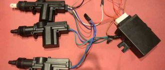
The system consists of the following components:
- mounting block;
- 8 amp fuse;
- 4 gearmotors (one in each door, and the one in the driver's door has a contact group);
- central locking control unit;
- wires (red, black, blue, yellow) and plugs;
- rods that are located in each door;
- limit switches that signal the current state of the door (open or closed).
Where is the central locking of the VAZ 2114
The central locking system is located in the driver's door, just like the electric drive. If we talk about the system as a whole, it is distributed over 4 doors (in some cases it also extends to the trunk), and the central panel (control unit).
Testing and diagnostics
conclusions
In this article, we touched upon only some of the most common problems associated with the operation, repair and maintenance of a centralized lock. Despite the fact that the node has plenty of problems, restoring its functionality is not a difficult, much less an impossible task. Usually, to achieve smooth, efficient operation of the system, only practical skills are missing. After receiving them, you will be able to repair any complexity! If you want to install the central locking on a VAZ 2114 yourself, then here is a video instruction:
Repair features
If the central locking of the VAZ 2114 has stopped working, then you need to conduct diagnostics and find the cause of the breakdown (the author of the video is Nikolay Bogdanov).
Then carry out the appropriate repairs. Problems with central locking on the VAZ 2114 most often arise at low temperatures and high humidity. The reason is the locks with solenoids that are installed from the factory. It is better to replace them with locks with an electric motor.
If the drive is not working on only one door, it is necessary to check its electrical circuit for an open circuit by testing it. Most often, broken wires are located in the corrugation. Since the doors are opened and closed frequently, the insulation cannot withstand the load. The break is restored by replacing the wire and connecting the broken sections using female-male terminals.
Central locking diagram for VAZ 2114
To connect a car alarm to the central locking on a VAZ 2114, you need to know the circuit diagram of the central locking system itself. This will allow you to understand what should be connected to what. Below is a standard lock diagram.
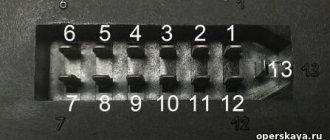
The control module is located under the vehicle's dashboard on the left side. There are six wires in its connector. If the white wire is connected to terminal 7, then it is responsible for unlocking the doors. But in some vehicles, terminals 5 and 7 may not be used. In this case, this function is performed by the brown wire connected to terminal 8. Terminals 5 and 6 are always responsible for locking. When planning to install the alarm, you need to make sure that the driver’s door contains exactly the 5-wire actuator, typical for this VAZ model. Some cars may have a toggle switch instead. In this case, you will need to install an actuator.
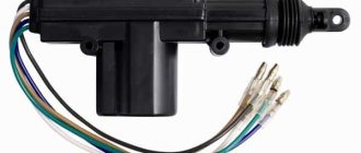
Central locking actuator
It is difficult to do this with your own hands without knowledge of auto electrics. Therefore, if they are absent, it is better to contact a car service.
Installation instructions for central locking
Before installing the central locking system, you should study the connection diagram
Photo gallery “Central locking diagrams”
The central locking control module is located on the left side under the panel. There are 6 wires coming from it. To install the central locking system, you need to disconnect the brown and blue wires.
Before connecting, you need to check that activators with 5 outputs are installed in the doors. If they are missing, they should be installed.
In a VAZ 2114 car, the wire responsible for opening the doors is usually white and connected to terminal 7. If there is no connection to terminals 7 - 5, then the 8th terminal is connected to the brown wire. This wire is responsible for opening the doors. Terminals 5 and 6 are for closing doors.
To install the central locking system, you must purchase additional items:
- 2-3 diodes 1N4001 at 1A;
- one diode 1N5401 3 A;
- 2 diodes of 4 or 5 A, if there are no separate outputs for turn signals.
After connecting the central locking system to the alarm, you need to check its functionality.
Alarm connection points for VAZ 2114
Most modern alarms can be connected to the door, hood and trunk switches.
Therefore, in order to connect the signaling system to the VAZ 2114, you need to observe the following points:
- Connector X3 with a blue-red wire to the car door sensors;
- X9 – to a two-level shock sensor, which is attached to a metal surface;
- X8 and X7 – usually not used;
- X6 – to the Valet service button, which is placed in a place hidden from prying eyes in the car;
- X5 – LED alarm indicator, which is located on the dashboard;
- X4 – to the transmitting sensor receiving module. It is installed on the windshield in one of the upper corners;
- X3 – connector with a large number of wires.
To connect the car alarm to all car systems, you need to connect the wires in this order:
- Red – to the “plus” of the ignition switch;
- Black/green and green/yellow – to direction indicators and sidelights;
- Black – for vehicle weight;
- Yellow – to the ignition switch;
- Gray – positive emergency siren;
- Blue/red – “plus” door entrance;
- Black/red – additional blocking relay;
- Orange/gray – to the hood opening sensor;
- Orange/white – trunk opening sensor;
- Orange/purple – to the brakes, according to the diagram presented in the instructions for the security device. It may differ for signaling devices from different companies;
- X2 – to door opening activators;
- X1 – to the ignition switch. It should be connected to the red wire.
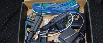
Used kit
The kit is small and is pictured in full below:
Used kit
The kit also includes instructions in English:
Instructions - description of the control unit
Connection diagrams
Theory
Before starting the installation, I want to warn you about the characteristics of my particular VAZ 2114 car (2006 model year, “Lux” equipment, the wiring under the dashboard is numbered as “VAZ 2115-...”), since I myself, from personal experience, have seen “four” and “tags” of the same year of manufacture, the same configuration, but with completely different wiring (I assume that this was due to different supplies of wiring to the conveyor).
After looking at the information on the Internet, I came to the conclusion that the overwhelming number of people install the control unit according to the wrong diagram “D”, from the instructions, which will not fit the Samar family (VAZ 2108/09/99/13/14/15) , since the opening and closing of doors (or rather, the supply of a signal to the BUDU (Door Lock Control Unit)) in Samara is controlled by a “minus”, and according to the “D” scheme, control occurs by supplying a “plus” to the BUDU. As I found out, this scheme only works when the standard BUDU is removed and the BU works every other time and only one button on the control key works. In my case, when connecting circuit “D” (I tried to connect it together with the BUBD), I burned several fuses and started looking for another connection method.
The scheme we need and works is scheme “C”
Scheme C
According to this scheme, our control unit will send a “minus” signal to the BUDU and everything will work normally, without removing the BUDU itself.
Installation
To begin with, I determined which wires in the control unit block I needed and which I did not. I didn’t need: - green wire - window closer; — blue wire — trunk opening; — pink wire — siren (there was a siren, but I just didn’t want to install it); Also, orange and orange-black wires are not needed, since according to scheme “C” they are not needed.
We still have: - red - “plus” 12v to the battery; — black — “minus” 12v (I connected the minus to the body, since the control unit does not necessarily require a minus power supply from the battery); — yellow and yellow-black — connect to the negative (I connected them to the main negative and all 3 wires to the body); - 2 brown ones - they supply a plus to the alarm button (some people connect them to the dimensions); — white — it sends a minus for closing; - white-black - it sends a minus to the opening.
For clarity
Used block with signatures
The control unit was installed on self-tapping screws, on the lower plastic part of the panel (to the left of the steering wheel height adjustment lever, next to the hood opening handle), but you can install it as you wish.
Plus, I stuffed it into the cambric and passed it through the rubber of the headlight range control, making a small hole with an awl (I couldn’t find a more convenient place, without drilling, in the whole car):
Positive wire
Under the hood I connected the plus directly to the standard terminal, tightening the bolt to “10”:
Positive terminal
I started connecting the emergency lights. I read on the Internet that you need to disassemble the hazard warning button, solder something, short circuit something, and in general it turns out that this round button interferes with normal steering and everywhere they show how to redo it. In general, I did not find a complete pinout of the button; with the help of a general electrical diagram and the scientific “poke method” I found out that:
— blue-black wire — left turn; - blue wire - right turn
Hazard warning button block
I again stuffed the two brown wires into the casing and brought them to the emergency flasher button block, pulled out the blue-black and blue wires from the block, using a small awl and “someone’s mother,” and soldered the brown wires directly to the “mother” terminals, so how I didn’t want to cut off the factory terminals (you don’t need a lot of tin, because if there is a lot of it, the terminals won’t fit back into the block):
Emergency signal block with soldered brown wires BU
Removing the BUDU turned out to be not an easy task; it is located above the hood release handle, almost under the dashboard, in general in not the most convenient place.
I have installed BUBD 21093-6512010-03 NPO Itelma.
BUBD 21093-6512010-03 NPO Itelma
This BUBD was installed on all Samara II (VAZ 2113/14/15), I’m not sure about the Samar I (VAZ 2108/09/99), check whether the BUBD is the same on your car, because the pinout may be different. The wires we need in the BUBD block are: - brown - closing the doors; — blue — opening doors By analogy with the emergency gang, I soldered the wires to the terminals according to the diagram: — brown from the BUBD with white from the control unit; — blue from BUBD with white and black from BU
BUBD block with soldered wires from the control unit
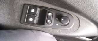
Now the most interesting part is the driver's door.
We remove the door trim, remove the black “anthers” from the inside.
There are several options:
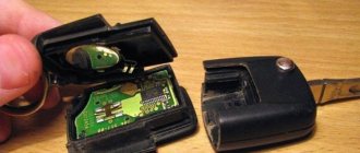
Option 1) You have a certain “microswitch” in the driver’s door, which, when you open the driver’s door with the key, sends a signal to the ECU and it opens the other doors (another name for such a switch is central locking, since without such a switch you would have to close each door separately). The driver's door motor is missing. There is also a block with two wires in the driver’s door: one is red, the other is yellow (the same blocks are 100% in the other 3 doors of the car) they supply power to the electric motor, which opens/closes the door lock.
Option 2) Everything is the same as in point 1, but the block with the red and yellow wires is missing (a very common situation, especially if the equipment is not “Lux”). In this case, you need to pull these wires from the ACU to the driver's door (the diagram of the door lock system will be below).
Option 3) You have/have had a non-standard alarm installed and now you have more wires in the driver's door than in the entire car. Here I can’t tell you anything, since I myself have not installed a non-standard alarm system in Samara, try to figure it out using a diagram of the door lock system.
Shown here is an unmodified VAZ 2114/15 (may be the same as the VAZ 2109/99):
Door lock system diagram
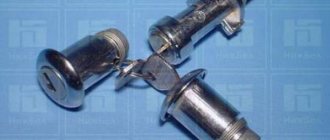
We have the first scenario, which means we must first remove the “microswitch”.
Microswitch
How to remove it is detailed here. Personally, I removed it with a Phillips “screwdriver attachment.”
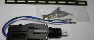
Next, we need to buy a so-called “actuator” (an electric motor (also known as a gearmotor, also known as a door activator) with a contact group, that is, it will perform not only the role of an electric motor, but also the role of a microswitch at once). I didn’t “reinvent the wheel” and install some strange actuators with strange alarms, which are not sold in all auto parts, for which you need to drill holes in the door, I just bought a standard actuator under the number: 21093-6512110-01, he already has All the wires and necessary connectors are present, there is no need to solder or drill anything:
Actuator 21093-6512110-01
You can also install a regular 2-pin electric motor, with two wires 21093-6512210-01, which is installed in the passenger doors:
Electric motor 21093-6512210-01
But in this case, you will only be able to open the doors with the BU key; only the driver's door can be opened through the driver's lock (3 passenger doors will not open), because it does not have a built-in microswitch, like in the 21093-6512110-01 actuator, which gives a return signal on the BUBD (in fact, because of the built-in microswitch it is called an actuator, this is its main difference from a conventional electric motor).
You also need to buy a rod for the driver's door lock, I couldn't find one for sale, so I bought several repair kits for the door lock rods and several bushings for the door rods, in the end I got an almost original rod (I copied the length and bend from the rod for the front passenger's door lock), even with ability to adjust the length of the pull:
Homemade door lock rod
You also need to buy long screws to fix the actuator in the door. This is roughly what it looks like when assembled:
Door with actuator
Well, everything works, but in this state the car will close all doors only with the BU key, the actuator will strongly resist, if you open the driver's door with a regular key, it will open the door, but will immediately close it, because the CU will give the command to close the doors . This way the door can be opened a couple of times without any problems, in case of emergency.
And here we could finish the article... But then I thought about it and decided that I want to keep both the functionality of the control unit and, just in case, keep the standard functionality of the central lock (so that all doors can be opened with a key).
Without soldering, I added the 3-pin block so that I could interrupt the constant negative (black wire):
Rework
Now in one position of the switch, only the control unit works, in another position of the switch, only the central lock works, while nothing is bridged and everything works. I placed the switch together with the window lift buttons into the “stuff pocket” of the door.
I placed and connected a light bulb, which, attention, blinks. This LED is connected to a separate small red connector on the control unit; it blinks when the control unit is in the “closed” state.
Bulb
Bottom line
In this simple way, we installed the Chinese central locking control unit without cutting a single factory wire or drilling a single extra hole in the body.
PS - in 3 months of operation nothing burned, melted or exploded. The control unit does not discharge the battery, since it is not an alarm and it does not have a constant connection with the key fob; the only source of consumption is the light bulb. The BU key is triggered when it is relatively close to the car; the CU's antenna is not large and picks up the signal in different places at a distance of 5 to 20 meters.
Price: - BU: 900 rubles - Actuator: 390 rubles - Door rod repair kit: 108 rubles (2 sets) - Door rod bushing: 40 rubles (2 pcs.)
Connecting to wires
- 2-3 pieces of 1N4001 diodes for a current of no more than one Ampere;
- One 1N5401 3 Ampere diode;
- Also, some security systems may require two 4-5 Ampere power diodes.
To connect the device to the central locking system, you need to find two wire harnesses on the floor next to the driver's door. To get them, you need to remove the sill trim and side panel. The first harness contains the door switch cable. A 1N5401 diode must be installed in its gap.
In the second harness you need to find the wire going to the handbrake, into which you should insert the second 1N4001 diode.
The blue cords of both harnesses must be connected to the car alarm.
Connecting autorun
If the alarm has an autostart function, it can be implemented on the “fourteenth”. The ignition switch of this car is equipped with three terminals:
- 15 – blue wire;
- 30 – lilac cable;
- 50 – red wire.
To connect the alarm you will need a 30 connector. The cable coming from terminal X1 should be connected to pin 15. The gray-black wire from connector X3 must be connected to the tachometer. This way the alarm will be able to read the revolutions. The black cable of terminal X1 is connected to ground. The red wire from the ignition switch needs to be broken. You should also cut the loop responsible for selecting the transmission, since the car is equipped with a manual transmission. After the work has been done, you should configure the autostart according to the instructions for the car alarm.
Video: Installing an alarm system on a VAZ 2114 from scratch (detailed guide)
Content
In order to protect your car from theft, you can equip it with a device such as a central electronic lock. To do this, it is not at all necessary to contact a service or specialized workshop, because in fact, its installation is much simpler than it seems at first glance. In today's article we will talk about how to install central locking on a VAZ 2114 and how to avoid possible mistakes.
Alarm system with central locking VAZ 2114
Does not work
The central locking motor may not work for a number of reasons: The winding has broken near one of the poles.
If the supply voltage is applied for more than one second, the collector will heat up and after the end of movement, the hot collector leads to the melting of the plastic under its plates. Because the brushes are spring-loaded, they begin to connect, squeezing out the molten plastic, and when the brushes connect, the central locking power fuse burns out (after which the activator rod stops moving even manually). Often the reason for this is cheap alarms (for example, there is not enough time for the central locking system to close completely) and the cold season. Overheating of the motor due to constant opening/closing in a short period of time (30-40 seconds).
Worn collector plates. In this case, the central locking does not always work, but every other time. The lubricant thickened, or the plastic was squeezed out from under the plates to the top due to the high pulse duration, and the collector overheated.
Lock connection diagram
In order to be able to install central locking on VAZ cars, the manufacturer equipped them with a special BUBD control module. You can find it directly under the torpedo, on its left side. If this module is missing, it will simply not be possible to install the device, so before you buy an electronic lock, you should first find out whether the module is installed on the car.
Control module
The connectors of this module are equipped with 6 wires of different colors as standard. If you are installing an alarm system on a VAZ 2114, you will need to turn off brown and blue in order to get the following connection diagram:
Before you begin installing the lock, you should make sure that five-wire actuators are installed in the car doors. If it turns out that ordinary switches are installed instead of them, then it will not be possible to connect the alarm.
Another important point to remember is the need to purchase additional electronic components that are not included in the alarm kit.
These include:
- diodes 1N4001 for 1 Ampere - 3 pieces;
- three-amp diode 1N5401;
- any diode rated for a current of up to 5 Amps (only if there are no separate outputs for turn signals).
Diode wiring
Once these components have been purchased, you can begin connecting the alarm. To do this, you should carefully study the drawing with the connection plan included in the instructions (this diagram of the VAZ 2114 central lock is duplicated below) and carry out the entire installation procedure in accordance with it. So, in the diagram, the index X2 indicates the six-pin control connector (BUBD), which was mentioned at the beginning. This is where you should start connecting, guided by the same “native” circuit.
After the lock is connected, all that remains is to insert into the wires in order to connect the alarm to the door sensors.
Connecting door limit switches VAZ 2114
It is done in the following order:
- Remove the sill trim along with the side panel by unscrewing their fastening screws.
- In the exposed wiring harness, find the cable going to the door limit switches (it has a white and black color) and solder a 1N5401 diode into its gap so that the direction of possible current flow is only towards the limit switches.
- In the second wiring harness, find two blue cables, from which you should make taps (using a wire of the same cross-section) and stretch them to the location where the alarm is attached.
- Cut the handbrake wire and solder a 1N4001 diode into its gap with the cathode towards the limit switch.
Tapping into wires
If necessary, you can make an insertion into the wires even before connecting the alarm to the connectors - this will not affect the functionality of the electronic equipment in any way.
The next step is to connect autorun. To do this, you will need to power the alarm to terminal 30 of the ignition switch, and connect the yellow cable coming from connector X1 to its 15th connector (according to the connection diagram).
After the alarm is connected to the on-board power supply, you will need to connect it to the speed sensor by connecting the gray-black wire coming from connector X3 to the tachometer. After this, all that remains is to connect the black wire X3 to the ground connector in the main unit.
At this point, the installation of the central lock can be considered complete.
Introduction
I went online to search for information on how people connect these Chinese units to a VAZ and came to the conclusion that everyone installs such units in a terribly artisanal way, removing half of the wiring, adding some of their own, and in the end, all this does not “successfully” work. Among the makeshift connection instructions, I came across the only normal article by Soliderus, who installed a similar control unit on his Chrysler; his article helped me a lot. But since we have a harsh domestic auto industry, we had to invent our own connection diagram, but first things first.
Please read this entire article first before disassembling the machine; you may not have any parts on hand or may be missing some of the original wiring.
Settings
After the alarm system on the VAZ 2114 is fully connected, its final configuration should be performed.
It is carried out as follows:
- Disable security.
- Set the ignition key in the lock to o.
- Press the button labeled Valet 6 times in a row.
- After the step marked “3”, immediately turn on the ignition (6 beeps should sound).
- Using the Valet button, select the required function (their list is given in the table below). To set it to the required value, press the corresponding key on the alarm key fob.
In this case, the most optimal (recommended) settings will be the following:
- for function 12 - value 3;
- for function 11 - value 4;
- for function 9 - value 3.
You can check whether the alarm is connected and configured correctly as follows:
- Disconnect the yellow cord coming out of block A91 from terminal 15 of the ignition switch.
- Turn the ignition key and start the engine.
- Pay attention to the alarm LED - if connected correctly, it should blink continuously.
The last thing I would like to talk about today is the importance of correctly connecting the tachometer, which directly affects the operation of the autostart.
To avoid errors, it is recommended to make this connection strictly in the following order:
- connect the red wire from the BUBD connector to the positive 12 volt terminal;
- connect the black wire of the 18-pin connector to the vehicle ground;
- Connect the gray-black wire of the same connector to the wire coming from the tachometer.
If you then turn on the ignition, then if the tachometer is connected correctly, the alarm indicator will begin to blink evenly.
What can happen to the lock - the seven most common breakdowns
Why did the central lock installed on the VAZ-2114 stop functioning normally? For the most part, failures occur in very wet weather or due to sudden temperature changes.
Signs of impending problems include:
- jamming;
- partial (or fuzzy) operation;
- Too loud clanging and noise from the gearbox.
First of all, failures occur due to the failure of the electromagnetic relay that controls the central locking power supply. It’s not difficult to make sure that it’s the culprit – it’s enough to install a known good one in its place.
An electrical short is also a common cause of central locking failure. Finding the problem here will be much more difficult. You will need to test the wiring in the circuit using a multimeter, starting with the battery. Before checking, do not forget to disconnect the negative terminal on the battery.
Damage to circuit integrity. In some places, the veins become unusable over time due to constant friction. In particular, the insulation may deteriorate or the wiring may break. There is a risk of loss of contact due to loosening of the connectors or their oxidation.
The design of the central lock has special springs, similar in shape to the letter “G”. Their purpose is to help when traction is triggered. However, over time, they stretch and, conversely, begin to impede the free movement of the above-mentioned element. The easiest solution is to simply remove all these springs. Their absence does not in any way affect the performance of the central locking system.
Failure of the central locking unit is very rare, however, the likelihood of such a breakdown should not be discounted. A regular tester will help you deal with the problem. In particular, you should measure the voltage directly at the contacts coming out of the block. It is not specific indicators that are of interest, but the very fact of the presence of nutrition. In the absence of a multimeter, the test is carried out differently:
- take a long enough wire;
- one end of it is connected to the battery negative;
- the second - to the BCZ;
- then an attempt is made to close/open the lock.
The absence of a result clearly indicates a node failure.
Also, due to certain overloads, the fuse often blows. This, in particular, is facilitated by the difficult movement of rods, etc. Often similar problems occur with cars that have undergone tuning in handicraft workshops, during which the door trims were replaced. Because of this, the gap under the casing is reduced, which prevents the walker from working normally. As a result, the servo requires more force to move the rods, which overloads the chain.
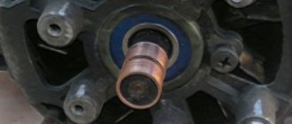
The central locking activator has failed. This element is one of the most vulnerable and capricious. Failure can be caused by:
- high humidity;
- wear;
- formation of an oxide film on the contacts.
Nuances of carrying out diagnostic measures
Those who have a car equipped with an anti-theft alarm should check it first. In this case, the performance of the central locking is tested:
- like using a remote control;
- and by unlocking with a key.
A failure of the alarm is indicated by the free opening and closing of doors manually.
Next, it is recommended to make sure that the battery is not discharged. Voltage is measured with a tester by applying probes to plus and minus. Normally, the reading will be 11.5 volts. With a low battery, the central locking system often malfunctions. If you don’t have a multimeter, it is recommended to take a regular 12 V light bulb.
In general, always start checking with the simplest steps. Only if these measures do not lead to anything, start disassembling the doors, and start with the driver’s side.
Useful video
You can glean additional useful information from the video below:
Published July 05, 2019
A useful addition to the design of any vehicle is a central lock, which simultaneously with opening the driver's door allows you to control all the doors of the car. Unfortunately, the VAZ-2114 central lock sometimes starts
does not function correctly, this is manifested in the lack of response when turning the key in the lock or when pressing the control key on the remote control. Let's consider the main reasons causing the malfunction of this unit.
Possible malfunctions of the locking system
If there is no reaction when you turn the key in the lock or press a key on the remote control, this means that the central locking is not working.
All causes of central locking malfunction can be divided into two types:
- technical;
- related to climatic phenomena.
In the first case, breakdowns are possible due to incorrect installation or configuration of the locking system. Subject to natural wear and tear after long-term use. The service life directly depends on the quality of the device.
In the second case, the central locking system may fail under the influence of low temperatures and it may freeze. The lock may not work if water gets into the mechanism during rain or melting snow.
The central locking system may not work due to an incorrectly installed or faulty alarm system. In this case, you should diagnose the locking system. The control activator is installed in the driver's door. As soon as the drive is activated, signals are sent through the appropriate channels to the remaining activators, according to which the required action is performed. Therefore, you should check the operation of the lock using the key and the button on the key fob.
If the doors sometimes close, sometimes they don’t, then the reason may be in the control circuit or a violation of the integrity of the electrical circuit of the car alarm. The reason why the central locking system fails to operate may be insufficient battery charge or a blown fuse. Depending on the circuit being used, there may be multiple fuses. They all need to be checked and faulty ones replaced.
The fuse can burn out as soon as it is installed, due to a short circuit or overload, for example, when controlling the central locking with a key fob, and not manually. In warm weather, the reason is a short circuit, which is possible due to poor contacts or an open circuit. The cause of the breakdown may be a malfunction of the central locking control unit.
You can check the operation of the unit using a multimeter by checking the power supply to the activators. Current is supplied to the contacts of the unit by unlocking and locking the driver's door. If the control unit is broken, it needs to be replaced.
How does the VAZ-2114 central lock function and where is it located?
This unit is aggregated with a lock on the driver's door through a control element (electric drive), which, in addition to allowing you to open or close it, additionally generates signals sent to the VAZ-2114 central locking unit, where, after their analysis and processing, commands are generated for actuators of the remaining doors of the car.
When closing, the control unit rod closes the corresponding pairs of contacts, as a result of which voltage is supplied to the other drive modules, which drives them. When opening and closing, different contact pairs are closed.
The figure shows a simple diagram of the VAZ-2114 central locking:
Common node faults
Often the central locking of the VAZ-2114 is controlled incorrectly due to the fact that the contact pairs are closed with a delay. A common reason for this is a violation of the adjustment of the thrust located between the gearmotor and the lock button, or its jamming. Simply put, when the button is pressed, the position of the rod does not allow the contact pairs of the drive to be completely closed.
The door on the driver's side may be locked, while the others will remain open due to the fact that the contacts of the control unit are not fully closed. This malfunction is purely mechanical in nature, and to eliminate it, it is enough to adjust the rod or the free play of the button in case it gets stuck.
In addition, such a problem can be caused by a malfunction of the VAZ-2114 central locking relay. In this case, you will have to replace the failed element.
In the case when the VAZ-2114 central locking completely stops responding to commands given by the driver, it is worth moving on to checking the electrical part of this unit. It is possible that this behavior of the system is caused by a blown fuse. Note that it can fail not only in the event of a short circuit, but also from constant overloads caused by the heavy movement of the core, or a violation of the adjustment of the rods.
Quite often, the reason why the VAZ-2114 central lock does not work is a violation of the integrity of the electrical wiring supplying power to it. The wires in the driver's door of a vehicle almost always break because it opens and closes more often than others. You can determine the damaged section of the wire using a multimeter. Less often than not, the control unit fails. In this case, the entire system either completely stops working or performs its functions incorrectly.
To prevent module malfunctions, it is necessary to pay attention to the condition of the activator, since its contacts can oxidize or burn, causing malfunctions. Periodic cleaning will significantly extend the life of the module.